
Recommended
Recommended
More Related Content
Similar to Analysis of T Beam and Prestressed Concrete Bridge Decks
Similar to Analysis of T Beam and Prestressed Concrete Bridge Decks (20)
More from ijtsrd
More from ijtsrd (20)
Recently uploaded
Recently uploaded (20)
Analysis of T Beam and Prestressed Concrete Bridge Decks
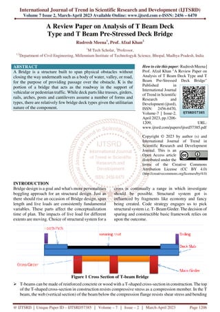
- 1. International Journal of Trend in Scientific Research and Development (IJTSRD) Volume 7 Issue 2, March-April 2023 Available Online: www.ijtsrd.com e-ISSN: 2456 – 6470 @ IJTSRD | Unique Paper ID – IJTSRD57385 | Volume – 7 | Issue – 2 | March-April 2023 Page 1206 A Review Paper on Analysis of T Beam Deck Type and T Beam Pre-Stressed Deck Bridge Rudresh Meena1 , Prof. Afzal Khan2 1 M Tech Scholar, 2 Professor, 1,2 Department of Civil Engineering, Millennium Institute of Technology& Science, Bhopal, Madhya Pradesh, India ABSTRACT A Bridge is a structure built to span physical obstacles without closing the way underneath such as a body of water, valley, or road, for the purpose of providing passage over the obstacle. K is the portion of a bridge that acts as the roadway in the support of vehicular or pedestrian traffic. While deck parts like trusses, girders, rails, arches, posts and cantilevers assume a number of forms and types, there are relatively few bridge deck types given the utilitarian nature of the component. How to cite this paper: Rudresh Meena | Prof. Afzal Khan "A Review Paper on Analysis of T Beam Deck Type and T Beam Pre-Stressed Deck Bridge" Published in International Journal of Trend in Scientific Research and Development (ijtsrd), ISSN: 2456-6470, Volume-7 | Issue-2, April 2023, pp.1206- 1209, URL: www.ijtsrd.com/papers/ijtsrd57385.pdf Copyright © 2023 by author (s) and International Journal of Trend in Scientific Research and Development Journal. This is an Open Access article distributed under the terms of the Creative Commons Attribution License (CC BY 4.0) (http://creativecommons.org/licenses/by/4.0) INTRODUCTION Bridge design is a goal and what's more personalities boggling approach for an structural design. Just as there should rise an occasion of Bridge design, span length and live loads are consistently fundamental variables. These parts affect the conceptualization time of plan. The impacts of live load for different extents are moving. Choice of structural system for a cross is continually a range in which investigate should be possible. Structural system got is influenced by fragments like economy and fancy being created. Code strategy engages us to pick structural system i.e. T- Beam Girder. The decision of sparing and constructible basic framework relies on upon the outcome. Figure 1 Cross Section of T-beam Bridge T-beams can be made of reinforced concrete or wood with a T-shaped cross-section in construction. The top of the T-shaped cross-section in construction resists compressive stress as a compression member. In the T beam, the web (vertical section) of the beam below the compression flange resists shear stress and bending IJTSRD57385
- 2. International Journal of Trend in Scientific Research and Development @ www.ijtsrd.com eISSN: 2456-6470 @ IJTSRD | Unique Paper ID – IJTSRD57385 | Volume – 7 | Issue – 2 | March-April 2023 Page 1207 POST TENSIONING DECK OR SPAN Pre throwing of components of a structure suggests that the solid is thrown in shapes at somearea other than the last position of the components. Figure 2 Pictorial view of a Pre-stressed Bridge Literature Survey General Ankur Gupta al. (2018) A Support span is a scaffold that usages support as the strategies for supporting the deck. A scaffold involves three segments: The Underpinning of projections and heading and Foundation of projection and dock and The Superstructure (support, section, or bend) and deck. A Support span is probable the most typically manufactured and utilized span in the world. Its central arrangement, in the most superior casing, can be appeared differently in relation to a log stretching out from one side to substitute over a stream or waterway. All scaffolds include two guideline parts: the base, and the superstructure. The Superstructure is everything from the bearing pads, up - it is what sponsorships the stores and is the most obvious piece of the extension. The Base is the foundation, what trades the stacks from the superstructure to the ground. The two segments should collaborate to make a strong, sturdy scaffold. Prestressed Concrete is generally concrete in which inside stress of sensible degree and scattering are introduced pressure coming about due to external burden are concentrated to needed degree. In this exploration work we are examining a support span with the impact of prestressed cement and contrast it and general deck span. Regarding limited basic examination, powers and cost investigation. Here it is reasoned that execution of prestressed deck is bringing about affordable, stable and burden opposing part. Yin Zhang. al. (2018) Twin-I girder bridge systems composite with precast concrete deck have advantages including construction simplification and improved concrete strength compared with traditional multi-I girder bridge systems with cast-in-place concrete deck. But the cracking is still a big issue at interior support for continuous span bridges using twin-I girders. To reduce cracks occurrence in the hogging regions subject to negative moments and to guarantee the durability of bridges, the most essential way is to reduce the tensile stress of concrete deck within the hogging regions. In this paper, the prestressed tendons are arranged to prestress the precast concrete deck before it is connected with the steel girders. In this way, the initial compressive stress induced by the prestressed tendons in the concrete deck within the hogging region is much higher than that in regular concrete deck without prestressed tendons. A finite element analysis is developed to study the long-term behaviour of prestressed concrete deck for a twin-I girder bridge. The results show that the prestressed tendons induce large compressive stresses in the concrete deck but the compressive stresses are reduced due to concrete creep. The final compressive stresses in the concrete deck are about half of the initial compressive stresses. Additionally, parametric study is conducted to find the effect to the long-term behaviour of concrete deck including girder depth, deck size, prestressing stress and additional imposed load. The results show that the prestressing compressive stress in precast concrete deck is transferred to steel girders due to concrete creep. The prestressed forces transfer between the concrete deck and steel girder cause the loss of compressive stresses in precast concrete deck. The prestressed tendons can introduce some compressive stress in the concrete deck to overcome the tensile stress induced by the
- 3. International Journal of Trend in Scientific Research and Development @ www.ijtsrd.com eISSN: 2456-6470 @ IJTSRD | Unique Paper ID – IJTSRD57385 | Volume – 7 | Issue – 2 | March-April 2023 Page 1208 live load but the force transfer due to concrete creep needs be considered. The concrete creep makes the compressive stress loss and the force redistribution in the hogging regions, which should be considered in the design the twin-I girder bridge composite with prestressed precast concrete deck. David Hester al. (2019) This article proposes a scaffold harm discovery technique utilizing direct turn estimations. At first, mathematical examinations are done on a one-layered (1D) essentially upheld pillar model stacked with a solitary moving point burden to explore the responsiveness of turn as a fundamental boundary for harm recognizable proof. Because of this review, the distinction in revolution estimations because of a solitary moving point load got for sound and harmed states is proposed as a harm marker. A generally basic research center examination is led on a 3-m long essentially upheld shaft design to approve the outcomes got from the mathematical investigation. The instance of multi-pivot vehicles is explored through mathematical examinations of a 1D extension model and a hypothetical reason for harm location is introduced. At last, a refined 3D unique limited component model of a 20-m long just upheld span structure is created by a free group of scientists and used to test the vigor of the proposed harm recognition philosophy in a progression of visually impaired tests. Praful N K al. (2019) The scaffold is a construction giving section over a deterrent without shutting the way underneath. The expected section might be for a street, a railroad, people on foot, a trench or a pipeline. T-pillar span decks are one of the chief kinds of cast set up substantial decks. T-bar span decks comprise of a substantial section necessary with braces. The limited component strategyis an overall technique for primary examination where the arrangement of an issue in continuum mechanics is approximated by the examination of a gathering of limited components which are interconnected at a limited number of nodal focuses and address the arrangement space of the issue. A straightforward range T-pillar span was examined by utilizing I.R.C. loadings as a one layered structure utilizing objective techniques. A similar T-pillar span is examined as a threedimensional construction utilizing limited component plate for the deck piece and shaft components for the primary bar utilizing programming STAAD ProV8i, three different range of 16m, 20m and 24m was investigated. Both FEM and 1D models where exposed to I.R.C. Loadings t (FEM) reproduction were directed to assess impact of the variety of pad profundity, coefficient of earth strain, width or point of scattering on the underlying way of behaving of the three layered box duct and to look at the exactness of FEM by contrasting the FEM results and IS Code strategies. It guides us in assessing box duct conduct under various pad profundities, the bx course need not be reproduced during enlarging of streets. Mangesh Saiwala (2020) Bridges are the structures which are built to associate the route isolated by stream or valley. In India, there are various codes which are utilized to design bridges. Each code have distinctive structural design provisions and methods. This examination incorporates two Indian Road Congress (IRC) codes which are utilized to design bridges those are IRC: 21-2000 and IRC:112-2011. IRC: 21- 2000 code of design rest upon the workingstress technique and limit state technique of design is utilized to frame IRC: 112-2011 code. In this study, three single span of T-beam girder bridge of 15m, 20m and 25m length are planned and designed according to both IRC codes and American Association Of State Highway Transportation Officials (AASHTO) code and STAAD PRO V8i Software is utilized to dissect the model. Two examinations are made. The primary examination is in between the design and analysis results by IRC: 21-2000 working stress technique with the results of AASHTO and another correlation is in between IRC 112-2011 limit state technique with the consequences of AASHTO and it will be inferred what examination have prettymuch similitude’s and furthermore the most ideal structural design technique or code for RCC T-beam bridge. Augustin 2021 This paper present review of literature regarding to comparative analyze and design a T-beam girder by using three rational methods (Courbon theory, Guyon-Massonet, Hendry-Jaegar). Theknowledge of Influence line and theories of structures are essential for the analysis and design of R.C.C T-beam bridge. IRC 21-2000 and IS 456- 2000 Code guidelines were preferred for the design purpose. The superstructure (RC slab, T-beam girder, Cross girder) Components have been designed using working state of design method under Class AA,70R (Tracked vehicle) Loading as prescribed by IRC were studied. bridge is a structure that provides passage over an obstacle without closing
- 4. International Journal of Trend in Scientific Research and Development @ www.ijtsrd.com eISSN: 2456-6470 @ IJTSRD | Unique Paper ID – IJTSRD57385 | Volume – 7 | Issue – 2 | March-April 2023 Page 1209 the path below. The required crossing may be for a road, rail, pedestrian, canal, or pipe. For constructing the bridges has many types of sections among which Tee beam and Box girder bridges have selected. T-beam bridges are castin- situ bridges, popular for short spans and economical. Similarly, the widely used box girder bridge selected which is economical for long spans, that may be either single or multi-celled girder. The type of bridge is concerned with providing maximum efficiency of material and construction technology. As the span increases, the dead load that is an important growth factor also increases. To reduce dead load, unnecessary material, which not used to its full potential, is removed from this section, which can be in the shape of box girders or cellular structures depending on whether the shear deformations neglected or not. In the present study, a two-lane simply supported RCC Tee beam girder and prestressed concrete box girder bridge analyzed and designed for dead load and IRC moving loads, where the considered moving load is of the tracked vehicle of class A-A loading. Courbon’s method adopted for analysis and designing. Dead load and live load calculations have done manually. Shear force and bending moment for a vehicular load have calculated. Piguead’s curves used for bending moment calculations. The main objective of this paper is to check whether both the T and box girder bridges have adopted for the assumed data with different span conditions of the girders is deviated within 5% from its theoretical position. The dynamicamplification factor of the bridge girder and slab are lower than the design value of that factor. The Weibull shape parameters are decreased, it which means that the bridge performance decreases under dynamic loads effect. OBJECTIVES To Study the effect of T beam Deck type and T beam Pre-stressed deck Bridge on performance of structure CONCLUSION T Beam Deck Prestress show better results in comparison to T Beam Deck, thus T Beam Deck Prestress slab can be considered for further research & design work. REFERENCES [1] Analysis and design of deck slab bridge. Iqra Zaffar and Priyanka Singh. Journal of Civil Engineering and Environmental Technology, Volume 3 [2] Analysis of T-beam Bridges International Journal of Scientific & Engineering Research 4(3):1-4. [3] Analysis of T-beam deck slab bridge in different methods, Tangudupalli Mahesh Kumar, J. Sudhamani . International Journal For Technological Research in Engineering, Volume 4. [4] Analysis of T-beam Bridges International Journal of Scientific & Engineering Research 4(3):1-4.and. prestressed concrete box girder bridges super structure under different span conditions based python programming for structural health monitoring of non-engineered RC frame box girders using pso method Asian Journal of Civil Engineering (Building and Housing) Vol. 11, No. 6 699-715. [5] Comaparative study of T-beam bridge longitudinal girder design using IRC112:201 and IRC21:2000R.Shreedhar,ShivanandTenagi, International journal of scientific & Engineering Research, Volume 6. [6] Comparative study of RCC slab bridge by working stress(IRC21-2000)and Limit state method(IRC112-2011) . (IJMETMR). [7] David N. Bilow, P.E., S.E. and Gene M. Randich, P.E., SLAB TRACK FOR THE NEXT 100 YEARS, Portland Cement Association, Skokie, IL. ISSN 1874:2334, Vol. 7, 2011. [8] Desai A K, Savaliya G. M, Vasanwala S.A: “static and dynamic analysis of cable-stay suspension hybrid bridge &validation, Vol. 6, Issue 11, 2015. [9] Dr. Husain M. Husain Mohanned I. Mohammed Hussein Professor / University ofTikrit M.Sc. / University of Baghdad, Finite Element Analysis of Post-Tensioned Concrete Box Girders, Volume 3 march 2011.