1. International Journal of Engineering Research and Development
e-ISSN: 2278-067X, p-ISSN: 2278-800X, www.ijerd.com
Volume 10, Issue 8 (August 2014), PP.19-27
Mechanical Behavior of Composite Tapered Lamina
Kiran Ravikumar1
1Manipal Institute of Technology, Manipal.
Abstract:- Composite lamina is widely used in a variety of applications. The laminas used are of different shapes.
Based on the shape of the laminas its mechanical behavior also changes. Laminas that are tapered along a single
direction are one of the most commonly used.We can analyze these laminas by considering them as a set of regular
laminas of varying lengths arranged one above the other. This paper gives an alternative set of formulae that can be
used to determine the mechanical behavior of such laminas. The formulae speak about the manner in which the
tapered lamina deforms along each axis. A Compliance matrix will be formulated specifically for the analysis of
composite tapered laminas. For this paper the data obtained from the derived formulae is verified against the data
obtained from already existing FEA software like ABAQUS.
Keywords:–Lamina/Ply; Strength; Mechanical Properties; Analytical Modeling; Composite; Stiffness Matrix;
Compliance Matrix.
Annotations –
푬풙 – Modulus of Elasticity in the fiber (x) direction
푬풚 – Modulus of Elasticity in the transverse (y) direction
푬풛 – Modulus of Elasticity in the out of plane (z) direction
풗풙풚 – Poison’s ratio relating the longitudinal strain in x direction to the transverse strain in y direction
풗풙풛– Poison’s ratio relating the longitudinal strain in x direction to the transverse strain in z direction
푮풙풚 – Shear modulus along the xy plane
I. INTRODUCTION
A unidirectional tapered Composite lamina is one in which the thickness of the lamina is varying linearly
from one end to the other. The fiber is laid along the direction of taper. This will develop an orthotropic property in
the lamina. When the lamina is loaded it will undergo deformations.
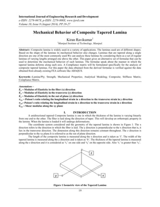
The coordinate system considered and the geometry of the tapered lamina is shown in Figure 1. The x
direction refers to the direction in which the fiber is laid. The y direction is perpendicular to the x direction that is, it
lies in the transverse direction. The dimension along this direction remains constant throughout. The z direction is
perpendicular to the xy plane.It is referred to as the out of plane direction.
The length of the composite lamina is measured along the x direction and is taken as ‘l’. The width of the
tapered lamina is measured along the y direction and is taken as ‘b’. The thickness of the tapered lamina is measured
along the z direction and it is considered as ‘t1’ on one side and ‘t2’ on the opposite side. Also ‘t1’ is greater than ‘t2’.
Figure 1 Isometric view of the Tapered Lamina
19
2. Mechanical Behavior of Composite Tapered Lamina
Figure 2 Side view of Tapered Lamina
Figure 3 Top View of the Tapered Lamina
A Lamina generally has two of its dimensions much greater than the third dimension. Hence a state of plane stress
can be considered.
20
THEORY
The composite can experience three different loading conditions under the plane stress condition. The
composite can be loaded along the xdirection or loaded along the y direction or the lamina can undergo a shear
loading on the xy plane. Each of these cases will be considered individually and the deformations developed will be
determined. The normal loads considered are to be tensile in nature. But the deformations under compressive
loading can also be determined as long as the lamina does not buckle.
The forces applied are such that the lamina will experience only elastic behavior.
A. Load along X direction
When the composite lamina is loaded along the X direction, three deformations result. The first one will be
along the loading direction itself called dx. The remaining two deformations are due to the poisson’s effect. The
loading condition is shown in Figure 4.
3. Mechanical Behavior of Composite Tapered Lamina
Figure 4 Load in the x direction
Figure 5 Considered Element
Figure 5 shows the element considered for analysis.
Fx is the load along the x direction, t is the thickness of a section at a distance x from the thicker end.
Consider the relation
푀표푑푢푙푢푠 표푓 푒푙푎푠푡푖푐푖푡푦 =
21
푆푡푟푒푠푠
푆푡푟푎푖푛
(1)
Stress =
퐹푥
푏 ∗푡
(2)
Strain =
푑 Δ푥
푑푥
(3)
Substituting in the Stress-Strain relation (1) and rearranging we get
푑Δ푥 =
퐹푥
퐸푥 ∗푏
∗
푑푥
푡
(4)
Where t = 푡1 − 푘 ∗ 푥
푡푘 =
1−푡2
푙
(5)
So,
푑Δ푥 =
퐹푥
퐸푥 ∗푏
∗
푑푥
푡1−푘 ∗푥
(6)
Integrating (6) with respect to x from 0 to l, we get the net deformation in x direction as
퐹푥 ∗푙
Δ푥 =
퐸푥 ∗푏∗(푡1−푡2)
∗ ln
푡1
푡2
(7)
For deformation in y due to the loading in x direction we have to consider the Poisson’s ratio,
푣푥푦 = −
푡푟푎푛푠푣푒푟푠푒 푠푡푟푎푖푛 (푦 )
푙표푛푔푖푡푢푑푖푛푎푙 푠푡푟푎푖푛 (푥)
(8)
푣푥푦 = −
푑 Δ푦
푑푦
푑 Δ푥
푑푥
(9)
Rearranging and substituting the value of 푑Δ푥
푑푥in (9),
푑 Δ푥
푑푥
=
퐹푥
퐸푥 ∗푏 ∗(푡1−푘 ∗푥)
(10)
푑 Δ푦
푑푦
=
−푣푥푦 ∗퐹푥
퐸푥 ∗푏∗푡
(11)
Integrating (11) with respect to y from 0 to b we get,
Δ푦 =
−푣푥푦 ∗퐹푥
퐸푥 ∗푡
(12)
The equation (12) shows that the deformation in the y direction is dependent on the cross section at which the
deformation is measured. When x = l, the deformation is maximum. Hence loading in the x direction introduces a
taper along the y direction as well.
4. Mechanical Behavior of Composite Tapered Lamina
For deformation in z due to the loading in x direction we have to consider the Poisson’s ratio,
푣푥푧 = −
22
푡푟푎푛푠푣푒푟푠푒 푠푡푟푎푖푛 (푧)
푙표푛푔푖푡푢푑푖푛푎푙 푠푡푟푎푖푛 (푥)
(13)
푣푥푧 = −
푑 Δ푧
푑푧
푑 Δ푥
푑푥
(14)
Rearranging and substituting the value of 푑Δ푥
푑푥at a section x in (14),
푑 Δ푥
푑푥
=
퐹푥
퐸푥 ∗푏 ∗(푡1−푘 ∗푥)
(15)
푑 Δ푧
푑푧
=
−푣푥푧 ∗퐹푥
퐸푥 ∗푏∗푡
(16)
Integrating (16) with respect to z we get,
Δ푧 =
−푣푥푧 ∗퐹푥
퐸푥 ∗푏
∗ ln
푡1
푡
(17)
The equation (17) shows that the deformation in the z direction is dependent on the cross section at which the
deformation is measured. When x = l, the deformation is minimum. Hence loading in the x direction increases the
taper along the z direction.
B. Load along y direction
When the composite lamina is loaded along the y direction, three deformations result. They are similar to the
previous loading condition. But here the deformations in x and z will result due to Poisson’s effect and the
deformation in y direction will be due to the load acting in the y direction. Figure 6 shows the loading condition
considered.
Figure 6 Load in the y direction
Now Fy is the load acting in the y direction. All other geometric parameters are the same.
퐹푠푡푟푒푠푠 =
푦
1
2
∗푙∗(푡1+푡2)
(18)
푠푡푟푎푖푛 =
Δ푦
푏
(19)
From the stress strain relation (1),
2∗퐹푦 ∗푏
Δ푦 =
퐸푦 ∗푙∗(푡1+푡2)
(20)
For deformation in x due to the loading in y direction from the Poisson’s ratio,
푣푦푥 = −
푡푟푎푛푠푣푒푟푠푒 푠푡푟푎푖푛 (푥)
푙표푛푔푖푡푢푑푖푛푎푙 푠푡푟푎푖푛 (푦 )
(21)
푣푦푥 = −
푑 Δ푥
푑푥
푑 Δ푦
푑푦
(22)
푑Δ푦
푑푦 =
Δy
b
This is because the total strain will be the same throughout for this loading condition.
Rearranging and substituting the value ofΔ푦/푏 in (22),
푑 Δ푥
=
푑푥
−2∗푣푦푥 ∗퐹푦
퐸푦 ∗푙∗(푡1+푡2)
(23)
Integrating (23) with respect to x from 0 to a section at a distance x from the thicker end,
Δ푥 =
−푣푦푥 ∗퐹푦 ∗2∗푥
퐸푦 ∗푙∗(푡1+푡2)
(24)
This shows that the deformation in x varies linearly with the taper.
For deformation in z due to the loading in y direction from the Poisson’s ratio,
5. Mechanical Behavior of Composite Tapered Lamina
23
푣푦푧 = −
푡푟푎푛푠푣푒푟푠푒 푠푡푟푎푖푛 (푧)
푙표푛푔푖푡푢푑푖푛푎푙 푠푡푟푎푖푛 (푦)
(25)
푣푦푧 = −
푑 Δ푧
푑푧
푑 Δ푦
푑푦
(26)
Again,
푑Δ푦
푑푦 =
Δy
b
Substituting and rearranging (26) we get,
푑 Δ푧
=
푑푧
−2∗푣푦푧 ∗퐹푦
퐸푦 ∗푙∗(푡1+푡2)
(27)
Integrating (27) with respect to dz from 0 to the thickness t at a section we get,
Δ푧 =
−푣푦푧 ∗2∗퐹푦 ∗푡
퐸푦 ∗푙∗(푡1+푡2)
(28)
The deformation in z direction depends on the thickness of the section at which the deformation is measured.
C. SHEAR DEFORMATION
When the composite lamina is loaded by shear it will undergo a deformation as shown in the Figure 8.
Figure 7 Shear Loading
Figure 8 Shear Deformation
6. Mechanical Behavior of Composite Tapered Lamina
The shear load is acting on the xy plane. Its magnitude is taken as Fxy.
푠푡푟푒푠푠 =
24
퐹푥푦
1
2
∗푙∗(푡1+푡2)
(29)
푠푡푟푎푖푛 =
Δ푙
푙
But,
Δ푙
푙
= Δ휃
From the stress strain relation (1),
2∗퐹Δ휃 =
푥푦
퐺푥푦 ∗푙∗(푡1+푡2)
(30)
The change in angle can be considered as the displacement of the face on which the shear load is acting.
II. VERIFICATION
The above derived formulae are verified against the deformations obtained from an FEA tool such as
ABAQUS. A 3 dimensional model of the tapered lamina is developed with the following dimensions.
l = 50mm
b = 50mm
t1 = 6mm
t2 = 3mm
The material considered is S-Glass epoxy composite with the following properties,
퐸푥 = 53e3 N/mm2
퐸푦 = 16e3 N/mm2
푣푥푦 = Vxz = Vyz = 0.26
푣푦푥 = 0.078
퐺푥푦 = 6.35e3 N/mm2
The respective deformations were found from the formula and from the software, for ten different load
values in each case. The error is calculated and it is plotted against the load values for each deformation.
All deformation values obtained are in mm.
A. LOAD IN X AXIS
The force acting in the x direction is considered to vary from 600 N to 6000N in steps of 600 N.The figures (Figure
9 to 11) shows the error obtained when compared with ABAQUS results for loading in X direction.
For deformation in x direction,
Figure 9 Error vs Load for deformation in x
For deformation in y direction,
7. Mechanical Behavior of Composite Tapered Lamina
Figure 10 Error vs Load for deformation in y
For deformation in z direction,
Figure 11 Error vs Load for deformation in z
25
B. LOAD IN Y AXIS
The force acting in the y direction is considered to vary from 450 N to 4500 N in steps of 450 N.The
figures (Figure 12 to 14) shows the error obtained when compared with ABAQUS results for loading in Y direction.
For deformation in y direction,
Figure 12 Error vs Load for deformation in y
For deformation in x axis
8. Mechanical Behavior of Composite Tapered Lamina
Figure 13 Error vs Load for deformation in x
For deformation in z axis,
Figure 14 Error vs Load for deformation in z
C. SHEAR LOAD
The shear force acting in the xy plane is considered to vary from 450 N to 4500 N in steps of 450 N.
The Figure 15 shows the variation of the error obtained when the results are compared with ABAQUS results.
Shear Deformations,
Figure 15 Error vs Load for shear deformation
26
9. Mechanical Behavior of Composite Tapered Lamina
III. COMPLIANCE MATRIX
The compliance matrix for a tapered composite lamina experiencing in plane stresses will be developed now.
Δ푥
Δ푦
Δ휃
27
=
푆11 푆12 푆13
푆21 푆22 푆23
푆31 푆32 푆33
∗
퐹푥
퐹푦
퐹푥푦
S11 =
푙
퐸푥 ∗푏 ∗(푡1−푡2)
∗ ln
푡1
푡2
푆12 =
−2 ∗ 푣푦푥 ∗ 푥
퐸푦 ∗ 푙 ∗ (푡1 + 푡2)
S13 = 0
푆21 =
−푣푥푦
퐸푥 ∗ (푡1 − 푘 ∗ 푥)
푆22 =
2 ∗ 푏
퐸푦 ∗ 푙 ∗ (푡1 + 푡2)
S23 = 0
S31 = 0
S32 = 0
푆33 =
2
퐺푥푦 ∗ 푙 ∗ (푡1 + 푡2)
To determine the deformation in the z direction,
Δ푧 =
−푣푥푧 ∗ 퐹푥 ∗ 푙 ∗ 푡
퐸푥 ∗ 푥 ∗ 푏 ∗ 푡1 − 푡2
∗ ln
푡1
푡
+
−푣푦푧 ∗ 2 ∗ 퐹푦 ∗ 푡
퐸푦 ∗ 푙 ∗ (푡1 + 푡2)
The Compliance Matrix will be as shown below,
푆11 푆12 0
푆21 푆22 0
0 0 푆33
IV. CONCLUSION
The formulae were derived for the composite tapered lamina. Using these formulae the deformations
experienced by the lamina was calculated for various load values. These results were compared with the results
obtained from the FEA tool ABAQUS and the two results were found to match with minimum error. The
compliance matrix obtained can be used to study the behavior of a tapered lamina under plane stress condition with
good accuracy.
ACKNOWLEDGEMENT
I would like to thank Dr. Satish Shenoy, Professor, Aeronautical and Automobile Department of Manipal
Institute of Technology for guiding and helping me in the completion of this Paper.
REFERENCES
[1]. Madhujit Mukhopadhyay, Mechanics of Composite Materials and Structures, Universities Press, 2004.
[2]. Isaac M. Daniel and OriIshai, Engineering Mechanics of Composite Materials, Oxford Universities Press,
1994.
[3]. K. He, S. V. Hoa and R. Ganesan, The study of Tapered Laminated Composite Structures, Composites
Science and Technology, 2000.