Study of Buckling Restrained Braces in Steel Frame Building

Conventional braces have limited deformation ductility capacity, and exhibit unsymmetrical hysteretic cycles, with marked strength deterioration when loaded in compression. To overcome the above mentioned problems, a new type of brace was developed in Japan called as buckling restrained braces, designated as BRB’s. These braces are designed such that buckling is inhibited to occur, exhibiting adequate behavior and symmetrical hysteretic curves under the action of both tensile and compressive cycles, produced by the action of seismic and wind forces. This paper presents experimental results concerning the lateral load carrying capacity of steel frame model by use of buckling restrained brace. This paper also includes the comparative study of lateral load carrying capacity of frame model for bare frame, frame with Conventional brace and frame with buckling restrained brace.

Recommended
Recommended
More Related Content
What's hot
What's hot (20)
Viewers also liked
Viewers also liked (20)
Similar to Study of Buckling Restrained Braces in Steel Frame Building
Similar to Study of Buckling Restrained Braces in Steel Frame Building (20)
Recently uploaded
Recently uploaded (20)
Study of Buckling Restrained Braces in Steel Frame Building
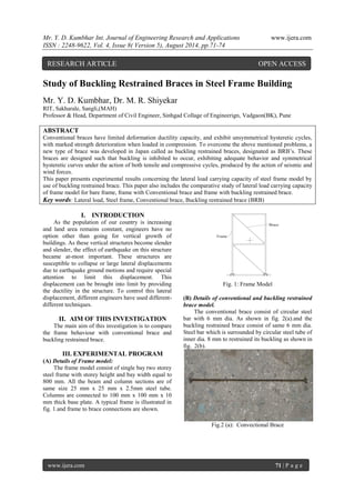
- 1. Mr. Y. D. Kumbhar Int. Journal of Engineering Research and Applications www.ijera.com ISSN : 2248-9622, Vol. 4, Issue 8( Version 5), August 2014, pp.71-74 www.ijera.com 71 | P a g e Study of Buckling Restrained Braces in Steel Frame Building Mr. Y. D. Kumbhar, Dr. M. R. Shiyekar RIT, Sakharale, Sangli,(MAH) Professor & Head, Department of Civil Engineer, Sinhgad Collage of Engineerign, Vadgaon(BK), Pune ABSTRACT Conventional braces have limited deformation ductility capacity, and exhibit unsymmetrical hysteretic cycles, with marked strength deterioration when loaded in compression. To overcome the above mentioned problems, a new type of brace was developed in Japan called as buckling restrained braces, designated as BRB’s. These braces are designed such that buckling is inhibited to occur, exhibiting adequate behavior and symmetrical hysteretic curves under the action of both tensile and compressive cycles, produced by the action of seismic and wind forces. This paper presents experimental results concerning the lateral load carrying capacity of steel frame model by use of buckling restrained brace. This paper also includes the comparative study of lateral load carrying capacity of frame model for bare frame, frame with Conventional brace and frame with buckling restrained brace. Key words: Lateral load, Steel frame, Conventional brace, Buckling restrained brace (BRB) I. INTRODUCTION As the population of our country is increasing and land area remains constant, engineers have no option other than going for vertical growth of buildings. As these vertical structures become slender and slender, the effect of earthquake on this structure became at-most important. These structures are susceptible to collapse or large lateral displacements due to earthquake ground motions and require special attention to limit this displacement. This displacement can be brought into limit by providing the ductility in the structure. To control this lateral displacement, different engineers have used different- different techniques. II. AIM OF THIS INVESTIGATION The main aim of this investigation is to compare the frame behaviour with conventional brace and buckling restrained brace. III. EXPERIMENTAL PROGRAM (A) Details of Frame model: The frame model consist of single bay two storey steel frame with storey height and bay width equal to 800 mm. All the beam and column sections are of same size 25 mm x 25 mm x 2.5mm steel tube. Columns are connected to 100 mm x 100 mm x 10 mm thick base plate. A typical frame is illustrated in fig. 1.and frame to brace connections are shown. Fig. 1: Frame Model (B) Details of conventional and buckling restrained brace model. The conventional brace consist of circular steel bar with 6 mm dia. As shown in fig. 2(a).and the buckling restrained brace consist of same 6 mm dia. Steel bar which is surrounded by circular steel tube of inner dia. 8 mm to restrained its buckling as shown in fig. 2(b). Fig.2 (a): Convectional Brace RESEARCH ARTICLE OPEN ACCESS
- 2. Mr. Y. D. Kumbhar Int. Journal of Engineering Research and Applications www.ijera.com ISSN : 2248-9622, Vol. 4, Issue 8( Version 5), August 2014, pp.71-74 www.ijera.com 72 | P a g e Fig.2 (b): Buckling Restrained Brace (C) Test Procedure and Instrumentation: Loading arrangement for frame is done manually by means of pulley and rope arrangements and loads are applied manually by means of sand bags as shown in fig. 3. Load applied to the top storey is half the load applied at bottom storey. Load is gradually increased from 2.5kg to maximum limit till the frame deflection is equal to allowable deflection as per the clause no.23.1.4. Of IS 800. The storey deflection is measured by the dial gauges attached at each storey. The results of the tested models were summarized in the table 1 to 3 and its graphical presentation is shown in figure 5 to 7. Fig. 3: Loading Arrangement Fig.4 Single bay Frame with Conventional brace Table 1 Un-Braced frame. Applied Load (Kg) Storey level Storey Deflection(mm) 2.5 top 2.19 5 bottom 0.45 5 top 3.78 10 bottom 1.03 7.5 top 5.86 15 bottom 1.87 10 top 9.64 20 bottom 2.27 Fig. 5 Load vs. Deflection for Un-Braced Frame Table 2 Conventionally Braced Frame. Applied Load (Kg) Storey level Storey Deflection(mm) 2.5 top 0.96 5 bottom 0.34 5 top 2.4 10 bottom 0.99 7.5 top 3.31 15 bottom 1.22 10 top 6.66 20 bottom 2.81
- 3. Mr. Y. D. Kumbhar Int. Journal of Engineering Research and Applications www.ijera.com ISSN : 2248-9622, Vol. 4, Issue 8( Version 5), August 2014, pp.71-74 www.ijera.com 73 | P a g e Fig. 6 Load vs. Deflection for Conventionally Braced Frame Table 3 Buckling Restrained Frame. Applied Load (Kg) Storey level Storey Deflection(mm) 2.5 top 0.35 5 bottom 0.19 5 top 1.66 10 bottom 0.48 7.5 top 3.31 15 bottom 1.87 10 top 5.23 20 bottom 1.43 12.5 Top 5.46 25 bottom 1.69 Fig.7 Load vs. Deflection for Buckling Restrained Brace Frame Fig. 8 & fig. 9 shows the comparative deflection of frame with three types of bracing arrangements for top and bottom storey respectively. Fig. 8 Comparison top storey deflection for single bay frame. Fig. 9 Comparison bottom storey deflection for single bay frame. Fig. 10 shows the graphical representation of storey deflection vs. storey level for three types of testing setup for single bay frame. Fig.10 Comparison storey deflection for single bay frame. IV. RESULT AND DISCUSSION Un-braces frame model: The Un-braced frame had the maximum deflection of 9.64 mm at top storey and 2.27 mm at bottom storey for load of 10kg and 20 kg 0 1 2 0 5 10 15 Storey Level Stirey Deflection(mm) UBF-1 CBF-1 BRBF-1
- 4. Mr. Y. D. Kumbhar Int. Journal of Engineering Research and Applications www.ijera.com ISSN : 2248-9622, Vol. 4, Issue 8( Version 5), August 2014, pp.71-74 www.ijera.com 74 | P a g e respectively. Conventionally Braced Frame The conventionally braced frame had the maximum deflection of 6.66 mm at top storey and 2.81 mm at bottom storey for load of 10kg and 20 kg respectively. Buckling Restrained Braced Frame The conventionally braced frame had the maximum deflection of 5.46 mm at top storey and 1.69 mm at bottom storey for load of 12.5 kg and 25 kg respectively. V. CONCLUSION The lateral load resisting capacity of steel frame with and conventional brace and with buckling restrained brace (BRB) has been studied. Study in the paper shows that by keeping the cross sectional area of brace equal to that of conventional brace and just putting it in the sleeve we can make it as buckling restrained brace. Following are the concluding remarks drawn from the study. Lateral deflection of frame for a specific horizontal load is much less in buckling restrained frame as compared to conventional braced frame, using the same cross section of a brace. The average ratio of lateral displacement of conventional braced frame to buckling restrained braced frame is 1.215. This shows BRB is more effective in resisting the lateral deflection. The average ratio of lateral load caring capacity of conventional braced frame to buckling restrained braced frame for a specified lateral deflection is 1.33. This shows the lateral load caring capacity of BRB is more than conventional brace. BRB also provides the cost effective solution in lateral load resisting system as compared to conventional brace. REFERENCES [1] Amiri J.V., Naeej M. and Monaeej M.R. (2013) “Seismic Retrofitting of Steel Frames with Buckling Restrained Braces”, Iranica Journal of Energy & Environment , Geo- hazards and Civil Engineering, ISSN 2079- 2115, pp. 178-185. [2] Deulkar1 W. N., Modhera C. D. & Patil H. S. (2010) ” Buckling Restrained Braces for vibration Control Of Building Structure” IJRRAS 4, pp-363-375. [3] Fahnestock L. A. Ricles J.M., and Sause R. (2007)” Experimental Evaluation of a Large-Scale Buckling-Restrained Braced Frame” Journal of Structural Engineering © ASCE, Pp-1205-1214. [4] Hussain Saif, Benschoten P. V., Satari M.A., Lin S. (2005) ” Buckling Restrained Braced Frame (BRBF) Structures: Analysis, Design and Approvals Issues” Coffman Engineers, Inc. Los Angeles, CA [5] Iwata Mamoru,(2004) “Applications-design Of Buckling Restrained Braces In Japan ” 13th World Conference on Earthquake Engineering Vancouver, B.C., pp-1-6. [6] Junxian Zhao, Bin Wu and Jinping Ou (2012)”Flexural Demand on Pin-Connected Buckling-Restrained Braces and Design Recommendations” journal of structural engineering © asce,pp-1398-1415 [7] Palazzo G., López-Almansa F., Cahís X. and F. Crisafulli X. (2008) ”Individual testing of dissipative buckling restrained braces” The 14th World Conference on Earthquake Engineering, Beijing, China,pp-21-29. [8] Qiang Xie, (2008)”Dual System Design Of Steel Frames Incorporating Buckling- restrained Braces” The 14th World Conference on Earthquake Engineering, 2008, Beijing, China, pp-12-17. [9] Rahai A.R., Alinia M. M., Salehi S. M. F.(2009) ”Cyclic Performance of Buckling Restrained Composite Braces Composed of Selected Materials” International Journal of Civil Engineerng. Vol. 7. [10] Shih-Ho Chao, Karki N. B., and Sahoo D.R. (2013)”Seismic Behavior of Steel Buildings with Hybrid Braced Frames” Journal of Structural Engineering © ASCE, pp- 1019- 1036