Download to read offline
![M.Vasavi et al. Int. Journal of Engineering Research and Application www.ijera.com
ISSN : 2248-9622, Vol. 7, Issue 3, ( Part -6) March 2017, pp.82-87
www.ijera.com DOI: 10.9790/9622-0703068287 84 | P a g e
2. It adds a new entry to the string table for S + b.
If the encoder finds the table full when it goes to
add an entry, it reinitializes the table before the
addition is made.
3. It resets S to contain only the byte b.
Where „S‟ is a sequence and „b‟ indicates the
number of bytes. Here „+‟ denotes appending b to
S.
V. PROPOSED WORK
This section deals with the proposed
techniques namely combined approach of (i) EZW
+ LZW. In this technique we make use of Huffman
encoder and also the LZW Algorithm for the
further compression. The results that which are
obtained are placed in the section[6]. EZW is one
of the wavelet based technique that which is
proposed for the image compression. In this we are
able to know about the “Discrete Wavelet
Transform” and also about the “Inverse Discrete
Wavelet Transform”. The DWT command in the
matlab performs a single-level one-dimensional
wavelet decomposition with respect to either a
particular wavelet ('wname', see wfilters for more
information) or particular wavelet decomposition
filters (Lo_D and Hi_D) that you specify.
Where Lo_D represents the low pass filter
decomposition Hi_D represents the high pass filter
decomposition Wname indicates the wavelet name
Wfilter indicates the wavelet filters that we are
using. The IDWT command in matlab performs a
single-level one-dimensional wavelet
reconstruction with respect to either a particular
wavelet ('wname', see wfilters for more
information) or particular wavelet reconstruction
filters (Lo_R and Hi_R) that you specify.
Where Lo_R represents the low pass filter re-
construction
Hi_R represents the high pass filter re-construction
Figure 2 shows the combined approach of
EZW algorithm, which uses a Wavelet Transform.
Here, EZW algorithm is applied on the input
image, and then if the output image is RGB in
nature, it is then given to the LZW algorithm for
the image compression and then we get the
processed image after EZW and LZW decoding.
Figure 2: EZW + LZW
For further encoding that means for the further
processing we process the ezw encoded signal to
the lzw encoder and then we are able to decode the
image with in a less time.
Fig 3: Image sub-bands after single-level image
decomposition for (a) scalar wavelets (b) multi
wavelets.
64 -34 49 10
14 -13
7 13 11 3
-5 0 7 9
10 -3 5 -7
4 -2 3 2
-31 23
15 14
-9 -7
3 -12
-14 8
-5 9 -1 2
-3 2
4 6 -2 3
5 -9 10 1
3 4 -8 2
9 -2 1 0
3 0
2 -3
5 11
6 4
-6 5
The above table shows the example for the compression technique. Here we need t apply some](https://image.slidesharecdn.com/p0703068287-170407111441/75/Image-Compression-using-Combined-Approach-of-EZW-and-LZW-3-2048.jpg)
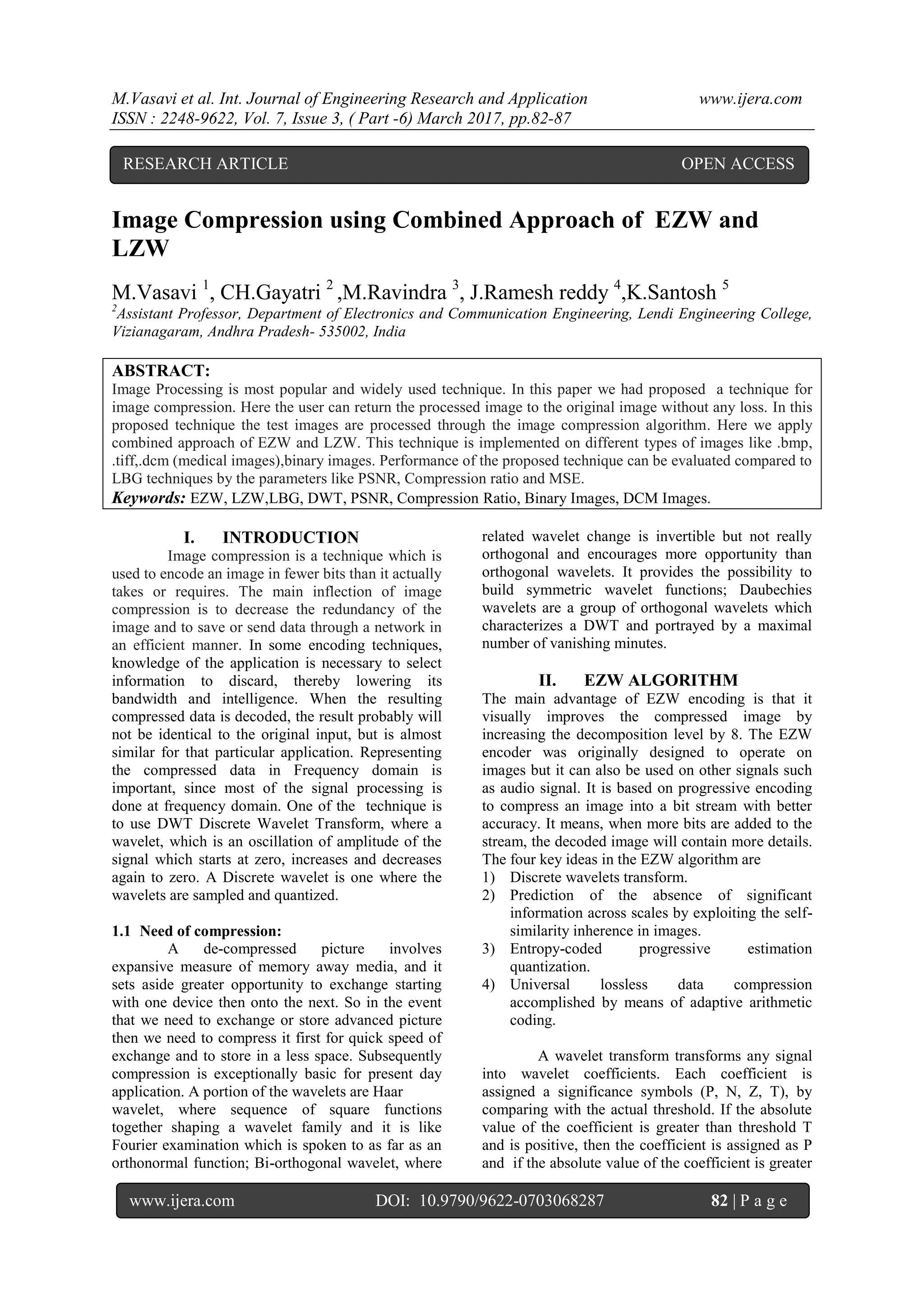
![M.Vasavi et al. Int. Journal of Engineering Research and Application www.ijera.com
ISSN : 2248-9622, Vol. 7, Issue 3, ( Part -6) March 2017, pp.82-87
www.ijera.com DOI: 10.9790/9622-0703068287 87 | P a g e
.
Fig: 7 Original .dcm image
Fig:8 Processed .dcm image
MSE 59.00
PSNR 41.33
Compression ratio 19.88
Table-4: The above results shows that the
proposed technique can compress the .dcm images
to high context and can also retrieve the original
image with small losses.
VII. CONCULSION
With this paper we came to conclude that
the proposed technique is able to compress the
image with in a short span of time compared to
other TREE Algorithms. We are able to have
compression ratio‟s for different images like for
gray scale images, we have obtain compression
ratio as 3% to 12% and for colour images including
maps 2% to 7.1% and for .dcm images 19.8% to
35.6%.
REFERENCE
[1]. Ms.Asmita A.Bardekar, Mr.
P.A.Tijare“Implementation of LBG
Algorithm for Image Compression”
International Journal of Computer Trends
and Technology- volume2Issue2- 2011.
[2]. Pallavi N. Save “An Improved Image
Compression Method using Vector
Quantization for Color Images”
[3]. International Journal of Computer
Applications (0975 – 8887) ,International
Conference on Computer Technology (ICCT
2015).
[4]. Aslam Khan Sanjay Mishra “ Image
Compression using Growing Self
Organizing Map Algorithm” IJCSNS
International Journal of Computer Science
and Network Security, VOL.14 No.11,
November 2014.
[5]. Ms. Asmita A.Bardekar#1, Mr. P.A.Tijare#2
“A Review on LBG Algorithm for Image
Compression” (IJCSIT) International
Journal of Computer Science and
Information Technologies, Vol. 2 (6) , 2011,
2584-2589.
[6]. R. Sivarajan, B. Elango, P.
Vedasundaravinayagam “Image
Compression using Combined Approach of
EZW and SPIHT with DCT” International
Journal of Science and Research (IJSR)
ISSN (Online): 2319-7064.
[7]. Janaki. R Dr.Tamilarasi.A “Visually
Improved Image Compression by using
Embedded Zero-tree Wavelet Coding” IJCSI
International Journal of Computer Science
Issues, Vol. 8, Issue 2, March 2011.
[8]. Embedded Zerotree Wavelet - An Image
Coding Algorithm Shufang Wu
http://www.sfu.ca/~vswu.
[9]. “EMBEDDED IMAGE CODING USING
ZEROBLOCKS OF
SUBBAND/WAVELET COEFFICIENTS
AND CONTEXT MODELING” Shih-Ta
Hsiang and John W. Woods Center for
Image Processing Research.
[10]. Akhilendra Yadav, M. A. Ansari, Manoj
Tripathy,” Improvement in Coding Time of
Embedded Zero Wavelet Tree” International
Journal of Computer Applications (0975 –
8887) Volume 49– No.3.
[11]. Rehna V. J and Jeya Kumar M.
“WAVELET BASED IMAGE CODING
SCHEMES: A RECENT SURVEY”.
International Journal on Soft Computing
(IJSC) Vol.3, No.3
[12]. Arber Borici, Saif Alzahir, “An Innovative
Lossless Compression Method for
Discrete-Color Images”, IEEE
TRANSACTIONS ON IMAGE PROCESSING.](https://image.slidesharecdn.com/p0703068287-170407111441/75/Image-Compression-using-Combined-Approach-of-EZW-and-LZW-6-2048.jpg)

This document presents a method for image compression using a combined approach of the EZW and LZW algorithms. The proposed technique effectively compresses various image types, including medical images, with the ability to recover the original image with minimal loss. Performance metrics like PSNR, compression ratio, and MSE are utilized to evaluate the effectiveness of the proposed method against existing techniques.