1. 1. http://www.solarbotics.net/starting/200111_dcmotor/200111_dcmotor2.html
In any electric motor, operation is based on simple electromagnetism. A current-
carrying conductor generates a magnetic field; when this is then placed in an
external magnetic field, it will experience a force proportional to the current in the
conductor, and to the strength of the external magnetic field. As you are well aware
of from playing with magnets as a kid, opposite (North and South) polarities
attract, while like polarities (North and North, South and South) repel. The internal
configuration of a DC motor is designed to harness the magnetic interaction
between a current-carrying conductor and an external magnetic field to generate
rotational motion.
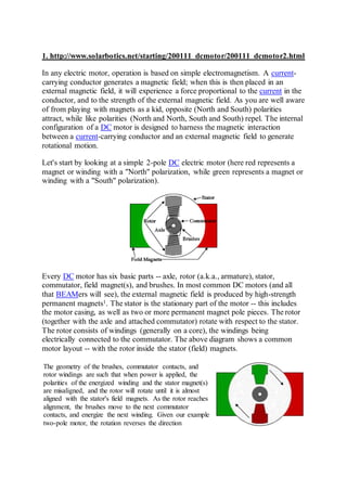
Let's start by looking at a simple 2-pole DC electric motor (here red represents a
magnet or winding with a "North" polarization, while green represents a magnet or
winding with a "South" polarization).
Every DC motor has six basic parts -- axle, rotor (a.k.a., armature), stator,
commutator, field magnet(s), and brushes. In most common DC motors (and all
that BEAMers will see), the external magnetic field is produced by high-strength
permanent magnets1. The stator is the stationary part of the motor -- this includes
the motor casing, as well as two or more permanent magnet pole pieces. The rotor
(together with the axle and attached commutator) rotate with respect to the stator.
The rotor consists of windings (generally on a core), the windings being
electrically connected to the commutator. The above diagram shows a common
motor layout -- with the rotor inside the stator (field) magnets.
The geometry of the brushes, commutator contacts, and
rotor windings are such that when power is applied, the
polarities of the energized winding and the stator magnet(s)
are misaligned, and the rotor will rotate until it is almost
aligned with the stator's field magnets. As the rotor reaches
alignment, the brushes move to the next commutator
contacts, and energize the next winding. Given our example
two-pole motor, the rotation reverses the direction
2. of current through the rotor winding, leading to a "flip" of
the rotor's magnetic field, driving it to continue rotating.
In real life, though, DC motors will always have more than
two poles (three is a very common number). In particular,
this avoids "dead spots" in the commutator. You can
imagine how with our example two-pole motor, if the rotor
is exactly at the middle of its rotation (perfectly aligned with
the field magnets), it will get "stuck" there. Meanwhile, with
a two-pole motor, there is a moment where the commutator
shorts out the power supply (i.e., both brushes touch both
commutator contacts simultaneously). This would be bad for
the power supply, waste energy, and damage motor
components as well. Yet another disadvantage of such a
simple motor is that it would exhibit a high amount
of torque "ripple" (the amount of torque it could produce is
cyclic with the position of the rotor).
So since most small DC motors are of a three-pole design, let's tinker with the
workings of one via an interactive animation (JavaScript required):
You'll notice a few things from this -- namely, one pole is fully energized at a time
(but two others are "partially" energized). As each brush transitions from one
commutator contact to the next, one coil's field will rapidly collapse, as the next
coil's field will rapidly charge up (this occurs within a few microsecond). We'll see
more about the effects of this later, but in the meantime you can see that this is a
direct result of the coil windings' series wiring:
3. There's probably no better way to see how an
average DC motor is put together, than by just opening one
up. Unfortunately this is tedious work, as well as requiring the
destruction of a perfectly good motor.
Luckily for you, I've gone ahead and done this in your stead.
The guts of a disassembled Mabuchi FF-030-PN motor
(the same model that Solarbotics sells) are available for you to
see here (on 10 lines / cm graph paper). This is a basic 3-
pole DC motor, with 2 brushes and three commutator
contacts.
The use of an iron core armature (as in the Mabuchi, above) is quite common, and
has a number of advantages2. First off, the iron core provides a strong, rigid
support for the windings -- a particularly important consideration for high-
torque motors. The core also conducts heat away from the rotor windings, allowing
the motor to be driven harder than might otherwise be the case. Iron core
construction is also relatively inexpensive compared with other construction types.
But iron core construction also has several disadvantages. The iron armature has a
relatively high inertia which limits motor acceleration. This construction also
results in high winding inductances which limit brush and commutator life.
In small motors, an alternative design is often used which features a 'coreless'
armature winding. This design depends upon the coil wire itself for structural
integrity. As a result, the armature is hollow, and the permanent magnet can be
mounted inside the rotor coil. Coreless DC motors have much lower
armature inductance than iron-core motors of comparable size, extending brush
and commutator life.
4. Diagram courtesy of MicroMo
The coreless design also allows manufacturers to build smaller motors; meanwhile,
due to the lack of iron in their rotors, coreless motors are somewhat prone to
overheating. As a result, this design is generally used just in small, low-power
motors. BEAMers will most often see coreless DC motors in the form of pager
motors.
Again, disassembling a coreless motor can be instructive --
in this case, my hapless victim was a cheap pager vibrator
motor. The guts of this disassembled motor are available
for you to see here (on 10 lines / cm graph paper). This is
(or more accurately, was) a 3-pole coreless DC motor.
I disembowel 'em so you don't have to...
……………………………………………………………
http://www.plantservices.com/articles/2010/02dcmotors/
Home / Articles / 2010 / DC motors: Why are they still used?
DC motors: Why are they still used?
The reasons come from the user base, R&D and
the application.
By Bob Simon M.Sc., P.E.
Feb 04, 2010
Print Email
i nShar e
- A A A A +
1 of 3 < 1 | 2 | 3 > View on one page
5. DC motors were first developed in the early 19th century and continue to be used
today. Ányos Jedlik is credited as being the first to experiment with DC motors in
1827. William Sturgeon (1832) and Thomas Davenport (1837) are credited with
taking Jedlik’s laboratory instrument and trying to commercialize it. It wasn’t until
1871 when Zénobe Gramme’s design of a dynamo was accidentally connected to a
second dynamo that was producing a voltage that the DC motor we think of today
start to turn and do work.
The DC motor reigned alone in the factory for only 11 years. In 1888, Nicola Tesla
stepped into the factory with today’s well known three-phase electric system and the
AC induction motor has been taking work away from the DC motor ever since.
So, the question remains — why has the DC motor continued to be used from 1888
until today? A primary reason is the motor’s variable speed characteristic. When the
voltage to a DC motor is increased from zero to some base voltage, the motor’s
speed increases from zero to a corresponding base speed. An induction motor, on
the other hand, always runs at full speed. If a speed other then this is desired, it must
be achieved via belts and pulleys, hydraulic pumps and motors, or gear boxes and
clutches. These devices provide for rotation at a speed something less (or greater)
then the design speed, but adds mechanical complexity.
A DC motor can develop full torque within the operational speed range from zero to
base speed (Figure 1). This allows the DC motor to be used on constant-torque
loads such as conveyor belts, elevators, cranes, ski lifts, extruders and mixers.
These applications can be stopped when fully loaded and will require full torque to
get them moving again.
Getting a variable DC voltage to a DC motor was done in several ways. The easiest
was with a large carbon rheostat that either increased or decreased the voltage
Figure 1. Torque comparison of DC and AC motors. Motor speed in per unit
values is located on the horizontal and torque developed by the motor in per
unit values on the vertical axis (1 = 100%). The green line is the nominal
developed DC motor torque and shows that a DC motor can develop 100%
torque from 0-100% speed. Neither the AC self-ventilated nor the forced
ventilated motors can match the torque development at very low rotational
speeds.
6. supplied to the motor. It also was done with motor-generator (MG) sets, which used
a constant-speed AC motor directly coupled to a DC generator. The generator’s field
was then increased or decreased. This resulted in an increase or decrease in the
generator’s terminal voltage. As terminal voltage increases or decreases, the speed
of the connected DC motor also increases or decreases.
Static inverters were developed later and the rectification of AC to DC was done
using vacuum tubes. Semiconductors were developed and the analog converter
replaced the rectifiers. Finally, the microprocessor was developed and the converter
went digital. That’s where the technology stands today with respect to providing an
AC-to-DC conversion.
As the development of semiconductors continued, the development of the digital DC
converter also continued. More importantly, this lead to the development of the AC
inverter. The AC inverter is the bit of engineering technology that was going to push
the DC motor down the same path as the Pickett slide rule and the Post draftsman’s
compass. The AC inverter allows a standard induction motor to be operated at any
speed, just like the DC motor. And, it does this without brushes. Brushes are the
primary maintenance headache when using a DC motor.
Performance characteristics
DC motors have three operating regions (Figure 1). The first is from zero to the base
speed and is called the called the constant-torque range. As motor voltage is
increased from zero to base voltage, the ability to develop full torque remains
constant. Motor power increases from zero to rated power as the voltage changes.
Often, this region is labeled VP/CT for variable power/constant torque. This
characteristic of a DC motor lent itself well to applications that had to operate at
various speeds while fully loaded.
http://www.plantservices.com/assets/Media/1002/Article_DCMotor2HR.jpg
7. The second region is called the field-weakening (FW) operational range or constant-
power range (Figure 2). This operating range normally ranges from the base speed
to a speed that is about two or three times the base speed. When at base speed (full
voltage) and the field current is reduced, the motor increases in speed. In this region,
the power remains constant as speed increases. The increase in speed comes at the
expense of a reduction in the torque available to turn the load. Often this region is
labeled CP/VT for constant power/variable torque.
The take up rolls at the end of a paper machine operate using this field-weakening
range. Paper comes off the machine at a fixed speed. When a new roll is started, the
load on the spindle is the lightest (no paper), but must rotate fastest because it is at
its smallest diameter. At this point, the DC motor is in its full field-weakened mode —
torque is at a minimum but speed is at its greatest. As the roll fills with paper, it
requires more torque to turn the spindle — the load is increasing. The paper comes
Figure 2. Power developed by a DC motor. In the B region the DC motor develops constant
torque and the power varies with speed. In the F1 region power remains constant and
torque varies. In the F2 region both power and torque varies.
8. off the machine at a fixed speed — as the paper roll builds, the roll diameter
increases, and the spindle needs to turn slower to keep the roll’s linear surface
speed the same as the paper machine. When operating in the field-weakening
range, the field is strengthened as the roll builds, which increases torque and
decreases spindle speed. In the paper industry, DC motors were used on more or
less all of the machines that did some type of work with paper rolls. It was the field-
weakening characteristic that allowed this to be the case.
The third operating range is an extension of the field-weakening range. This
extended field-weakening range ranges from about four to five times the base speed.
As the field is further weakened for even greater speed, it gets more difficult for the
current to move between the brush and the commutator. If too much current is
flowing, there’s an excess of sparking at the bush-commutator junction, which
damages both components. Damage can be prevented at these higher speeds by
limiting the current flowing to the brushes. This region is defined as a third area
because now both power and torque are dependent on speed. Often, this region is
labeled VP/VT for variable power/variable torque.
The application to which this third operating range is applied is a harbor crane that
unloads containers from a ship. As anyone that was in the Navy knows, ships are
built to be at sea. A cargo vessel tied to a pier isn’t making money. As the harbor
crane is picking up the container and lifting it out of the hold, the DC motor is
operating in the first region, which allows full torque from zero to base speed. Once
the container is placed on the pier and off the hook, the torque needed to lift and get
the hook back into the hold for the next lift is a fraction of the lifting torque. During
this time, the DC motor operates in the third region, cutting the cycle time between
lifts to a minimum. The quicker the hook returns to the hold, the more containers that
can be unloaded (or loaded) in a given time period and the quicker the ship gets
back to making money.
“For almost 100 years, the industry was using one electrical technology
to get a variable-speed shaft.”
– Bob Simon M.Sc., P.E.
Traditionally, DC motors have had a smaller power density then the conventional
induction motor. That is to say, for a given power, the physical size of the DC motor
is smaller then the physical size of an equivalent AC induction motor. Smaller is
better, and when thinking about footprint, traditionally DC has a smaller one. This
also is true for the DC converter as compared to an AC inverter. An AC inverter
normally needs two bridges — one to perform a rectification and another to do the
inversion to the needed frequency. The DC converter needs only a rectification
bridge and is, therefore, smaller in size, has less heat losses and is less complex.
A smaller motor will have a smaller rotor. A smaller rotor means less inertia. DC
motors are used in applications with an operating cycle that includes acceleration
and deceleration. With less rotor inertia, it takes less time and power to accelerate or
decelerate. This allows for quicker reversals, shorter cycle times and faster
production.
9. Because of the potential to have a high power density, DC motors can push well into
the 2,000 hp, 3,000 hp, 4,000 hp and greater ranges. Standard low-voltage induction
motor power ranges end around 800 hp, 1,000 hp or 1,200 hp. If an application
requires both more power and an AC induction motor, the voltage jumps into the
medium-voltage ranges of 2,300 V or 4,160 V and even in the high-voltage range of
11 kV. Having a facility with these voltages requires a different level of equipment
capabilities and a knowledge and skill level not found in the average trade
electrician.
Current state of the technology
Getting back to the original question: DC motors, why are they still used? There are
two reasons. The first can be summed up in two words: installed base. Let's
remember that the DC motor was the primary variable-speed shaft-turning device
since 1888. When AC inverters and AC motors started to replace DC in machines
can be debated, so let’s put a stake in the ground and call it 1987. For almost 100
years, the industry was using one electrical technology to get a variable-speed shaft.
It takes a good number of acres of ocean to get an aircraft carrier running at a full
bell turned around and headed in the other direction.
Engineers, machine builders and maintenance staffs had and have knowledge of
DC. DC converters are simpler in design than AC inverters, lower in cost and easier
to repair. DC motors can be repaired repeatedly. If a piece of machinery is powered
by a DC converter and motor, and if either one should fail, it’s easier (and cheaper)
to replace the failed item then to convert the machine to AC. If a plant has 10
machines using DC and wants to order an 11th, there’ll be a strong bias to purchase
what has worked before.
During past several years, DC motor manufacturers’ ongoing R&D has concentrated
on redesigning the most maintenance-intensive section of the DC motor, which is the
commutator and brushes.
As design engineers continue to increase the power density for a given frame size,
the motor’s commutator gets smaller. As the circumference of the commutator
shrinks, there’s less brush wear with every turn of the rotor. Reduced brush wear
results in extended intervals between brush changes. Engineers also have
redesigned brush blocks, pressure fingers and springs to allow for longer brushes.
With longer brushes, the interval between brush changes extends further, providing
for longer periods of operation without a maintenance shutdown. DC motors can be
purchased with brush wear sensors, which warn that a brush is worn down to its
lowest level and requires changing. Brush wear sensors often prevent commutator
damage from a worn brush being left in too long and resulting in costly repairs.
Active research and development
With the DC motor being one of the oldest technologies, you’d think R&D has ended.
Many motor companies continue to offer their older designs and there are some that
have dropped the product completely. But, there are motor companies that continue
to invest in developing the technology. Using software modeling tools, engineers can
get a better understanding of both the magnetic flux and thermal flows in the motor
10. laminations. Companies with active R&D programs are incorporating developments
in insulating materials into their designs. Slight changes in lamination geometries,
metallurgy, and insulating materials allow for increased power density and smaller
motors.
Companies with active R&D also are helping to reduce maintenance costs by
extending brush life. This can be done by designing smaller commutators,
lengthening the brushes, adding brush wear sensors and making it easier to replace
brushes. Studying the brush/commutator junction is a never ending activity. There
are groups using the latest sensor and control technology to determine what is the
best environment (temperature, humidity, pressures) that leads to optimum junction
performance. They’re also asking what can be done to ensure the junction
environment is optimum at the locations and ambient environments in which the
motor operates.
Everyone has heard the story that in 1899, the head of the U.S. Patent Office sent
his resignation to President McKinley because, he said, “Everything that could be
invented has been invented.” This turned out to be untrue and so is the tale that DC
motors are no longer being used and no one is investing in research and
development. The applications available for the DC motor are fewer than in the past.
However, the operational characteristics of higher power density, low inertia and
higher speed ranges continue to make the DC motor the preferred choice for many
machine builders. Also, the magnitudes of the installed and knowledge bases cause
users to request DC motors as prime movers even on new equipment
…………………………………………………………………