
Recommended
More Related Content
What's hot
What's hot (20)
Viewers also liked
Viewers also liked (20)
Similar to Guru Nanak Dev thermal plant bathinda industrial training by hardeep
Similar to Guru Nanak Dev thermal plant bathinda industrial training by hardeep (20)
Recently uploaded
Recently uploaded (20)
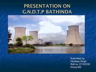
Guru Nanak Dev thermal plant bathinda industrial training by hardeep
- 2. INTRODUCTIONINTRODUCTION In India 65% of total power is generated by the Thermal Power Stations G.N.D.T.P foundation stone are laid on 19, November,1969 Guru Nanak Dev Thermal Plant (G.N.D.T.P) is a project of Punjab State Power Corporation Limited (PSPCL). It is situated at outside of city Bathinda, Punjab. Its total capacity is 440 MW as at present with two units working with capacity 220MW & two unit are repairing or designed under BHEL. Having four unit of 4 x 110 MW = 440 MW
- 3. It is a coal-based plantIt is a coal-based plant combustion of coalcombustion of coal Heat convert water in pipes into steam Heat convert water in pipes into steam Steam run the turbine Steam run the turbine Rotates generator three phase electricRotates generator three phase electric supply is producedsupply is produced INTRODUCTIONINTRODUCTION
- 4. Basic requirements of plantBasic requirements of plant WaterWater Fuel (coal)Fuel (coal) BoilerBoiler Steam turbineSteam turbine GeneratorGenerator Unit auxiliariesUnit auxiliaries
- 5. RANKINE CYCLERANKINE CYCLE Thermal power plantThermal power plant using steam as workingusing steam as working fluid basically works uponfluid basically works upon the principle of Rankinethe principle of Rankine cycle.cycle. Steam is generated fromSteam is generated from water in boilerwater in boiler Expanded in prime moverExpanded in prime mover or turbineor turbine Condensed in condenserCondensed in condenser and again fed into theand again fed into the boiler.boiler.
- 7. The general layout mainly consistsThe general layout mainly consists of three circuits:-of three circuits:- steam flow circuitsteam flow circuit Water flow circuitWater flow circuit Coal flow circuitCoal flow circuit
- 8. Steam flow circuitSteam flow circuit S.HEATER R.H. I.P L.PH.P condenser
- 9. Water flow circuitWater flow circuit ECONOMIZER B O I L E R C O N D E N S E R HOT WATER COOL WATER B.F.P STEAM COOLING D.M. PLANT
- 10. CHP (Coal Handling PlantCHP (Coal Handling Plant )) Coal is unloaded from wagonsCoal is unloaded from wagons using wagon tipplerusing wagon tippler When coal reaches the plant,When coal reaches the plant, normal sizenormal size of coal is about 500mmof coal is about 500mm primary crusher 120mmprimary crusher 120mm secondary crusher25mmsecondary crusher25mm coal mill pulverized coalcoal mill pulverized coal feeded in boiler.feeded in boiler. WAGON TIPPLER Coal Flow Circuit
- 12. Turbine used at G.N.D.T.P:Turbine used at G.N.D.T.P: S.noS.no Types of turbineTypes of turbine Turbine at G.N.D.P.TTurbine at G.N.D.P.T 1.1. Horizontal/VerticalHorizontal/Vertical HorizontalHorizontal 2.2. Single/Multi CylinderSingle/Multi Cylinder Multi CylinderMulti Cylinder 3.3. Condensing/nonCondensing/non CondensingCondensing CondensingCondensing 4.4. Reheat/non-ReheatReheat/non-Reheat ReheatReheat 5.5. Regenerative/ nonRegenerative/ non regenerativeregenerative RegenerativeRegenerative
- 13. ManufacturersManufacturers B.H.E.LB.H.E.L Rated speedRated speed 3000 r.p.m3000 r.p.m Number ofNumber of cylindercylinder ThreeThree Rated pressureRated pressure 130 kg/cm²130 kg/cm² RatedRated temperaturetemperature 535535°°CC CondenserCondenser vacuumvacuum 0.9 kg/cm²0.9 kg/cm² Main Technical Data:
- 14. Turbine AccessoriesTurbine Accessories Surface condenserSurface condenser Steam jet air ejectorSteam jet air ejector Low pressure heaterLow pressure heater High pressure heaterHigh pressure heater Chimney steam condenserChimney steam condenser Gland steam condenserGland steam condenser DeaeratorDeaerator Condensate extraction pumpCondensate extraction pump
- 15. CondenserCondenser 1.1. surface type condensersurface type condenser is usedis used 2.2. The coolant forThe coolant for condensing the steam iscondensing the steam is circulating water, which iscirculating water, which is inside the condenserinside the condenser brass tubes, and steam isbrass tubes, and steam is outside.outside.
- 16. Surface condensersSurface condensers No. of condenserNo. of condenser TwoTwo Cooling areaCooling area 3330 m23330 m2 No. of brass tubesNo. of brass tubes 60006000 Circulating water required for eachCirculating water required for each condensercondenser 15000T/Hr.15000T/Hr. Allowable difference between inlet &Allowable difference between inlet & outlet C.W. wateroutlet C.W. water 10°C Temp10°C Temp Vacuum in the condenserVacuum in the condenser 0.90 Kg/cm20.90 Kg/cm2 Technical data of condenser
- 17. Cooling TowerCooling Tower NumbersNumbers fourfour WaterWater cooledcooled 18000T/hr.18000T/hr. CoolingCooling rangerange 1010°°CC HeightHeight 120 to 122120 to 122 metersmeters These are massive Ferro-concrete structure having hyperbolic profile creating natural draught of air responsible for achieving the cooling effect.
- 18. LP and HP Heaters:LP and HP Heaters: The both are surface type i.e., condensateThe both are surface type i.e., condensate or feed water inside heater tubes in theor feed water inside heater tubes in the heater shell.heater shell. There are five LP heaters and two HPThere are five LP heaters and two HP heatersheaters
- 19. CHIMNEY STEAM AND GLAND STEAM CODENSER: There are additional two heating stagesThere are additional two heating stages provided in the regeneration system of theprovided in the regeneration system of the turbine for heating the condense flowingturbine for heating the condense flowing through it steam leaks off from the turbinethrough it steam leaks off from the turbine glands is used for heating the condensateglands is used for heating the condensate in these heaters.in these heaters.
- 20. DEAERATORDEAERATOR The function of the deaerator is to remove dissolved non- condensable gases and to heat boiler feed water.
- 21. METHOD OF INCRESING EFFICIENCY: 1. REHEATING: 2.REGENRATIVE FEED HEATING:
- 22. STEAM CIRCUIT AT G.N.D.P.TSTEAM CIRCUIT AT G.N.D.P.T