

Recommended
More Related Content
Similar to control lab Experiment No 3.pdf
Similar to control lab Experiment No 3.pdf (20)
More from Mahamad Jawhar
More from Mahamad Jawhar (20)
Recently uploaded
Recently uploaded (20)
control lab Experiment No 3.pdf
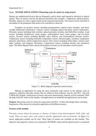
- 1. 1 Experiment No: 3 Name: SENSOR APPLICATIONS (Measuring cycle of a motor by using sensor) Sensors are sophisticated devices that are frequently used to detect and respond to electrical or optical signals. Most of sensors convert the physical parameter (for example: temperature, blood pressure, humidity, speed, etc.) into a signal which can be measured electrically. The sensors can be classified in accordance to the parameters that needs to be controlled or observed. Examples are position sensors including potentiometers, optical rotary encoders, and linear variable differential transformers. Velocity sensors including optical and direct current tachometers. Proximity sensors including limit switches, optical proximity switches, and Hall-effect switches. Load sensors including bonded-wire strain gauges, semiconductor force strain gauges, and low-force sensors. Pressure sensors including Bourdon tubes, bellows, and semiconductor pressure sensors. Temperature sensors including bimetallic temperature sensors, thermocouples, resistance temperature detectors, thermistors, and IC temperature sensors. Flow sensors including orifice plates, venturis, pitot tubes, turbines, and magnetic flowmeters. Liquid-level sensors including discrete and continuous types. The block diagram below detects the location of sensors in the automatic control system: Figure 3.1: Block diagram of general control system Making an application by using the most commonly used sensors in the industry such as capacitive, inductive and optic sensors that are reflective from reflector; may be with PLC. Aid with Y-0030-A03 module, connections of sensors and some characteristics features will be examined. With the help of the DC motor in the module, real applications are modelled and applications can be made. Purpose: Measuring cycle of a motor by using sensor and PLC. To have knowledge about switching frequencies of the sensors by trying this application with different sensors Features of the module; Proximity sensors detect the presence or absence of objects using electromagnetic fields, light, and sound. There are many types, each suited to specific applications and environments. In figure 3.2, sensor application module can be seen. Three types of sensors are available on this module. This inductive and capacitive sensors are connected to SENSOR1 socket and the optical sensor is connected
- 2. 2 to SENSOR2 socket. All inputs/outputs on the module can be connected to PLC via 2 mm sockets on "System Inputs" and "System Outputs" tables when required and they can be connected to PLC with I/O link cable via digital I/O Link connector. Figure 3.2 Sensor application module. There are plates that sensors on wings that are connected to DC can detect. At one side of the wing, there is a reflector that an optic sensor can detect. At the other side of the wing, there is an aluminium plate. Aluminium plate can be detected by inductive sensor. Capacitive sensor can detect both wings. Distance of sensors, which are connected to SENSOR1, to the wings can be adjusted by "sensor connection nuts". When the distance between motor wing and sensor is adjusted, this distance should not be smaller or bigger than the detecting distance of the sensor. Figure 3.3: Sensor sockets with electric connection and empty sensor sockets.
- 3. 3 Figure 3.4: Sensor module DC motor section. Motor Power Supply switch has two positions. When the switch is in Ext position, DC Motor ends are emptied so that they can allow external connections. When in INT position, motor speed can be changed with speed potentiometer. Technical specifications of inductive sensor: Figure 3.5A: Inductive sensor (connected to SENSOR1 socket). Figure 3.5B: Inductive sensor (schematic diagram and its work principles). Detecting distance: 0 … 8mm ( for mild steel) Switching Frequency: 1000 Hz Switching output: PNP N.O Operating Voltage: DC 10V... 30V Generator Output amplifier Metal Liminal construction with hysteresis of frequency Output signal
- 4. 4 Figure 3.6: Inductive sensor's detecting distance of various materials Inductive sensor detecting distance is found by multiplying it with value reduction factor for various materials. For example; detecting distance is 8 mm for steel and for brass it will be 8 mmx0,25=2mm. Technical specifications of capacitive sensor: Due to their ability to detect most types of materials, capacitive sensors must be kept away from non- target materials to avoid false triggering. For this reason, if the intended target contains a ferrous material, an inductive sensor is a more reliable option. Figure 3.7: Capacitive sensor (connected to SENSOR1 socket) Detecting Distance 0…12 mm (for the material with the lowest density) Switching Frequency 20 Hz Switching Output PNP N.O Operating Voltage DC 10V…30V
- 5. 5 Figure 3.8: Dielectric coefficients of various materials. Detecting distance of capacitive sensors show differences depending on the dielectric coefficient of materials. According to the table, the most detected material is water and the less detected material is teflon. Technical Features of Optic Sensor Reflective from Reflector: Figure 3.9: Optic sensor that is reflective from reflector (connected to SENSOR2 socket). Detecting Distance 80mm… 3.5m (with reflector) Switching Frequency 400 Hz Switching Output PNP. N.C Light switching Operating Voltage DC 10V…30V Optic sensor reflective from reflector is connected to SENSOR2 socket, when wing with reflector on the motor is aligned across the sensor, sensor will produce output. When there is an object between sensor and reflector or reflector is taken from in front of the sensor, sensor output signal is cut. Output signal of this sensor is connected to I0.1 in the module. Connection type of the application:
- 6. 6 Figure 3.10: Motor speed measurement with Inductive/Capacitive sensor