1. SECTION 2
AN OVERVIEW OF THE I
2.1 INTRODUCTION Several devices may be commanded to listen at once, but
only one device may be a talker at any given time* Otherwise,
The IEEE-488 bus is an instrumentation data bus standard- communications would be scrambled much like an individual
ized by the Institute of Electronic and Electrical Engineers in trying to pick out a single conversation in a large crowd.
1975= The most recent revision of bus standards was made in
1978; hence the complete description for current bus stan- Before a device can talk or listen, it must be appropriately ad-
dards is the IEEE-488-1978 designation. dressed. Devices are selected on the basis of their primary ad-
dress. To avoid confusion, the addressed device is sent a talk
This section gives a brief description of the general bus struc- or listen command derived from its primary address. Normal-
ture along with an outline of bus commands. The information ly, each device on the bus has a unique primary address so
presented here is not intended to be an in-depth description that each may be addressed individually. The primary address
of what is a very complex standard. More complete informa- of the Model 4853 interface Is set to 22 at the factory, but it
tion on the lEEE-488 bus, which is also frequently referred to may be changed to any value between 0 and 30 as described
as the GPIB (General Purpose Interface Bus), is available in Section 3.
from the IEEE and a variety of other sources.
Once the device is addressed to talk or listen, the appropriate
2.2 BUS DESCRIPTION bus transactions will take place. For example, if the Model
4853 is properly addressed to talk, it will normally place its
The IEEE bus was designed as a parallel data transfer medium data string on the bus one byte at a time. The controller will
to optimize data transfer without using an excessive number then read this information, and the appropriate software can
of bus lines. In keeping with this goal, the bus has only eight then be used to channel the information to the desired loca-
data lines that are used for both data and some commands. tion. Other bus functions and instrumentation may be con-
Five bus management lines and three handshake lines round trolled by special bus commands as described in paragraph
out the complement of signal lines. Since the bus is of parallel 2.3.
design, all devices connected to the bus have the same infor-
mation available simultaneously. Exactly what is done with 23 lEEE-488 BUS LINES
the information by each device depends on many factors, in-
cluding device capabilties. The signal lines on the lEEE-488 bus are grouped into three
general categories. The data lines handle bus information,
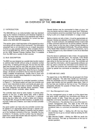
A typical bus configuration for controlled operation is shown while the handshake and bus management lines ensure that
in Figure 2-1. The typical system will have one controller and proper data transfer and bus operation takes place. Each of
one or more instruments to which commands are given and, the bus lines are inverted so that low is true. The following
in most cases, from which data is received. Generally, there paragraphs describe the purpose of these lines, which are
are three categories that describe device operation. These shown in Figure 2-1.
designations include: controller; talker; listener.
2.3.1 Bus Management Lines
The controller does what its name implies: it controls other
devices on the bus. A talker sends data, while a listener The bus management group is made up of five signal lines
receives data. Depending on the instrument, a particular that send certain single-line bus commands and ensure an
device may be a talker only, or both a talker and a listener. orderly transfer of data. These lines are used to send the
The Model 485, through the 4853 interface, is capable of be- single-Sine commands described in paragraph 2.4.
ing both a talker and a listener, but it does not have controller 1. ATN (Attention)—The attention line is one of the more im-
capability. portant management lines. The state of the ATN line
determines whether information on the data bus is to be
Any given system can have only one controller (control may considered data or a command as described in paragraph
be passed to an appropriate device through a special com- 2.4.
mand), but any number of talkers or listeners may be present 2. IFC (Interface Clear! — Setting the »FC line true flow)
up to the hardware contraints of the bus. Generally, the bus causes the bus to go to a known state by sending the IFC
is limited to 15 devices, but this number may be reduced if command.
higher than normal data transfer rates are required or if longer
than normal cables are used. 3. REN (Remote Enable) —Setting the REN line sends the
REN command. This sets up instruments on the bus for
remote operation.
2. 4. EOI (End or Identify)—The EOI Sine is used to terminate a transfer regardless of the transfer rate. Generally, data
mults-byte transfer sequence. transfer will occur at a rate determined by the slowest active
5. SRQ (Service Request)—The SRQ line is set low by a bus device on the bus.
device when it requires service from the controller.
One of the handshake lines is controlled by the data source,
TO OTHER DEVICES while the remaining two lines are controlled by accepting
devices. The three bus handshake lines are:
1. DAV (Data Valid)—The source controls the state of the
DEVICE 1
I t l t t fff DAV line.
2. NRFD (Not Ready For Data)—The acceptor controls the
ABLE TO state of the NRFD line*
TALK, LISTEN.
AND CONTROL 3. NDAC (Not Data Accepted)—The acceptor also controls
{COMPUTER? the NDAC line.
DATA BUS
The complete handshake sequence for one data byte is
shown in Figure 2-2. Once data is high, indicating that all
devices on the bus are ready for data. At the same time
DEVICE 2 NDAC should be low from the previous byte transfer. If these
ABLE TO
conditions are not met, the source must then wait until NRFD
TALK AND
LISTEN
and NDAC lines have the correct status* Because of the
possibility of a bus hang up, some controllers have time-out
DATA BYTE
TRANSFER routines to display error messages if the handshake sequence
CONTROL stops for any reason.
Once the NRFD and NDAC lines are properly set, the source
sets the DAV line low, indicating that data on the bus is now
DEVICE 3
ONLY ABLE N- valid. The NRFD line then goes low; the NDAC line then goes
TO LISTEN high once all devices on the bus have accepted the data.
(PRINTER)
GENERAL Each device will release the NDAC line at its own rate, but the
INTERFACE NDAC line will not go high until the slowest device has ac-
MANAGEMENT cepted the data.
Once the NRFD and NDAC lines are properly set, the source
DEVICE 4 sets the DAV line low, indicating that data on the bus is now
ONLY ABLE
TO TALK
valid. The NRFD line then goes low; the NDAC line then goes
high once all devices on the bus have accepted the data.
D I G I T S DATA Each device will release the NDAC line at its own rate, but the
18 LINES) NDAC line will not go high until the slowest device has ac-
cepted the data.
^ HANDSHAKE
After the NDAC line goes high, the source then sets the DAV
line high to indicate that the data on the bus is no longer
-IFC ) valid. At this point, the NDAC line returns to its low state*
-ATN / Finally, the NRFD Sine is released by each of the devices at
-SRQ v BUS MANAGEMENT
i their own rates, until the NRFD Sine finally goes high when
-EOI the slowest device is ready, and the bus is set to repeat the
sequence with the next byte of data.
Figure 2-1. IEEE Bus Configuration
The sequence just described is used to transfer both data and
2.3.2 Handshake Lines multiline commands* The state of the ATN lines determines
whether the data bus contains data or commands as de-
The bus uses three handshake lines that operate in an in- scribed in paragraph 2.4,
terlocked sequence. This method ensures reliable data
2-2
3. the bus commands which are grouped into the following
DATA V Y SOURCE three general categories:
1, Uniline commands: Sent by setting the associatd bus line
DAV low.
SOURCE 2, Multiline commands: General bus commands which are
VALID
sent with the ATN Sine low.
NRFD 3, Device-Dependent commands: Special commands that
ACCEPTOR
depend on device configurations; sent with ATN high.
These commands are summarized In Table 2-1, Only com-
ACCEPTOR
mands that affect Model 485 operation are covered in this
section.
NDAC
i
2.4=1 Uniiine Commands
DA TA DATA
TRAM SFEI1 TRANSFER
SEC END Uniline commands are sent by setting the associated bus line
low. The ATN, IFC and REN commands are sent only by the
Figure 2-2. Handshake Sequence system controller. The SRQ command is asserted by an ex-
ternal device. The EOI command may be sent by either the
2.3.3 Data Lines controller or an external device. The following ss a brief
description of each command:
The IEEE-488 bus uses the eight data lines that allow data to
1. REN (Remote Enable)—When the controller sends the
be transmitted and received in a bit-parallel, byte-serial man-
REN command, the instrument will be set up for remote
ner. These eight lines use the convention DIO1 through DIO8
operation before attempting to program over the bus.
instead on the usual DO through D7 binary terminology. The
data lines are bidirectional and, as with the remaining bus 2e EDI—The EOI command is transmitted by setting the EO!
signal lines, low is true. iEnd Or Identify) line low during the last byte of a multi-
byte transfer sequence.
2.4 BUS COMMANDS 3. IFC (Interface Clear)—The IFC command is sent by setting
the IFC line low; it sets the bus to a known state,
While the hardware aspects of the bus are important, the in- 4, ATN (Attention)—The controller sets ATN low when
terface would be worthless without appropriate commands sending multiline commands. Device-dependent com-
to control communications between the various instruments mands are sent with ATN high. The ATN line must remain
on the bus. This section will briefly describe the purpose of high while a device transmits its data stringa
Table 2-1. IEEE-488 Bus Command Summary
State of
Command Type Command ATN Line* Comments
Uniline REN (Remote Enable) X Set up for remote operation.
EOI (End or Identify) X Sent by setting EOI low.
S C (Interface Clear)
F X Clears Interface
ATN (Attention) Low Defines data bus contents.
SRQ (Service Request) X Controlled by external device. J
Multiline
Universal DCL (Device Clear) Low Returns device to default conditions.
SPE (Serial Poll Enable) Low Enables serial polling.
SPD (Serial Poll Disable) Low Disables serial polling.
Addressed SDC (Selective Device Clear) Low Returns unit to default conditions.
GTL (Go to Local) Low Returns to local control
GET (Group Execute Trigger) Low Triggers device for reading.
Unaddress UNL (Unlisten) Low Removes all listeners from bus.
UNT (Utalk) Low Removes all talkers from bus*
Device-dependent** High Programs Model 485 for various modes.
*X = Don't Care
*See Section 3 for complete description.
4. 5. SRQ (Service Request)™ I he SRQ line is set low by an ex- 2.4.5 Dewice=Bependent Commands
ternal device when it requires service from the controller. A
serial polling sequence, as described in paragraph 3.4.7, The meaning of the device-dependent commands is deter-
must be used to determine which device has requested mined by instrument configuration. Generally, these com-
service. mands are sent as one or more ASCII characters that tell the
device to perform a specific function. For complete informa-
2.4.2 Universal Commands (Multiline) tion on using these commands with the Model 485, refer to
Section 3. The IEEE-488 bus treats device-dependent com-
Universal commands are multiline commands that require no mands as data in that the ATN line is high when the com-
addressing. All instrumentation equipped to implement the mands are transmitted.
command will do so when the command is transmitted over
the bus. As with all multiline commands, the universal com- 2.5 COMMAND CODES
mands are sent with ATM low.
1. DCL (Device Clear)—After a DCL is sent, instrumentation Each bus command gives a unique code that is transmitted
over the bus as 7 bit ASCII data. This section will briefly ex-
equipped to implemented the command will revert to some
plain the code groups which are summarized in Figure 2-3,
known state.
Every command is sent with ATN low.
2. SPE (Serial Poll Enable)-The SPE command is the first
1. Addressed Command Group (AC6I—Addressed com-
step in the serial polling sequence, which is used to deter-
mands are listed in column 0(B) in the table. Column 0(A)
mine which instrument has requested service.
lists the corresponding ASCII codes.
3. SPD (Serial Poll Disable)-The SPD command is sent by
the controller to remove all instrumentation on the bus 2. Universal Command Group (UCG) —Columns 1(A) and
KB) list the Universal commands and the corresponding
from the serial poll mode. The Model 485 will no longer
ASCII codes.
place its status byte on the bus when addressed to talk
after the SPD command is sent. 3. Listen Addressed Group (LAGI™CoIumns 2SA) and 3(A)
list the ASCI! codes corresponding to the primary address
2.4.3 Addressed Commands listed in columns 2(B) and 3(B). For example, if the primary
address of the instrument is set to eight, the LAG byte will
Each of these commands must be preceded by a listen com- correspond to the ASCII " ( " character.
mand derived from the device's primary address before the 4. Talk Address Group (TAGS—TAG primary address values
instrument will respond. Only the addressed device will re- and the corresponding ASCII characters are listed in col-
spond to each of these commands: umns 4(A) through 5(B).
1. SDC (Selective Device Clear)—The SDC command per-
forms essentially the same function as the DCL command The preceding address groups are all grouped together to
except that only the addressed device will respond. form the Primary Command Group (PCG). The bus also has
another group of commands, called the Secondary Com-
2. GTL (Go To Local)—The GTL command is used to remove
mand Group (SCG). These are listed in Figure 2-3 for infor-
-instruments from the remote mode of-operation. mational purposes only; the Model 4853 does not respond to
3. GET (Group Execute Trigger) —The GET command is used these commands, but other devices may have secondary ad-
to trigger devices to perform some action that depends on dressing capability.
device configuration.
2=4.4 Unaddressed Commands Commands are normally transmitted with the 7
bit code listed in the table. For most devices, the
The two unaddressed commands are used by the controller condition of D7 (DIO8) is unimportant, as shown
to remove all talkers and listeners from the bus simultaneous- by the "Don't Care" indication in the table.
ly. No addressing is required to implement these commands. Some devices, however, may require that D7
1. UNL (Unlisten) —All listeners are removed from the bus at assumes a specific logic state before the com-
once when the UNL command is placed on the bus. inands are recognized.
2. UNT (Untalk)—The controller sends the UNT command to
clear the bus of any talkers. Hexadecimal and decimal values for each of the commands
or command groups are listed in Table 2-2e Each value in the
table assumes that D7 is set to 0.
2-4
5. Table 2-2* Hexadecimal and Decimal Command Codes dress* Table 2-3 shows a typical sequence for the SDC com-
mand . The LAG command assumes that the Instrument is set
Command Hex Valye* Decimal Value at a primary address of 22.
GTL 01 1
Note that an UNL command is transmitted before the LAG
SDC 04 4
SDC sequence. This is generally done to remove all other
GET 08 8 listeners from the bus first so that only the addressed device
DCL 14 20 responds.
SPE • 18 24
SPD 19 25
2.6.2 Universal Command Sequence
LAG 2Q-3F 32-63
TAG 4Q-5F 84-95
UNL 3F 63 The universal commands are sent by setting ATN low and
5F 95 then placing the command on the bus. For example, the
UNT
following is placed on the bus to give the DCL command:
^Values shown with Dj = 0 ATN*DCL
Note that both the ATN and DCL commands are on the bus
2.6 COMMAND SEQUENCE simultaneously. Also, addressing is not necessary.
The proper command sequence must be sent by the con- 2.6.3 Device-Dependent Command Sequence
troller before an instrument will respond as intended. The
universal commands, such as DCL require only that ATN be The device-dependent commands are transmitted with ATN
set low before the command is sent Other commands re- high. However, the device must be addressed to listen first
quire that the device be addressed to listen first. This section before the commands are transmitted. Table 2-4 shows the
will briefly describe the bus sequence for several types of command sequence for the following:
commands. D1X
This command, which sets the Model 485 to the LOG func-
2.6.1 Addressed Command Sequence
tion, is described in detail in Section 38
Before a device will respond to one of these commands, it
must receive a LAG command derived from its primary ad-
Table 2-3. Typical Addressed Command Sequence
Step Command ATN State Data Bus
ASCII Hex Decimal
1 UNL Set Sow ? 3F 63
2 LAG* Stays low 6 36 54
3 SDC Stays low EOT 04 4
4 Returns high
* Assumes primary address = 22.
Table 2-4. Typical Device-Dependent Command Sequence
Step Command ATN State Data Bys
ASCII Hex Decimal
1 UNL Set low ? 3F 63
2 LAG* Stays low 6 36 54
3 Data Set high F 46 70
4 Data Stays high 0 30 48
5 Data Stays high X 58 88
* Assumes primary address = 22.
2-6
6. x™ "
D7 X X X X X X X
1
D6 0 0 0 0 1 1 1
Bits N J ^ 0 0 1 PRIMARY 1 PRIMARY 0 PRIMARY 0 PRIMARY 1 1
0 1 COMMAND 0 1 0
X D4 COMMAND ADDRESS ADDRESS ADDRESS 1 ADDRESS 1
D3 D 2 D1 D 0 COLUMN-
1 1 1 1 ROWi 0 (A) 0 (B) 1 (A) 1 (B) 2 (A) 2 (B) 3 (A) 3 (B) 4 (A) 4(B) 5 (A) 5(B) 6 (A) 6(B) 7 (A) 7(B)
0 0 0 0 0 NUL DLE SP 0 0 16 I @ 0 P 16 P
0 0 0 1 1 SOH GTL DC1 LLO ! 1 1 17 A 1 Q 17 a q
0 0 1 0 2 STX DC2 2 2 18 B 2 R 18 b r
0 0 1 1 3 ETX DC3 tt 3 3 19 C S 19 c s
0 1 0 0 4 EOT SDC DC4 DCL $ 4 4 20 D 4 T 20 d t
0 1 0 0 5 ENQ PPC 4
NAK PPU* % 5 5 21 E 5 u 21 e u
0 1 1 0 6 ACK SYN & 6 6 22 F 6 V 22 f V
0 1 1 1 7 BEL ETB 7 7 23 G 7 w 23 g w
1 0 0 0 8 BS GET CAN SPE ( 8 8 24 H 8 X 24 h X
1 0 0 1 9 HT TCT* EM SPD ) 9 9 25 I 9 Y 25 i y
1 0 1 0 10 LF SUB • 10 26 J 10 z 26 j z
1 0 1 1 11 VT ESC 11 27 K 11 [ 27 k {
1 1 0 0 12 FF FS 12 < 28 L 12 28 i
1 1 0 1 13 CR GS 13 = 29 M 13 ] 29 m I
> A
1 1 1 0 14 SO RS 14 30 N 14 30 n -
1 1 1 1 15 SI US / 15 ? UNL 0 15 _ UNT 0 DEL
A/ V
y v V
y
ADDRESSED UNIVERSAL LISTEN TALK
COMMAND COMMAND ADDRESS ADDRESS
GROUP GROUP GROUP GROUP
(ACG) (UCG) (LAG) (TAG)
v y v y
*PPC (Parallel Poll Configure), PPU (Parallel Pull Unconfigure), PRIMARY SECONDARY
LLO (Local Lockout), and TCT (Take Control) not implemented by Model 4853. COMMAND COMMAND
GROUP GROUP
NOTE; Do - DIOL..D7 = DIO8
X = Don't Care (PCG) (SDC)
Figure 2-3* Command Codes
7. SECTION 3
3.1 INTRODUCTION more devices is simply a matter of using more cables to make
the desired connections. Because of this flexibility, system
The Model 4853 is designed to interface the Model 485 to complexity can range from the very simple to extremely com-
the iEEE-488 bus. The current ranges, and the zero check, plex.
LOG and REL features are controlled by programming com-
mands over the SEEE-488 bus. Figure 3-1 shows two typical system configurations. Figure
3-1 (a) shows the simplest possible controlled system* The
This section deals with important hardware and software controller is used to send commands to the instrument,
aspects of bus operation and describes important program- which sends data back to the controller.
ming functions in detail. Included are: general bus com-
mands, device-dependent commands, status word and The system becomes more complex in Figure 3-Kb), where
status byte, and other important operating information. additional instrumentation is added. Depending on program-
ming, all data may be routed through the controller, or it may
3.2 HARDWARE CONSIDERATIONS be transmitted directly from one instrument to another.
Before the Model 485 can be used with the IEEE-488 bus, the For very complex applications, a much larger computer can
instrument must be connected to the bus using a suitable be used. Tape drives or disks can then be used to store data*
connector. Also, the instrument must be set up for ad-
dressable operation and the primary address must be properly 3.2.2 Bus Connections
selected as described in this section.
The Model 485 is connected to the bus through an iEEE-488
NOTE connector which is shown in Figure 3-2. This connector is
Allow the Model 485/4853 to warm up (power designed to be stacked to allow a number of parallel connec-
on) for one hour before using, tions on one instrument
3.2.1 Typical Controlled Systems NOTE
To avoid possible mechanical damage, it Is
The IEEE-488 bus is a parallel system. As a result, adding recommended that no more than three connec-
MODEL 485
CONTROLLER
(A) SIMPLE SYSTESV!
CONTROLLER
INSTRUHiEWT
INSTRUMENT
I I
ooo 0
O O
IB! ADDITIONAL INSTRUMENTATION
8. tors be stacked on any one instrument. Other- assignments for the various bus lines, while Figure 3-4 shows
wise, the resulting strain may cause internal contact designations. Contact 18 through 24 are return lines
damage. for the indicated signal lines, and the cable shield is con-
nected to contact 12. Each ground line is connected to digital
common in the Model 485.
Table 3-1. fiEEE C o n t a c t Designations
i Contact IEEE-488
I Number Designation Type
! 1 D1O1 Data
I 2 DIO2 Data
! 3 ! DIO3 Data
1
! 4 DIO4 Data
1
! 5 EOS (24)* j Management [
i 6 DAV Handshake |
) 7 NRFD I Handshake j
i 8 NDAC Handshake j
! 3 IFC Management
! 10 SRQ Management j
Figure 3-2. IEEE-488 Connector ATM
i 11 Management j
12 SHIELD Ground
A typical connecting scheme for the bus is shown in Figure I 13 DIO5 Data |
3-3. Each cable normally has the standard IEEE connector on ! 14 DIO6 Data
each end. The Keithley Model 7008-3 or 7008-6 cable is ideal I 15 DIO7 Data [
for this purpose. Once the connections are made, the screws I 16 DS08 Data
should be tightened securely. The connector is located on the I 17 REN (24)* Management j
rear panel of the Model 485. I 18 Gnd, (6)* Ground
NOTE 19 Gnd, (7)* Ground
The IEEE-488 bus is limited to a maximum of 15 ( 20 ! Gnd, (8)* Ground
devices, including the controller. Also, the maxi- 21 Gnd, (9)* Ground
mum cable length is 20 meters. Failure to 22 Gnd, (10)* Ground
observe these limits will probably result in erratic 23 Gnd, (11)* Ground
bus operation. 24 Gnd, LOGIC Ground
*Numbers in parentheses refer to signal ground
Custom cables may be constructed using the information in return of reference contact number. EOI and
Table 3-1 and Figure 3-4. Table 3-1. lists the contact REN signal lines return on contact 24=
INSTRUMENT INSTRUMENT 1NSTRUMEWT
Figure 3-3, IEEE-488 C o n n e c t i o n s
3-2
9. CONTACT 13 COWTACT, and then powered-up again before it will recognize the new
switch position.
TALKER OWLY
(TO) MODE
1 A
MODE
CONTACT 1 CONTACT 12
Figure 3-4. Contact Assignments Figure ; TO/ADDRESSABLE and Primary Address
Switches {Factory Set Address 22 Shown)
CAUTION
The voltage between IEEE common and 3.2,4 Primary Address Selection
ground must not exceed 30V or damage to
the instrument may occur. The Model 485 must receive a listen command before it will
respond to the addressed or device-dependent commands
A typical signal line bus driver is shown in Figure 3-5. With sent over the bus. Similarly, a talk command must be sent to
the configuration shown, the driver has bidirectional capabili- the Model 485 before it will transmit its data string, status
ty. When the I/O control line is high, the line is configured as word, or status byte. Those talk and listen commands are
an output line. When the control Sine is Sow, the driver is set derived from the primary address of the Instrumet The
up for input operation, Note that not all signal lines have primary address of the Model 4353 is set to 22 at the factory,
bidirectional capability. Some lines, such as ATM, will always but it may be set to any value between 0 and 30 by placing
be configured as an output line in the controller and as an in- the primary address switches which are shown in Figure 3-6,
put line for all other devices on the bus. in the desired position. The primary address specified in the
controller's programming language must agree with the
primary address of the Model 4853=
NOTE
O OUT°UT The primary address switch positions are read
LINE only upon power-up. If the address is changed
the Model 485 must be turned off and then
powered-up again before the new address can
I/O >* be used*
CONTROL
c Figure 3-6 shows the correct positions for the factory set
••<
value of 22, if a different address is required, the primary ad»
" dress may be changed as outlined in Table 3-2*
NOTE
Figure 3-5, Typical IEEE-488 Bus Driver lone of 161 If other instrumentation is also connected to the
bus, be sure that each device has a different
1.2.3 Addressable Mode Selection primary address. If this precaution is not ob-
served, erratic bus operation may result.
"he Model 4853 must be set to the addressable mode when
sed with an external controller. Mode selection is done with The primary address switches are binary weighted; A1 is the
le TO/ADDRESSABLE mode selection switch located on least significant bit, while A5 the most significant bit. For ex-
ie rear panel of the Model 485= This switch is grouped with ample, the binary value for the factory set primary address of
lose that set the primary address; these switches are located eight is 01000. Use the tip of a pen or pencil to operate the
n the rear panel of the Model 485* Figure 3-6 shows the switches.
ADDRESSABLE position for the switch.
NOTE
he TO/ADDRESSABLE switch is read only upon power-up, No instrument on the bus (including the Model
the mode is changed, the Model 486 must be turned off 485) should be operated with a primary address