1. Product: EXCAVATOR
Model: 538 EXCAVATOR GMY
Configuration: 538 Forest Machine General Forestry GMY00001-UP (MACHINE) POWERED BY C7.1 Engine
Disassembly and Assembly
538 LL GF Forest Machine Machine Systems
Media Number -M0071454-01 Publication Date -01/08/2017 Date Updated -02/08/2017
i06723334
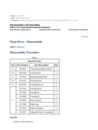
Final Drive - Disassemble
SMCS - 4050-015
Disassembly Procedure
Table 1
Required Tools
Tool Part Number Part Description Qty
A 1P-2420 Transmission Repair Stand 1
B 439-3938 Link Bracket 2
C 1P-1863 Retaining Ring Pliers 1
D 154-6181 Forcing Screw 2
E 439-3939 Link Bracket As 2
F
5F-7366 Forcing Screw 1
1P-5546 Crossblock 1
1U-9889 Crossblock 1
1P-0520 Driver Group 1
6V-7888 Puller Leg 2
1H-3112 Puller Assembly 1
1P-5551 Adjustable Screw Assembly 1
Start By:
a. Remove the final drive.
1/12
538 Forest Machine General Forestry GMY00001-UP (MACHINE) POWERED BY C...
2021/2/9
https://127.0.0.1/sisweb/sisweb/techdoc/techdoc_print_page.jsp?returnurl=/sisw...
2. Note: Cleanliness is an important factor. Before the disassembly procedure, the exterior of
the component should be thoroughly cleaned. This will prevent dirt from entering the
internal mechanism.
Note: Some of the images that are in this procedure do not show the sprocket assembly that
is attached to the final drive housing. If necessary, the weights that are given include the
weight of the sprocket assembly.
1. Put an alignment mark across the sections of the final drive for assembly purposes. The
parts must be reinstalled in the original locations.
Illustration 1 g01751055
2. Position final drive (3) to Tooling (A). The weight of final drive (3) is approximately 365 kg
(785 lb).
3. Remove bolts (2) that hold cover (1) in position.
Illustration 2 g01751153
4. Remove the setscrews from cover (1).
5. Attach Tooling (B) and a suitable lifting device to cover (1). The weight of cover (1) is
approximately 32 kg (70 lb).
6. Remove cover (1).
2/12
538 Forest Machine General Forestry GMY00001-UP (MACHINE) POWERED BY C...
2021/2/9
https://127.0.0.1/sisweb/sisweb/techdoc/techdoc_print_page.jsp?returnurl=/sisw...
3. Illustration 3 g01760156
7. Remove bolts (4) and gear (6).
8. Check plate (7). Replace plate (7) if wear is shown.
9. Remove plugs (5) from cover (1).
Illustration 4 g01760155
10. Remove O-ring seal (8) from plugs (5).
Illustration 5 g01760169
11. Remove gear (9) and spacer (10).
3/12
538 Forest Machine General Forestry GMY00001-UP (MACHINE) POWERED BY C...
2021/2/9
https://127.0.0.1/sisweb/sisweb/techdoc/techdoc_print_page.jsp?returnurl=/sisw...
4. Illustration 6 g01760152
12. Use Tooling (C) to remove retaining ring (11).
13. Remove washer (12) and gear (13).
14. Remove bearing assembly (14) and second washer (12).
15. Repeat Steps 12 through 14 for the remaining two gear assemblies.
Illustration 7 g01760149
16. Remove retaining ring (15).
4/12
538 Forest Machine General Forestry GMY00001-UP (MACHINE) POWERED BY C...
2021/2/9
https://127.0.0.1/sisweb/sisweb/techdoc/techdoc_print_page.jsp?returnurl=/sisw...
5. Illustration 8 g01760143
17. Remove carrier assembly (16).
Illustration 9 g01760162
18. Use a suitable press to remove shafts (17) from carrier assembly (16).
Illustration 10 g01760150
19. Remove gear (18) and spacer (19).
5/12
538 Forest Machine General Forestry GMY00001-UP (MACHINE) POWERED BY C...
2021/2/9
https://127.0.0.1/sisweb/sisweb/techdoc/techdoc_print_page.jsp?returnurl=/sisw...
6. Illustration 11 g01760170
20. Remove retaining ring (20) and carrier assembly (21).
Illustration 12 g01760159
21. Disassemble carrier assembly (21), as follows.
a. Use a suitable hammer and a suitable punch to drive spring pin (22) into planetary
shaft (23).
Illustration 13 g01760168
b. Remove planetary shaft (23).
6/12
538 Forest Machine General Forestry GMY00001-UP (MACHINE) POWERED BY C...
2021/2/9
https://127.0.0.1/sisweb/sisweb/techdoc/techdoc_print_page.jsp?returnurl=/sisw...
7. c. Use a suitable hammer and a suitable punch to remove spring pin (22) from planetary
shaft (23).
Illustration 14 g01760153
d. Remove thrust washers (24) and planetary gear (26) from the carrier assembly.
e. Remove bearing (25) from planetary gear (26).
22. Repeat Steps 21.a through 21.e for the other two planetary gears.
Illustration 15 g01760166
23. Remove gear (27) and spacer (28).
7/12
538 Forest Machine General Forestry GMY00001-UP (MACHINE) POWERED BY C...
2021/2/9
https://127.0.0.1/sisweb/sisweb/techdoc/techdoc_print_page.jsp?returnurl=/sisw...
8. Illustration 16 g01760164
24. Use two people to remove carrier assembly (29). The weight of carrier assembly (29) is
approximately 38 kg (85 lb).
Illustration 17 g01760160
25. Disassemble carrier assembly (29), as follows.
a. Use a suitable hammer and a suitable punch to drive spring pin (31) into planetary
shaft (30).
Illustration 18 g01760161
b. Remove planetary shaft (30).
c. Use a suitable hammer and a suitable punch to remove spring pin (31) from planetary
shaft (30).
8/12
538 Forest Machine General Forestry GMY00001-UP (MACHINE) POWERED BY C...
2021/2/9
https://127.0.0.1/sisweb/sisweb/techdoc/techdoc_print_page.jsp?returnurl=/sisw...
9. Illustration 19 g01760167
d. Remove thrust washers (32) and planetary gear (34) from the carrier assembly.
e. Remove bearings (33) from planetary gear (34).
26. Repeat Steps 25.a through 25.e for the other two planetary gears.
Illustration 20 g01760259
27. Use two people to remove ring gear (35). The weight of ring gear (35) is approximately
41 kg (90 lb).
Illustration 21 g01760357
9/12
538 Forest Machine General Forestry GMY00001-UP (MACHINE) POWERED BY C...
2021/2/9
https://127.0.0.1/sisweb/sisweb/techdoc/techdoc_print_page.jsp?returnurl=/sisw...
10. 28. Remove O-ring seal (36).
Illustration 22 g01760374
29. Remove bolts (37) from coupling gear (38).
Illustration 23 g01760397
30. Use Tooling (D) to remove coupling gear (38) from housing (39).
Illustration 24 g01760477
31. Remove shims (40).
10/12
538 Forest Machine General Forestry GMY00001-UP (MACHINE) POWERED B...
2021/2/9
https://127.0.0.1/sisweb/sisweb/techdoc/techdoc_print_page.jsp?returnurl=/sisw...
11. Illustration 25 g01760493
32. Attach Tooling (E) and a suitable lifting device to housing (39). The combined weight of
housing (39) and the final drive sprocket is approximately 82 kg (180 lb).
33. Use a suitable hammer and a suitable punch to separate housing (39) and the final drive
sprocket from the motor housing (41).
Illustration 26 g01760513
34. Remove Duo-Cone seal (43) from motor housing (41).
35. Remove dowel pins (42).
Illustration 27 g01760573
11/12
538 Forest Machine General Forestry GMY00001-UP (MACHINE) POWERED B...
2021/2/9
https://127.0.0.1/sisweb/sisweb/techdoc/techdoc_print_page.jsp?returnurl=/sisw...
12. Illustration 28 g01760574
36. Remove Duo-Cone seal (45) from housing (39).
37. Use Tooling (F) to remove bearings (44) and (46) from housing (39).
38. If necessary, remove the sprocket.
12/12
538 Forest Machine General Forestry GMY00001-UP (MACHINE) POWERED B...
2021/2/9
https://127.0.0.1/sisweb/sisweb/techdoc/techdoc_print_page.jsp?returnurl=/sisw...
13. Product: EXCAVATOR
Model: 538 EXCAVATOR GMY
Configuration: 538 Forest Machine General Forestry GMY00001-UP (MACHINE) POWERED BY C7.1 Engine
Disassembly and Assembly
538 LL GF Forest Machine Machine Systems
Media Number -M0071454-01 Publication Date -01/08/2017 Date Updated -02/08/2017
i06723435
Final Drive - Assemble
SMCS - 4050-016
Assembly Procedure
Table 1
Required Tools
Tool Part Number Part Description Qty
A 1P-2420 Transmission Repair Stand 1
B 439-3938 Link Bracket 2
C 1P-1863 Retaining Ring Pliers 1
E 439-3939 Link Bracket As 2
G 1U-5933 Duo-Cone Seal Installer As 1
H - Loctite C5A Copper Anti-Seize -
J - Loctite 5188 -
K 369-9451 Grease -
L - Loctite 243 -
M FT-2770 Leak Down Test Tool 1
Note: Cleanliness is an important factor. Before assembly, all parts should be thoroughly cleaned
in cleaning fluid. Allow the parts to air dry. Wiping cloths or rags should not be used to dry parts.
Lint may be deposited on the parts which may cause later trouble. Inspect all parts. If any parts are
worn or damaged, use new parts for replacement. All disassembly and all assembly procedures
must be performed on a clean work surface and in a clean hydraulic area. Always keep cleaned
parts covered and protected.
1/16
538 Forest Machine General Forestry GMY00001-UP (MACHINE) POWERED BY C...
2021/2/9
https://127.0.0.1/sisweb/sisweb/techdoc/techdoc_print_page.jsp?returnurl=/sisw...
14. Note: O-rings, gaskets, and seals should always be replaced. A used O-ring may not have the
same sealing properties as a new O-ring. Use Tooling (K) during the assembly procedure.
Note: Apply a light film of hydraulic oil to all components before assembly.
1. If necessary, install the sprocket.
Illustration 1 g01760833
2. Lower the temperature of bearings (44) and (46).
3. Use a suitable press to install bearings (44) and (46). Make sure that bearings (44) and (46)
contact the counterbore in housing (39).
4. Use the following procedure to preload the bearings and determine the correct thickness of
shims.
Illustration 2 g01760875
a. Attach Tooling (E) and a suitable lifting device to housing (39). Install housing (39)
onto motor housing (41).
b. Position housing (39) and motor housing (41) onto a suitable press. The combined
weight of housing (39) and motor housing (41) is approximately 82 kg (180 lb).
2/16
538 Forest Machine General Forestry GMY00001-UP (MACHINE) POWERED BY C...
2021/2/9
https://127.0.0.1/sisweb/sisweb/techdoc/techdoc_print_page.jsp?returnurl=/sisw...
15. Illustration 3 g01760892
(a) Bearing surface
(b) Housing surface
c. Use a suitable press and a spacer to apply a load of 4000 kg (8820 lb) on the bearings.
Rotate the housing to seat the bearings.
d. Reduce the load on the bearings to 1000 ± 100 kg (2200 ± 220 lb).
e. Use a depth micrometer to measure the step length between the bearing surface and
the housing surface. Take measurements at several different locations around the
housing. Compute the average of the measured dimensions and record the number.
Call this Dimension (Y).
Illustration 4 g01761534
f. Use a depth micrometer to measure the step length of coupling gear (38). Take
measurements at several different locations around coupling gear (38). Compute the
average of the measured dimensions and record the number. Call this Dimension (X).
g. The thickness of the shims is equal to (X − Y) ± 0.05 mm (0.002 inch).
Note: Use no more than two shims. If two shims are required, install the thinner shim
next to coupling gear (38).
3/16
538 Forest Machine General Forestry GMY00001-UP (MACHINE) POWERED BY C...
2021/2/9
https://127.0.0.1/sisweb/sisweb/techdoc/techdoc_print_page.jsp?returnurl=/sisw...
16. Illustration 5 g01760875
h. Use Tooling (E) and the suitable lifting device to remove housing (39) from motor
housing (41).
Illustration 6 g01761876
Note: The rubber seals and sealing surfaces must be clean and dry. Apply a thin film of
clean SAE 30 oil on the contact surfaces of the metal seals prior to assembly.
5. Use Tooling (G) to install Duo-Cone seal (45) in housing (39). Refer to Disassembly and
Assembly, "Duo-Cone Conventional Seals - Install".
Illustration 7 g01761954
4/16
538 Forest Machine General Forestry GMY00001-UP (MACHINE) POWERED BY C...
2021/2/9
https://127.0.0.1/sisweb/sisweb/techdoc/techdoc_print_page.jsp?returnurl=/sisw...
17. 6. Use Tooling (G) to install Duo-Cone seal (43) in motor housing (41).
Illustration 8 g01760513
7. Apply Tooling (H) to the surfaces that contact dowel pins (42).
8. Install dowel pins (42).
Illustration 9 g01760875
Note: Do not damage the Duo-Cone seals in the housing or in motor housing (41) during
the assembly of the two components. After installation of the housing on motor housing
(41), there will be a small gap between the components. The gap is caused by the Duo-Cone
seals. This gap will be eliminated during installation of coupling gear (26) (not shown).
9. Attach Tooling (E) and a suitable lifting device to housing (39). The combined weight of
housing (39) and the final drive sprocket is approximately 82 kg (180 lb).
10. Install housing (39) on motor housing (41).
5/16
538 Forest Machine General Forestry GMY00001-UP (MACHINE) POWERED BY C...
2021/2/9
https://127.0.0.1/sisweb/sisweb/techdoc/techdoc_print_page.jsp?returnurl=/sisw...
18. Illustration 10 g01760477
11. Install shims (40) that were determined in Step 4.g in the housing.
Note: If two shims are required, install the thinner shim next to the coupling gear.
Illustration 11 g01760374
12. Install coupling gear (38).
13. Apply Tooling (L) to the clean threads and dry threads of bolts (37).
14. Install bolts (37) in an even pattern until coupling gear (38) is seated against the bearing.
Tighten bolts (37) in a crisscross pattern to a torque of 570 ± 80 N·m (420 ± 60 lb ft).
6/16
538 Forest Machine General Forestry GMY00001-UP (MACHINE) POWERED BY C...
2021/2/9
https://127.0.0.1/sisweb/sisweb/techdoc/techdoc_print_page.jsp?returnurl=/sisw...
19. Illustration 12 g01760357
15. Install O-ring seal (36).
Illustration 13 g01760259
16. Use two people to install ring gear (35). The weight of ring gear (35) is approximately 41 kg
(90 lb).
Illustration 14 g01760160
Illustration 15 g01760167
7/16
538 Forest Machine General Forestry GMY00001-UP (MACHINE) POWERED BY C...
2021/2/9
https://127.0.0.1/sisweb/sisweb/techdoc/techdoc_print_page.jsp?returnurl=/sisw...
20. Illustration 16 g01762255
17. Assemble carrier assembly (29), as follows.
a. Install bearings (33) in planetary gear (34).
b. Install thrust washers (32) and planetary gear (34) in carrier assembly (29).
c. Use a deburring tool to remove the metal burr from the openings in the carrier. Install
planetary shaft (30) in carrier assembly (29).
d. Align the split in spring pin (31) to the top or the bottom of the carrier. Make a stake
mark on each side of the spring pin hole. Dimension (AA) indicates the location of
the stake marks. Dimension (AA) is 2.25 ± 0.75 mm (0.089 ± 0.030 inch) from the
outside diameter of the spring pin hole to the stake.
e. Use a suitable hammer and a suitable punch to drive spring pin (31) into planetary
shaft (30).
f. Repeat Steps 17.a through 17.d to install the other two planetary gears in the carrier.
Illustration 17 g01760164
8/16
538 Forest Machine General Forestry GMY00001-UP (MACHINE) POWERED BY C...
2021/2/9
https://127.0.0.1/sisweb/sisweb/techdoc/techdoc_print_page.jsp?returnurl=/sisw...
21. 18. Use two people to install carrier assembly (29). The weight of carrier assembly (29) is
approximately 39 kg (85 lb).
Illustration 18 g01760166
19. Install spacer (28) and gear (27).
Illustration 19 g01760159
Illustration 20 g01760153
9/16
538 Forest Machine General Forestry GMY00001-UP (MACHINE) POWERED BY C...
2021/2/9
https://127.0.0.1/sisweb/sisweb/techdoc/techdoc_print_page.jsp?returnurl=/sisw...
22. Illustration 21 g01758493
20. Assemble carrier assembly (21), as follows.
a. Install bearing (25) in planetary gear (26).
b. Install thrust washers (24) and planetary gear (26) in carrier assembly (21).
c. Use a deburring tool to remove the metal burr from the openings in the carrier. Install
planetary shaft (23) in carrier assembly (21).
d. Align the split in spring pin (22) to the top or the bottom of the carrier. Make a stake
mark on each side of the spring pin hole. Dimension (BB) indicates the location of the
stake marks. Dimension (BB) is 2.25 ± 0.75 mm (0.089 ± 0.030 inch) from the
outside diameter of the spring pin hole to the stake.
e. Use a suitable hammer and a suitable punch to drive spring pin (22) into planetary
shaft (23).
f. Repeat Steps 20.a through 20.d for the other two planetary gears in the carrier.
Illustration 22 g01760663
10/16
538 Forest Machine General Forestry GMY00001-UP (MACHINE) POWERED B...
2021/2/9
https://127.0.0.1/sisweb/sisweb/techdoc/techdoc_print_page.jsp?returnurl=/sisw...
23. 21. Install carrier assembly (21) into ring gear (35).
22. Install retaining ring (20).
Illustration 23 g01760645
23. Install spacer (19) and gear (18).
Illustration 24 g01760655
Note: Make sure that the oil passages in shafts (17) are oriented toward the center of carrier
assembly (16).
11/16
538 Forest Machine General Forestry GMY00001-UP (MACHINE) POWERED B...
2021/2/9
https://127.0.0.1/sisweb/sisweb/techdoc/techdoc_print_page.jsp?returnurl=/sisw...
24. 24. Raise the temperature of carrier assembly (16). Lower the temperature of (17) shafts. Install
shafts (17) into carrier assembly (16) until the groove of shafts (17) is at Dimension (A).
Dimension (A) equals 21.70 ± 0.10 mm (0.854 ± 0.004 inch).
25. Make eight stake marks at distance of Dimension (C) from each shaft (17). Dimension (C)
equals 2.0 ± 1.0 mm (0.08 ± 0.04 inch). The width of each stake mark should be equal to
Dimension (B). Dimension (B) equals 4.0 ± 1.0 mm (0.16 ± 0.04 inch).
Illustration 25 g01760651
26. Assemble carrier assembly (16), as follows.
a. Install carrier assembly in position on gear (18).
Illustration 26 g01760641
b. Install retaining ring (15) onto gear (18).
12/16
538 Forest Machine General Forestry GMY00001-UP (MACHINE) POWERED B...
2021/2/9
https://127.0.0.1/sisweb/sisweb/techdoc/techdoc_print_page.jsp?returnurl=/sisw...
25. Illustration 27 g01760647
c. Install washer (12) and bearing assembly (14).
d. Install gear (13) and second washer (12).
e. Use Tooling (C) to install retaining ring (11).
f. Repeat Steps 26.a through 26.e for the other two planetary gears.
Illustration 28 g01760669
27. Install spacer (10) and gear (9).
Illustration 29 g01760650
13/16
538 Forest Machine General Forestry GMY00001-UP (MACHINE) POWERED B...
2021/2/9
https://127.0.0.1/sisweb/sisweb/techdoc/techdoc_print_page.jsp?returnurl=/sisw...
26. 28. Install O-ring seal (8) on plugs (5).
Illustration 30 g01760653
29. Install plugs (5) in cover (1). Install one 8.00 mm (0.315 inch) plate (7).
30. Position gear (6) and install bolts (4).
Illustration 31 g01751153
Illustration 32 g01751055
31. Place a piece of solder in the center of gear (9) (not shown).
14/16
538 Forest Machine General Forestry GMY00001-UP (MACHINE) POWERED B...
2021/2/9
https://127.0.0.1/sisweb/sisweb/techdoc/techdoc_print_page.jsp?returnurl=/sisw...
27. Suggest:
If the above button click is invalid.
Please download this document
first, and then click the above link
to download the complete manual.
Thank you so much for reading
28. Note: You may need to apply some grease to the solder to keep the solder in position on
gear (9).
32. Use Tooling (B) and a suitable lifting device to install cover (1). The weight of cover (1) is
approximately 32 kg (70 lb).
33. Install four bolts (2) at 90 degrees from each other. Tighten bolts (2) in a crisscross pattern
to a torque of 420 ± 60 N·m (310 ± 44 lb ft). Turn bolts (2) and additional 60 ± 5 degrees.
34. Remove bolts (2).
35. Use Tooling (B) and a suitable lifting device to remove cover (1). The weight of cover (1) is
approximately 32 kg (70 lb).
36. Use a micrometer to measure the thickness of the solder. Record this measurement to
determine the required thickness of plates (7). Adjust plates (7) to obtain a clearance of
1.000 + 1.000 mm (0.0394 + 0.0394 inch) between plate (7) and gear (9).
37. Apply Tooling (J) to the mating surfaces of cover (1) and the housing.
38. Use Tooling (B) and a suitable lifting device to install cover (1). The weight of cover (1) is
approximately 32 kg (70 lb).
39. Install bolts (2). Tighten bolts (2) in a crisscross pattern to a torque of 420 ± 60 N·m
(310 ± 44 lb ft). Turn bolts (2) and additional 60 ± 5 degrees.
Illustration 33 g06092181
40. Remove plug (5) (not shown). Attach Tooling (M) to the cover. Reduce the air pressure at
the source to 103 kPa (15 psi). Apply air pressure to Tooling (M). This air will test the Duo-
Cone seals.
41. Use the ball valve on Tooling (M) to eliminate the air pressure to the final drive. A pressure
of 98 kPa (14.2 psi) must be maintained for 30 seconds.
42. Remove Tooling (M). Install plug (5) (not shown). Tighten plug (5) to a torque of
80 ± 10 N·m (59 ± 7 lb ft).
43. Remove the final drive from Tooling (A). The weight of the final drive assembly is
approximately 365 kg (785 lb).
15/16
538 Forest Machine General Forestry GMY00001-UP (MACHINE) POWERED B...
2021/2/9
https://127.0.0.1/sisweb/sisweb/techdoc/techdoc_print_page.jsp?returnurl=/sisw...