The document provides step-by-step instructions for disassembling and assembling the final drives of a 350L excavator. Key steps include removing the final drives and travel motors, disassembling the internal components of the final drives which include multiple planetary gear sets, carriers, and a sun gear, and then reassembling the final drives in reverse order. Proper cleaning, application of lubricants, and torque specifications are noted throughout to ensure correct reassembly.
Core technology of Hyundai Motor Group's EV platform 'E-GMP'Hyundai Motor Group
What’s the force behind Hyundai Motor Group's EV performance and quality?
Maximized driving performance and quick charging time through high-density battery pack and fast charging technology and applicable to various vehicle types!
Discover more about Hyundai Motor Group’s EV platform ‘E-GMP’!
𝘼𝙣𝙩𝙞𝙦𝙪𝙚 𝙋𝙡𝙖𝙨𝙩𝙞𝙘 𝙏𝙧𝙖𝙙𝙚𝙧𝙨 𝙞𝙨 𝙫𝙚𝙧𝙮 𝙛𝙖𝙢𝙤𝙪𝙨 𝙛𝙤𝙧 𝙢𝙖𝙣𝙪𝙛𝙖𝙘𝙩𝙪𝙧𝙞𝙣𝙜 𝙩𝙝𝙚𝙞𝙧 𝙥𝙧𝙤𝙙𝙪𝙘𝙩𝙨. 𝙒𝙚 𝙝𝙖𝙫𝙚 𝙖𝙡𝙡 𝙩𝙝𝙚 𝙥𝙡𝙖𝙨𝙩𝙞𝙘 𝙜𝙧𝙖𝙣𝙪𝙡𝙚𝙨 𝙪𝙨𝙚𝙙 𝙞𝙣 𝙖𝙪𝙩𝙤𝙢𝙤𝙩𝙞𝙫𝙚 𝙖𝙣𝙙 𝙖𝙪𝙩𝙤 𝙥𝙖𝙧𝙩𝙨 𝙖𝙣𝙙 𝙖𝙡𝙡 𝙩𝙝𝙚 𝙛𝙖𝙢𝙤𝙪𝙨 𝙘𝙤𝙢𝙥𝙖𝙣𝙞𝙚𝙨 𝙗𝙪𝙮 𝙩𝙝𝙚 𝙜𝙧𝙖𝙣𝙪𝙡𝙚𝙨 𝙛𝙧𝙤𝙢 𝙪𝙨.
Over the 10 years, we have gained a strong foothold in the market due to our range's high quality, competitive prices, and time-lined delivery schedules.
Symptoms like intermittent starting and key recognition errors signal potential problems with your Mercedes’ EIS. Use diagnostic steps like error code checks and spare key tests. Professional diagnosis and solutions like EIS replacement ensure safe driving. Consult a qualified technician for accurate diagnosis and repair.
Things to remember while upgrading the brakes of your carjennifermiller8137
Upgrading the brakes of your car? Keep these things in mind before doing so. Additionally, start using an OBD 2 GPS tracker so that you never miss a vehicle maintenance appointment. On top of this, a car GPS tracker will also let you master good driving habits that will let you increase the operational life of your car’s brakes.
5 Warning Signs Your BMW's Intelligent Battery Sensor Needs AttentionBertini's German Motors
IBS monitors and manages your BMW’s battery performance. If it malfunctions, you will have to deal with an array of electrical issues in your vehicle. Recognize warning signs like dimming headlights, frequent battery replacements, and electrical malfunctions to address potential IBS issues promptly.
What Exactly Is The Common Rail Direct Injection System & How Does It WorkMotor Cars International
Learn about Common Rail Direct Injection (CRDi) - the revolutionary technology that has made diesel engines more efficient. Explore its workings, advantages like enhanced fuel efficiency and increased power output, along with drawbacks such as complexity and higher initial cost. Compare CRDi with traditional diesel engines and discover why it's the preferred choice for modern engines.
Comprehensive program for Agricultural Finance, the Automotive Sector, and Empowerment . We will define the full scope and provide a detailed two-week plan for identifying strategic partners in each area within Limpopo, including target areas.:
1. Agricultural : Supporting Primary and Secondary Agriculture
• Scope: Provide support solutions to enhance agricultural productivity and sustainability.
• Target Areas: Polokwane, Tzaneen, Thohoyandou, Makhado, and Giyani.
2. Automotive Sector: Partnerships with Mechanics and Panel Beater Shops
• Scope: Develop collaborations with automotive service providers to improve service quality and business operations.
• Target Areas: Polokwane, Lephalale, Mokopane, Phalaborwa, and Bela-Bela.
3. Empowerment : Focusing on Women Empowerment
• Scope: Provide business support support and training to women-owned businesses, promoting economic inclusion.
• Target Areas: Polokwane, Thohoyandou, Musina, Burgersfort, and Louis Trichardt.
We will also prioritize Industrial Economic Zone areas and their priorities.
Sign up on https://profilesmes.online/welcome/
To be eligible:
1. You must have a registered business and operate in Limpopo
2. Generate revenue
3. Sectors : Agriculture ( primary and secondary) and Automative
Women and Youth are encouraged to apply even if you don't fall in those sectors.
In this presentation, we have discussed a very important feature of BMW X5 cars… the Comfort Access. Things that can significantly limit its functionality. And things that you can try to restore the functionality of such a convenient feature of your vehicle.
"Trans Failsafe Prog" on your BMW X5 indicates potential transmission issues requiring immediate action. This safety feature activates in response to abnormalities like low fluid levels, leaks, faulty sensors, electrical or mechanical failures, and overheating.
Why Is Your BMW X3 Hood Not Responding To Release CommandsDart Auto
Experiencing difficulty opening your BMW X3's hood? This guide explores potential issues like mechanical obstruction, hood release mechanism failure, electrical problems, and emergency release malfunctions. Troubleshooting tips include basic checks, clearing obstructions, applying pressure, and using the emergency release.
Ever been troubled by the blinking sign and didn’t know what to do?
Here’s a handy guide to dashboard symbols so that you’ll never be confused again!
Save them for later and save the trouble!
Fleet management these days is next to impossible without connected vehicle solutions. Why? Well, fleet trackers and accompanying connected vehicle management solutions tend to offer quite a few hard-to-ignore benefits to fleet managers and businesses alike. Let’s check them out!
1. Product: EXCAVATOR
Model: 350 L EXCAVATOR 9DK
Configuration: 350, 350L TRACK-TYPE EXCAVATORS 9DK00301-UP (MACHINE) POWERED BY 3306 ENGINE
Disassembly and Assembly
350 AND 350 L EXCAVATOR MACHINE SYSTEMS
Media Number -SENR6148-04 Publication Date -01/11/2004 Date Updated -12/03/2010
SENR61480032
Final Drives
SMCS - 4050-017
Disassemble & Assemble Final Drives
Start By:
a. remove final drives and travel motors
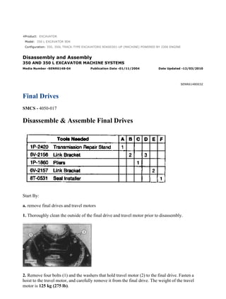
1. Thoroughly clean the outside of the final drive and travel motor prior to disassembly.
2. Remove four bolts (1) and the washers that hold travel motor (2) to the final drive. Fasten a
hoist to the travel motor, and carefully remove it from the final drive. The weight of the travel
motor is 125 kg (275 lb).
1/19(W)
w
2022/3/8
https://127.0.0.1/sisweb/sisweb/techdoc/techdoc_print_page.jsp?returnurl=/sisweb/siswe...
2. 3. Remove O-ring seal (3) and coupler (4) from the final drive.
4. Fasten a hoist to the final drive, and turn it over 180 degrees. The weight of the final drive is
469 kg (1035 lb).
5. Fasten the final drive to Tool (A) as shown. Put an alignment mark across the sections of the
final drive for assembly purposes. The parts must be reinstalled in their original locations.
6. Remove two setscrews (5) from the cover assembly of the final drive.
7. Fasten Tool (B) and a hoist to cover assembly (7) as shown.
8. Remove 20 bolts (6) and the washers that hold the cover assembly in place.
9. Using a soft faced hammer, break the seal between cover assembly (7) and the ring gear.
Remove the cover assembly. The weight of the cover assembly is 52 kg (115 lb).
2/19(W)
w
2022/3/8
https://127.0.0.1/sisweb/sisweb/techdoc/techdoc_print_page.jsp?returnurl=/sisweb/siswe...
3. 10. Remove spacer (8) from the cover.
11. Remove shim(s) (9) from the cover.
12. Remove 10 socket head bolts (10) and ring gear (11) from the cover.
13. Remove sun gear (12). Remove carrier assembly (13) by lifting it straight up.
14. Disassemble carrier assembly (13) as follows:
a. Remove two spacers (14). A spacer is located on each side of the sun gear in carrier assembly
(13).
NOTE: Planetary gears (17) have identification grooves (L) on them. Note the position of the
identification grooves in relation to the carrier for assembly purposes.
3/19(W)
w
2022/3/8
https://127.0.0.1/sisweb/sisweb/techdoc/techdoc_print_page.jsp?returnurl=/sisweb/siswe...
4. b. Remove retaining ring (15) with Tool (C). Remove two thrust washers (16) and planetary gear
(17) from the carrier. Remove bearing (18) from the planetary gear.
c. Remove the other two planetary gears from the carrier as in Step 14b.
d. Using a screwdriver, remove retaining ring (19) from the carrier. Remove sun gear (20) from
the carrier.
15. Fasten Tool (D) and a hoist to carrier assembly (21) as shown. Remove carrier assembly (21)
by pulling it straight up. The weight of the carrier assembly is 59 kg (130 lb).
16. Disassemble carrier assembly (21) as follows:
NOTE: Spacer (22) may remain with carrier assembly (21), or it may remain with carrier
assembly (30). See Step 17.
a. Remove spacer (22) from carrier assembly (21).
4/19(W)
w
2022/3/8
https://127.0.0.1/sisweb/sisweb/techdoc/techdoc_print_page.jsp?returnurl=/sisweb/siswe...
5. b. Drive spring pin (23) into planetary shaft (24) with a hammer and a punch.
NOTE: Planetary gears (26) have identification grooves (M) on them. Note the position of the
identification grooves in relation to the carrier for assembly purposes.
c. Remove planetary shaft (24), two thrust washers (25) and planetary gear (26) from the carrier.
Remove bearing (27) from the planetary gear. Remove spring pin (23) from planetary shaft (24)
with a hammer and a punch.
d. Remove the other two planetary gears from the carrier as in Steps 16b and 16c.
e. Using a screwdriver, remove retaining ring (28). Remove sun gear (29) from the carrier.
5/19(W)
w
2022/3/8
https://127.0.0.1/sisweb/sisweb/techdoc/techdoc_print_page.jsp?returnurl=/sisweb/siswe...
6. 17. If spacer (22) was not removed in Step 16a remove it from carrier assembly (30) at this time.
18. Fasten Tool (B) and a hoist to carrier assembly (30) as shown. Remove the carrier assembly.
The weight of the carrier assembly is 79 kg (175 lb).
19. Disassemble carrier assembly (30) as follows:
a. Drive spring pin (31) into planetary shaft (32) with a hammer and a punch.
NOTE: Planetary gears (34) have identification grooves (N) on them. Note the position of the
identification grooves in relation to the carrier for assembly purposes.
b. Remove planetary shaft (32), two thrust washers (33) and planetary gear (34) from the carrier.
Remove two bearings (35) from the planetary gear. Drive spring pin (31) out of planetary shaft
(32) with a hammer and a punch.
c. Remove the other three planetary gears from the carrier as in Steps 19a and 19b.
20. Fasten Tool (B) and a hoist to ring gear (36) as shown. Remove the ring gear from main
housing (37). The weight of the ring gear is 91 kg (200 lb).
6/19(W)
w
2022/3/8
https://127.0.0.1/sisweb/sisweb/techdoc/techdoc_print_page.jsp?returnurl=/sisweb/siswe...
7. 21. Remove O-ring seal (38) from main housing (37).
22. Remove 12 bolts (39) from gear (40).
23. Install three suitable size forcing bolts (41) in gear (40) as shown. Tighten the three forcing
bolts evenly to loosen gear (40). Remove the gear from the main housing.
24. Remove shims (42) from the main housing.
7/19(W)
w
2022/3/8
https://127.0.0.1/sisweb/sisweb/techdoc/techdoc_print_page.jsp?returnurl=/sisweb/siswe...
8. 25. Fasten Tool (E) and a hoist to main housing (37) as shown. Separate the main housing from
the motor housing. The weight of the main housing is 132 kg (290 lb).
26. If necessary, remove six locating pins (43) from the motor housing.
27. Remove Duo-Cone seal (44) from the motor housing.
28. Remove Duo-Cone seal (45) from the main housing.
29. Remove two bearings (46) from the main housing.
NOTE: The following steps are for the assembly of the final drives.
30. Make sure all parts of the final drive are thoroughly clean and free of dirt and debris prior to
assembly. Check the condition of all O-ring seals used in the final drive. If any of the seals are
damaged, use new parts for replacement. Reassemble the final drive on Tool (A).
8/19(W)
w
2022/3/8
https://127.0.0.1/sisweb/sisweb/techdoc/techdoc_print_page.jsp?returnurl=/sisweb/siswe...
9. 31. Apply a thin coat of 5P-3931 High Temperature Anti-Seize Compound to the surfaces
inside the main housing that make contact with bearings (46). Install bearings (46) in the main
housing with a press. Install the bearings until each one makes contact with the counterbore in the
main housing.
32. Fasten Tool (E) and a hoist to main housing (37) as shown. Install the main housing on the
motor housing.
33. Adjust the bearing preload of the final drive. Determine the correct amount of shims (42)
required for the proper bearing preload as follows:
a. Using a depth micrometer, measure the step height of gear (40) at several locations around the
gear. Find the average of the dimensions measured, and record it. Call it dimension (X).
b. Apply a load of 10000 kg (22000 lb) to outer race of bearing (46).
c. Rotate main housing (37) several times to seat the bearings.
d. Reduce the load to 3500 ± 350 kg (7700 ± 770 lb).
9/19(W)
w
2022/3/8
https://127.0.0.1/sisweb/sisweb/techdoc/techdoc_print_page.jsp?returnurl=/sisweb/siswe...
10. e. With the load still on the bearings, measure the distance between the top face of the motor
housing and the top face of bearing (46). Do this in several locations around the motor housing.
Find the average of the dimensions measured, and record it. Call it dimension (Y).
f. Determine the correct shim thickness [made up of one or two shims (42)] to be used between
bearing (46) and gear (40). The shim thickness is equal to (Y) - (X) ± 0.05 mm (.002 in).
NOTE: If two shims (42) are required, install the thinnest shim next to gear (40) during final
assembly.
34. Fasten Tool (E) and a hoist to main housing (37) as shown. Separate the main housing from
the motor housing.
NOTICE
See the topic "Assembly And Installation Of Conventional Duo-Cone
Seals" in this module.
NOTE: The rubber seals and all surfaces that make contact with the seals must be clean and dry.
After installation of the seals, put clean SAE 30 oil on the contact surfaces of the metal seals.
35. Install Duo-Cone seal (45) in the main housing with Tool (F).
10/19(W)
w
2022/3/8
https://127.0.0.1/sisweb/sisweb/techdoc/techdoc_print_page.jsp?returnurl=/sisweb/siswe...
11. 36. Install Duo-Cone seal (44) in the motor housing with Tool (F).
37. Apply a thin coat of 5P-3931 High Temperature Anti-Seize Compound to the six locating
pin bores in the motor housing. Reinstall six locating pins (43) in the motor housing.
NOTICE
Do not scratch or damage the Duo-Cone seals in the main housing or
the motor housing during assembly of these two components. After
installation of the main housing on the motor housing, there will be a
small gap between the components. The gap is caused by the Duo-Cone
seals and will be eliminated during installation of gear (40).
38. Fasten Tool (E) and a hoist to main housing (37) as shown. Install the main housing on the
motor housing.
39. Put shim pack (42) determined in Step 33a through 33f on bearing (46) as shown. If two shims
were required, make sure the thinnest shim is installed next to gear (40) when it is installed.
11/19(W)
w
2022/3/8
https://127.0.0.1/sisweb/sisweb/techdoc/techdoc_print_page.jsp?returnurl=/sisweb/siswe...
12. 40. Put gear (40) in its original position on the motor housing.
41. Put 9S-3263 Thread Lock on the threads of 12 bolts (3() that hold gear (40) in position.
Install the bolts, and tighten them evenly and in diagonally opposite pairs.
42. Install O-ring seal (38) in main housing (37).
43. Thoroughly clean the mating surface of main housing (37) that makes contact with ring gear
(36). Put a bead of 1U-8846 Gasket Maker on the mating surface of ring gear (36). Fasten Tool
(B) and a hoist to ring gear (36). Put the ring gear in position on the main housing. Make sure the
alignment mark on the main housing and the ring gear line up with each other.
44. Assemble carrier assembly (30) as follows:
12/19(W)
w
2022/3/8
https://127.0.0.1/sisweb/sisweb/techdoc/techdoc_print_page.jsp?returnurl=/sisweb/siswe...
13. NOTICE
Identification grooves (N) in planetary gears (34) must be facing
toward gear (40), after installation in carrier assembly (30).
a. Assemble carrier assembly (30). Put clean SAE 30 oil on bearings (35). Install two bearings
(35) in planetary gear (34). Install a thrust washer (33) on each side of the planetary gear. Install
the planetary gear and thrust washers in carrier (30). Make sure identification grooves (N) are
facing in the correct direction. Install planetary shaft (32) in carrier (30) and through planetary
gear (34). Make sure the spring pin hole in the planetary shaft is in alignment with the spring pin
hole in the carrier. Install spring pin (31) in the carrier and into the planetary shaft. Install the
spring pin until it is 2 to 3 mm (.078 to .118 in) below the outside surface of the carrier, and with
the split in the spring pin facing to either side in the carrier as shown in Illustration C28668P1. To
prevent the spring pin from falling out, make a stake mark on each side of the spring pin hole in
the carrier. Each stake mark should be approximately 1.5 to 3.00 mm (.59 to .118 in) from the
spring pin hole.
b. Install the other three planetary gears in carrier (30) as in Step 44a.
45. Fasten Tool (B) and a hoist to carrier assembly (30). Put the carrier assembly in position in
ring gear (36). It may be necessary to rotate the carrier assembly back and forth during installation
to ensure all gears engage properly.
46. Install spacer (22) on carrier assembly (30) as shown.
13/19(W)
w
2022/3/8
https://127.0.0.1/sisweb/sisweb/techdoc/techdoc_print_page.jsp?returnurl=/sisweb/siswe...
14. 47. Assemble carrier assembly (21) as follows:
NOTICE
14/19(W)
w
2022/3/8
https://127.0.0.1/sisweb/sisweb/techdoc/techdoc_print_page.jsp?returnurl=/sisweb/siswe...
15. Identification grooves (M) in planetary gears (26) must be facing the
same direction as noted during disassembly of carrier assembly (21).
a. Assemble carrier assembly (21). Install sun gear (29) in carrier (21). Make sure identification
grooves (M) are facing in the correct direction as noted during disassembly of the carrier
assembly. Using a screwdriver, install retaining ring (28) that holds the sun gear in the carrier. Put
clean SAE 30 oil on bearing (27). Install bearing (27) in planetary gear (26). Install a thrust
washer (25) on each side of the planetary gear. Install the thrust washers and the planetary gear in
carrier (21). Install planetary shaft (24) in carrier (21) and through planetary gear (26). Make sure
the spring pin hole in the carrier is in alignment with the spring pin hole in the planetary shaft.
Install spring pin (23) until it is 2 to 3 mm (.078 to .118 in) below the outside surface of the
carrier, and with the split in the spring pin facing to either side of the carrier as shown in
Illustration C28668P1. To prevent the spring pin from falling out, make a stake mark on each side
of the spring pin hole in the carrier. Each stake mark should be approximately 1.5 to 3.00 mm (.59
to .118 in) from the spring pin hole.
b. Install the other two planetary gears in carrier (21) as in Step 47a.
48. Fasten Tool (D) and a hoist to carrier assembly (21). Put the carrier assembly in position in
ring gear (36). It may be necessary to rotate the carrier assembly back and forth during installation
to ensure all gears engage properly.
49. Assemble carrier assembly (13) as follows:
15/19(W)
w
2022/3/8
https://127.0.0.1/sisweb/sisweb/techdoc/techdoc_print_page.jsp?returnurl=/sisweb/siswe...
16. NOTICE
Identification grooves (L) in planetary gears (17) must be facing in the
direction as noted during disassembly of carrier assembly (13). Also,
make sure retaining ring (15) is installed with the cross section of the
ring as shown in Illustration C28669P2.
a. Assemble carrier assembly (13). Install sun gear (20) in carrier (13) as shown in Photo
C47814P2. Using a screwdriver, install retaining ring (19) that holds the sun gear in the carrier.
Put clean SAE 30 oil on bearing (18), and install the bearing in planetary gear (17). Install a thrust
washer (16) on each side of the planetary gear. Install the planetary gear and thrust washers on the
shaft of carrier (13). Make sure identification grooves (L) are facing in the same direction as noted
during disassembly of carrier assembly (13). Using Tool (C), install retaining ring (15) to hold the
planetary gear in position. Make sure the retaining ring is installed with the cross section of the
ring as shown in Illustration C28669P2.
b. Install the other two planetary gears on carrier assembly (13) as in Step 49a.
50. Install a spacer (14) on each side of sun gear (20) in carrier assembly (13).
51. Install the spacers (14) and carrier assembly (13) in carrier assembly (21). Install sun gear (12)
in carrier assembly (13).
16/19(W)
w
2022/3/8
https://127.0.0.1/sisweb/sisweb/techdoc/techdoc_print_page.jsp?returnurl=/sisweb/siswe...
17. 52. Use a 25.4 mm (1.00 in) thick straight edge and depth micrometer to measure the distance
from the upper surface of sun gear (12) to the machined surface of ring gear (36). Record this
dimension. Call this dimension (P).
53. Use a 25.4 mm (1.00 in) straight edge and a depth micrometer to measure the distance from
the machined surface of cover (7) to the bottom of shim (8) insertion hole. Record this dimension.
Call this dimension (Q).
54. Determine the correct thickness of shim(s) (9). Shim(s) (9) control the amount of end play of
sun gear (12). The shim thickness is equal to dimension (Q) - (P) - 1.00 to 2.60 mm (.039
to .102 in).
55. Put ring gear (11) in position in cover (7). Make sure all of the mounting bolt holes in both
components are in alignment with each other. Put 9S-3263 Thread Lock on the threads of 10
socket head bolts (10) that hold ring gear (11) in place. Install the bolts, and tighten them evenly.
56. Install the correct thickness of shim(s) (9) in cover (7).
17/19(W)
w
2022/3/8
https://127.0.0.1/sisweb/sisweb/techdoc/techdoc_print_page.jsp?returnurl=/sisweb/siswe...
18. 57. Install spacer (8) in cover (7). It may be necessary to use a soft faced hammer to seat the
spacer.
58. Make sure the machined surface of ring gear (36) is thoroughly clean, free of dirt and debris
and is dry. Put a bead of 1U-8846 Gasket Maker around the machined surface of the ring gear.
Fasten Tool (B) and a hoist to cover assembly (7). Put the cover assembly in its original position
on the ring gear. It will be necessary to rotate the cover assembly back and forth to engage the
planetary gears of carrier assembly (13) with the ring gear in the cover assembly (7). Remove the
hoist and Tool (B) from the cover assembly. Reinstall two setscrews (5) in cover assembly (7).
59. Put a thin coat of 9S-3263 Thread Lock on the threads of 20 bolts (6) that hold cover
assembly (7) in position. Install the twenty washers and bolts. Tighten the bolts evenly.
60. Fasten a hoist to the final drive, and turn it over 180 degrees.
61. Install O-ring seal (3) and coupler (4) from the final drive.
62. Fasten a hoist to the travel motor, and carefully install it in the final drive. Install four bolts (1)
and the washers that hold travel motor (2) to the final drive.
End By:
a. install final drives and travel motors
18/19(W)
w
2022/3/8
https://127.0.0.1/sisweb/sisweb/techdoc/techdoc_print_page.jsp?returnurl=/sisweb/siswe...
19. Product: EXCAVATOR
Model: 350 L EXCAVATOR 9DK
Configuration: 350, 350L TRACK-TYPE EXCAVATORS 9DK00301-UP (MACHINE) POWERED BY 3306 ENGINE
Disassembly and Assembly
350 AND 350 L EXCAVATOR MACHINE SYSTEMS
Media Number -SENR6148-04 Publication Date -01/11/2004 Date Updated -12/03/2010
SENR61480033
Automatic Travel Speed Change Valve
SMCS - 3220-010; 3220-017
Remove & Install Automatic Travel Speed Change Valve
NOTE: The automatic travel speed change valve is located by the right side of the main frame
below the main control valve.
At operating temperature, the hydraulic oil tank is hot and under
pressure. Hot oil can cause burns. To prevent possible personal injury,
release the pressure in the implement hydraulic circuits (boom, stick
and bucket) before any hydraulic lines or components are disconnected
or removed.
1. Release the pressure in the hydraulic system as follows:
a. Fully retract the rod in the stick cylinder.
b. Adjust the position of the bucket so it will be flat on the ground when the boom is lowered.
c. Lower the boom until the bucket is flat on the ground.
d. Shut off the engine, and put the hydraulic activation control lever in the "Lock" position.
e. Move the control levers for the boom, bucket, stick and swing through their full travel strokes.
This will relieve any pressure that may be present in the pilot system.
f. Slowly loosen the air breather cap on the hydraulic oil tank to release the pressure.
g. Tighten the air breather cap on the hydraulic oil tank.
1/4(W)
w
2022/3/8
https://127.0.0.1/sisweb/sisweb/techdoc/techdoc_print_page.jsp?returnurl=/sisweb/siswe...
20. h. The pressure in the hydraulic system has now been released. Lines and components can now be
removed.
2. Disconnect hose assembly (1) and three hose assemblies (4) from the automatic travel speed
change valve. Put plugs in the ends of the hose assemblies to prevent oil loss and to keep dirt and
debris out of the hydraulic system.
3. Remove four bolts (2), the washers and automatic travel speed change valve (3).
NOTE: The following steps are for the installation of the automatic travel speed change valve.
4. Install the automatic travel speed change valve in the reverse order of removal.
5. Check the oil level in the hydraulic oil tank. Fill the hydraulic oil tank with oil to the correct
level. Refer to the 350 & 350 L Excavators Operating & Maintenance Manual for the correct
filling procedure.
Disassemble & Assemble Automatic Travel Speed Change
Valve
Start By:
a. remove automatic travel speed change valve
1. Make sure the automatic travel speed change valve is thoroughly clean prior to disassembly. Put
identification marks on all parts of the automatic travel speed change valve for assembly purposes.
2. Remove four socket head bolts (1) and plates (2) and (3) from the valve body. If necessary,
remove the locknut and adjusting screw from plate (2).
2/4(W)
w
2022/3/8
https://127.0.0.1/sisweb/sisweb/techdoc/techdoc_print_page.jsp?returnurl=/sisweb/siswe...
21. 3. Install a suitable size bolt in the threaded hole in the end of stopper (4). Pull stopper (4) straight
out of the valve body.
NOTICE
Make sure not to lose ball (10) when guide (6) is removed from the
valve body.
4. Remove spring (5) and guide (6) from the valve body. Remove ball (10) from guide (6).
5. Remove O-ring seal (9) from stopper (4).
6. Remove stopper (12) and the spool assembly from the valve body.
7. Remove piston (8) from stopper (12). Remove spool (7) from valve (11).
8. Remove two O-ring seals (14) from stopper (12). Remove ring (13) from valve (11).
NOTE: The following steps are for the assembly of the automatic travel speed change valve.
9. Make sure all parts of the automatic travel speed change valve are thoroughly clean prior to
assembly of the valve. Put clean hydraulic oil on all internal parts. Check the condition of all O-
3/4(W)
w
2022/3/8
https://127.0.0.1/sisweb/sisweb/techdoc/techdoc_print_page.jsp?returnurl=/sisweb/siswe...
22. ring seals and rings used in the automatic travel speed change valve. If any of the seals or rings are
damaged, use new parts for replacement.
10. Install two O-ring seals (14) on stopper (12).
11. Install ring (13) on valve (11).
12. Install O-ring seal (9) on stopper (4).
13. Install piston (8) in stopper (12).
14. Install spool (7) in valve (11).
15. Install valve (11) and stopper (12) in the valve body.
16. Install ball (10) in guide (6).
17. Install guide (6), spring (7) and stopper (4) in the valve body.
18. Reinstall plates (2) and (3) and socket head bolts (1) that hold them.
NOTE: If the adjustment screw and locknut in plate (2) was removed, tighten the locknut to a
torque of 16 ± 1.6 N·m (12 ± 1 lb ft) after adjustment of the automatic travel speed change valve.
End By:
a. install automatic travel speed change valve
4/4(W)
w
2022/3/8
https://127.0.0.1/sisweb/sisweb/techdoc/techdoc_print_page.jsp?returnurl=/sisweb/siswe...
23. Product: EXCAVATOR
Model: 350 L EXCAVATOR 9DK
Configuration: 350, 350L TRACK-TYPE EXCAVATORS 9DK00301-UP (MACHINE) POWERED BY 3306 ENGINE
Disassembly and Assembly
350 AND 350 L EXCAVATOR MACHINE SYSTEMS
Media Number -SENR6148-04 Publication Date -01/11/2004 Date Updated -12/03/2010
SENR61480034
Swivel Group
SMCS - 5060-010; 5060-017
Remove & Install Swivel Group
At operating temperature, the hydraulic oil tank is hot and under
pressure. Hot oil can cause burns. To prevent possible personal injury,
release the pressure in the implement hydraulic circuits (boom, stick
and bucket) before any hydraulic lines or components are disconnected
or removed.
1. Release the pressure in the hydraulic system as follows:
a. Fully retract the rod in the stick cylinder.
b. Adjust the position of the bucket so it will be flat on the ground when the boom is lowered.
c. Lower the boom until the bucket is flat on the ground.
d. Shut off the engine, and put the hydraulic activation control lever in the "Lock" position.
e. Move the control levers for the boom, bucket, stick and swing through their full travel strokes.
This will relieve any pressure that may be present in the pilot system.
f. Slowly loosen the air breather cap on the hydraulic oil tank to release the pressure.
g. Tighten the air breather cap on the hydraulic oil tank.
h. The pressure in the hydraulic system has now been released. Lines and components can now be
removed.
1/5(W)
w
2022/3/8
https://127.0.0.1/sisweb/sisweb/techdoc/techdoc_print_page.jsp?returnurl=/sisweb/siswe...
24. NOTE: Put plugs in the ends of all hose assemblies and tube assemblies as they are being
disconnected from the swivel group. This will prevent oil loss and keep dirt and debris out of the
hydraulic system.
2. Disconnect five hose assemblies (1) at the boom. Move the hose assemblies clear of the swivel
group.
3. Remove the retaining ring, bolt (2) and the washer from the setting plate.
4. Put identification marks on hose assemblies (3) and (4) for installation purposes.
5. Disconnect four hose assemblies (3) and three hose assemblies (4) from the swivel group.
6. Disconnect hose assembly (5) from the swivel group.
7. Remove eight bolts (6) and the washers from the swivel group.
2/5(W)
w
2022/3/8
https://127.0.0.1/sisweb/sisweb/techdoc/techdoc_print_page.jsp?returnurl=/sisweb/siswe...
25. View From Under Machine
8. Remove six bolts (7) and the washers that hold cover (8) to the undercarriage frame assembly.
Remove the cover.
View From Under Machine
9. Put identification marks on all hose assemblies that are connected to the bottom of the swivel
group for installation purposes.
10. Disconnect four hose assemblies (9) from the bottom of the swivel group.
11. Disconnect two hose assemblies (10) from the bottom of the swivel group.
12. Disconnect two hose assemblies (12); then remove the tee fitting and seal from the swivel
group.
13. Remove five bolts (11) and the washers from the bottom of the swivel group.
14. Fasten lifting slings and a hoist to the swivel group. Remove the swivel group from the
machine. The weight of the swivel group is 113 kg (250 lb).
NOTE: The following steps are for the installation of the swivel group.
15. Check the condition of the O-ring seals used in the hose assemblies and fitting that connect to
the swivel group. If any of the seals are damaged, use new parts for replacement.
16. Prior to installing the swivel group, put 8C-8422 Gasket Maker on the mating surface of the
swivel group and the cover of the undercarriage frame assembly.
17. Install the swivel group in the reverse order of removal. Tighten the tee fitting used in the
bottom of the swivel group to a torque of 150 ± 15 N·m (110 ± 11 lb ft). Tighten bolts (6) and bolt
(2) to a torque of 37 ± 4 N·m (27 ± 3 lb ft).
18. Fill the hydraulic oil tank with oil to the correct level. Refer to the 350 & 350 L Excavators
Operation & Maintenance Manual for the correct filling procedure.
3/5(W)
w
2022/3/8
https://127.0.0.1/sisweb/sisweb/techdoc/techdoc_print_page.jsp?returnurl=/sisweb/siswe...
26. Disassemble & Assemble Swivel Group
Start By:
a. remove swivel group
1. Thoroughly clean the outside of the swivel group prior to disassembly.
2. Fasten the swivel group to Tool (A) with cover (2) facing up. The weight of the swivel group is
113 kg (250 lb).
3. Remove six bolts (1) and cover (2) from the outside housing.
4/5(W)
w
2022/3/8
https://127.0.0.1/sisweb/sisweb/techdoc/techdoc_print_page.jsp?returnurl=/sisweb/siswe...
27. Suggest:
If the above button click is invalid.
Please download this document
first, and then click the above link
to download the complete manual.
Thank you so much for reading
28. 4. Remove seal (4) from the outside housing. Remove three bolts (3) and retainer (5) from the end
of the rotor.
5. Using Tooling (B), separate outside housing (6) from rotor (9). The weight of the outside
housing is 52 kg (115 lb). The weight of the rotor is 55 kg (122 lb).
6. Remove five seals (7) from outside housing (6).
7. Remove three seals (8) from outside housing (6).
NOTE: The following steps are for the assembly of the swivel group.
8. Make sure all parts of the swivel group are thoroughly clean and free of dirt and debris prior to
assembly.
9. Check the condition of seals (4), (7) and (8) used in the swivel group. If any of the seal are
damaged, use new parts for replacement.
10. Install five seals (7) and three seals (8) in outside housing (6) as shown. Put 5P-0960
Multipurpose Grease on the seals.
11. Carefully install outside housing (6) over rotor (9).
12. Install retainer (5) and three bolts (3) that hold the rotor and outside housing together.
13. Install seal (4) in the outside housing. Install cover (2) and six bolts (1) that hold it.
End By:
a. install swivel group
5/5(W)
w
2022/3/8
https://127.0.0.1/sisweb/sisweb/techdoc/techdoc_print_page.jsp?returnurl=/sisweb/siswe...