Effect of steel bracing on vertically irregular r.c.c building frames under seismic loads

Abstract Earthquakes are one of the most life threatening, environmental hazardous and destructive natural phenomenons that causes shaking of ground. This result in damage to the structures, hence we need to design the buildings to withstand these earthquakes which may occur at least once in the life time of the structure. Structures possess less stiffness and strength in case of irregular configured frames; to enhance this, lateral load resisting systems are introduced into the frames. In this study, G+5 storey building model has been analyzed considering different types of vertical geometric irregularities and steel bracings using pushover analysis with the help of ETABS 9.7 software. Addition of X type brace, V type Brace and Inverted V/K type brace shows that use of X-type of bracing is found more suitable to enhance the performance of the irregular buildings. Key Words: pushover analysis, vertical irregularity, steel bracings, performance point.
![IJRET: International Journal of Research in Engineering and Technology eISSN: 2319-1163 | pISSN: 2321-7308
_______________________________________________________________________________________
Volume: 04 Issue: 06 | June-2015, Available @ http://www.ijret.org 91
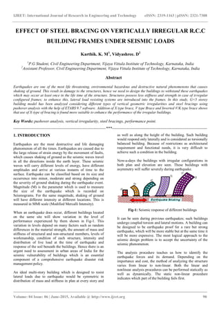
The elements begin to yield and deform in elastically as the
load and displacement increases. The resulting curve shows
the capacity of the building and demand from a specific
earthquake (or) intensity of ground shaking. This graph will
generate a point on the curve where capacity and demand
are equal and is called as „Performance point‟. It is an
estimate of actual displacement of building for the specified
ground motion. This performance point helps an engineer to
characterize the associated damage state for the structure
and compare it with the desired performance objective.
At last, the procedure gives the engineer a better
understanding of the seismic performance characteristics of
the building and results in more effective designs in new
buildings and where as cost effective retrofits strategy in an
existing building. The guidelines which recommends on
these topics are ATC-40[16]
and FEMA-356[17]
.
2. STEEL BRACINGS SYSTEM
Braced-frames virtually eliminate the columns and girder
bending factors and thus improve the efficiency of the pure
rigid frame actions. By the addition of truss members such
as diagonals (between the floor systems) this can be
achieved effectively. These diagonals carry the lateral loads
and transfers the axial loads to the columns, which is an
effective structural system.
2.1Types of Bracing Systems
There are mainly two types of bracing systems.
i. Concentric bracing system.
ii. Eccentric bracing system
i. Concentric bracing increases the lateral stiffness of the
frame which in turn increases the natural frequency and
also decreases the lateral storey drift. Further, the
bracing increases the axial compression in the columns
to which they are connected by decreasing the bending
moments and shear forces in the column.
ii. Eccentric bracing improves the energy dissipation
capacity and reduces the lateral stiffness of the system.
At the point of connection of eccentric bracings on the
beams, the vertical component of the bracing force due
to earthquake causes concentrated load.
3. MODELING AND ANALYSIS
In the present study reinforced concrete frame building of
G+ 5 storeys is considered. The plan layout and elevations
of bare frames are shown in the figures below. The different
configurations of buildings are modeled by considering only
mass of the infill. The storey height is kept uniform of 3m
for all building models. The building models are studied for
vertical geometric irregularity in seismic zone V of India.
Later on Steel bracings are provided on the outer periphery
of the models on all the four sides and analyzed. Types of
bracings considered for the study are X-type, V-type and K-
type bracing.
Table-1: Assumed data for the study
Sl
No.
Contents Description
1 Grade of Concrete M30
2
Young‟s modulus of
Concrete, E
27386.127 N/mm2
3 Density of Concrete 25 kN/m3
4 Poisson‟s ratio of Concrete 0.2
5 Grade of Steel Fe415
6 Young‟s modulus of Steel 20000 N/mm2
7 Density of Steel 76.81 kN/m3
8 Poisson‟s ratio of Steel 0.3
9 Slab thickness 0.15m
10 Size of Column
0.3m X 0.5 m
(upto roof from 5th
floor)
0.3m X 0.8 m
(upto 5th from base)
11 Size of Beam
0.3m X 0.45 m
(upto roof from 5th
floor)
0.3m X 0.6 m (upto
5th floor from base)
12 Bracing section ISMB350
13 Roof and Floor finish 1 kN/mm2
14 Live load on Roof 2 kN/mm2
15 Live load on Floor 3 kN/mm2
16 Wall load 12 kN/mm2
Model M-1- Building is modeled as bare frame, however the
mass of the walls are included. The plan of the
building is symmetrical in shape and
consisting of 5X5 bays (Fig-4).
Model M-2- Building is modeled as bare frame. The
Vertical configuration of the structure and
lateral force resisting system in top storey](data:image/gif;base64,R0lGODlhAQABAIAAAAAAAP///yH5BAEAAAAALAAAAAABAAEAAAIBRAA7)
Recommended
Recommended
More Related Content
What's hot
What's hot (20)
Viewers also liked
Viewers also liked (17)
Similar to Effect of steel bracing on vertically irregular r.c.c building frames under seismic loads
Similar to Effect of steel bracing on vertically irregular r.c.c building frames under seismic loads (20)
More from eSAT Journals
More from eSAT Journals (20)
Recently uploaded
Recently uploaded (20)
Effect of steel bracing on vertically irregular r.c.c building frames under seismic loads
- 1. IJRET: International Journal of Research in Engineering and Technology eISSN: 2319-1163 | pISSN: 2321-7308 _______________________________________________________________________________________ Volume: 04 Issue: 06 | June-2015, Available @ http://www.ijret.org 90 EFFECT OF STEEL BRACING ON VERTICALLY IRREGULAR R.C.C BUILDING FRAMES UNDER SEISMIC LOADS Karthik. K. M1 , Vidyashree. D2 1 P.G Student, Civil Engineering Department, Vijaya Vittala Institute of Technology, Karnataka, India 2 Assistant Professor, Civil Engineering Department, Vijaya Vittala Institute of Technology, Karnataka, India Abstract Earthquakes are one of the most life threatening, environmental hazardous and destructive natural phenomenons that causes shaking of ground. This result in damage to the structures, hence we need to design the buildings to withstand these earthquakes which may occur at least once in the life time of the structure. Structures possess less stiffness and strength in case of irregular configured frames; to enhance this, lateral load resisting systems are introduced into the frames. In this study, G+5 storey building model has been analyzed considering different types of vertical geometric irregularities and steel bracings using pushover analysis with the help of ETABS 9.7 software. Addition of X type brace, V type Brace and Inverted V/K type brace shows that use of X-type of bracing is found more suitable to enhance the performance of the irregular buildings. Key Words: pushover analysis, vertical irregularity, steel bracings, performance point. --------------------------------------------------------------------***---------------------------------------------------------------------- 1. INTRODUCTION Earthquakes are the most destructive and life damaging phenomenon of all the times. Earthquakes are caused due to the large release of strain energy by the movement of faults, which causes shaking of ground as the seismic waves travel in all the directions inside the earth layer. These seismic waves will carry different levels of energy, have different amplitudes and arrive at various instants of time to the surface. Earthquake can be classified based on its size and occurrence into minor, moderate and strong depending on the severity of ground shaking during the earthquake event. Magnitude (M) is the parameter which is used to measure the size of the earthquake which is recorded on Seismograms. For the same magnitude, shaking of ground will have different intensity at different locations. This is measured in MMI scale (Modified Mercalli Intensity). When an earthquake does occur, different buildings located on the same site will show variation in the level of performance experienced by them shown in Fig-1. This variation in levels depend on many factors such as random differences in the material strength, the amount of mass and stiffness of structural and non-structural members, levels of workmanship, condition of each structure, intensity and distribution of live load at the time of earthquake and response of the soil beneath the buildings. Hence there is an urgent need to assessment in urban areas of India for the seismic vulnerability of buildings which is an essential component of a comprehensive earthquake disaster risk management policy. An ideal multi-story building which is designed to resist lateral loads due to earthquake would be symmetric in distribution of mass and stiffness in plan at every story and as well as along the height of the building. Such building would respond only laterally and is considered as torsionally balanced building. Because of restrictions as architectural requirement and functional needs, it is very difficult to achieve such a condition in the building. Now-a-days the buildings with irregular configurations in both plan and elevation are seen. These buildings with asymmetry will suffer severely during earthquake. Fig-1: Seismic response of different buildings It can be seen during previous earthquakes; such buildings undergo coupled torsion and lateral motions. A building can be designed to be earthquake proof for a rare but strong earthquake, which will be more stable but at the same time it will be more expensive. The most logical approach to the seismic design problem is to accept the uncertainty of the seismic phenomenon. The analysis procedure teaches us how to identify the earthquake forces and its demand. Depending on the importance and cost, the method of analyzing the structure varies from linear to non-linear. Both the linear and nonlinear analysis procedures can be performed statically as well as dynamically. The static non-linear procedure indicates which part of the building fails first.
- 2. IJRET: International Journal of Research in Engineering and Technology eISSN: 2319-1163 | pISSN: 2321-7308 _______________________________________________________________________________________ Volume: 04 Issue: 06 | June-2015, Available @ http://www.ijret.org 91 The elements begin to yield and deform in elastically as the load and displacement increases. The resulting curve shows the capacity of the building and demand from a specific earthquake (or) intensity of ground shaking. This graph will generate a point on the curve where capacity and demand are equal and is called as „Performance point‟. It is an estimate of actual displacement of building for the specified ground motion. This performance point helps an engineer to characterize the associated damage state for the structure and compare it with the desired performance objective. At last, the procedure gives the engineer a better understanding of the seismic performance characteristics of the building and results in more effective designs in new buildings and where as cost effective retrofits strategy in an existing building. The guidelines which recommends on these topics are ATC-40[16] and FEMA-356[17] . 2. STEEL BRACINGS SYSTEM Braced-frames virtually eliminate the columns and girder bending factors and thus improve the efficiency of the pure rigid frame actions. By the addition of truss members such as diagonals (between the floor systems) this can be achieved effectively. These diagonals carry the lateral loads and transfers the axial loads to the columns, which is an effective structural system. 2.1Types of Bracing Systems There are mainly two types of bracing systems. i. Concentric bracing system. ii. Eccentric bracing system i. Concentric bracing increases the lateral stiffness of the frame which in turn increases the natural frequency and also decreases the lateral storey drift. Further, the bracing increases the axial compression in the columns to which they are connected by decreasing the bending moments and shear forces in the column. ii. Eccentric bracing improves the energy dissipation capacity and reduces the lateral stiffness of the system. At the point of connection of eccentric bracings on the beams, the vertical component of the bracing force due to earthquake causes concentrated load. 3. MODELING AND ANALYSIS In the present study reinforced concrete frame building of G+ 5 storeys is considered. The plan layout and elevations of bare frames are shown in the figures below. The different configurations of buildings are modeled by considering only mass of the infill. The storey height is kept uniform of 3m for all building models. The building models are studied for vertical geometric irregularity in seismic zone V of India. Later on Steel bracings are provided on the outer periphery of the models on all the four sides and analyzed. Types of bracings considered for the study are X-type, V-type and K- type bracing. Table-1: Assumed data for the study Sl No. Contents Description 1 Grade of Concrete M30 2 Young‟s modulus of Concrete, E 27386.127 N/mm2 3 Density of Concrete 25 kN/m3 4 Poisson‟s ratio of Concrete 0.2 5 Grade of Steel Fe415 6 Young‟s modulus of Steel 20000 N/mm2 7 Density of Steel 76.81 kN/m3 8 Poisson‟s ratio of Steel 0.3 9 Slab thickness 0.15m 10 Size of Column 0.3m X 0.5 m (upto roof from 5th floor) 0.3m X 0.8 m (upto 5th from base) 11 Size of Beam 0.3m X 0.45 m (upto roof from 5th floor) 0.3m X 0.6 m (upto 5th floor from base) 12 Bracing section ISMB350 13 Roof and Floor finish 1 kN/mm2 14 Live load on Roof 2 kN/mm2 15 Live load on Floor 3 kN/mm2 16 Wall load 12 kN/mm2 Model M-1- Building is modeled as bare frame, however the mass of the walls are included. The plan of the building is symmetrical in shape and consisting of 5X5 bays (Fig-4). Model M-2- Building is modeled as bare frame. The Vertical configuration of the structure and lateral force resisting system in top storey
- 3. IJRET: International Journal of Research in Engineering and Technology eISSN: 2319-1163 | pISSN: 2321-7308 _______________________________________________________________________________________ Volume: 04 Issue: 06 | June-2015, Available @ http://www.ijret.org 92 consist an offset of 60% in X direction only on one side (Fig-5). Model M-3- Building is modeled as bare frame. The Vertical configuration of a structure and lateral force resisting system in top story consist an offset of 40% in X direction on each side (Fig- 6). Model M-4- Building is modeled as bare frame. The Vertical configuration of a structure and lateral force resisting system in top story consist an offset of 20% in X direction on each side (Fig- 7). Model M-5- Building is modeled as bare frame. The Vertical configuration of a structure and lateral force resisting system in top story consist an offset of 16.66% in X direction on each side (Fig-8). Model M-6- Building is modeled as bare frame. The Vertical configuration of a structure and lateral force resisting system in top story consist an offset of 1.5 times lesser than the width of the base of the building in X direction only on one side (Fig-9). Fig-2: Common Plan for all the Models Fig-3: 3D view of Model M-1 Fig-4: Elevation of Model M-1 Fig-5: Elevation of Model M-2 Fig-6: Elevation of Model M-3 Fig-7: Elevation of Model M-4 Fig-8: Elevation of Model M-5
- 4. IJRET: International Journal of Research in Engineering and Technology eISSN: 2319-1163 | pISSN: 2321-7308 _______________________________________________________________________________________ Volume: 04 Issue: 06 | June-2015, Available @ http://www.ijret.org 93 Fig-9: Elevation of Model M-6 The analysis is carried out for the bare frames as well as for the braced frames by considering X type bracing, V type bracing and Inverted V/K bracing for the same model configurations described above. 4. RESULTS AND DISCUSSION G+5 storey building is analyzed for bare frame models and steel braced frame models for obtaining the following results. Later on the results of bare frame models are compared with braced frame models in terms of lateral displacement, storey drift, base shear and performance point. 4.1 Linear analysis 4.1.1 Lateral Displacement It is clear that the addition of bracings to the bare frames and irregular configured buildings will reduce the lateral displacement to a greater extent. Table-2: Comparison results of Lateral displacement (mm) for bare frame and braced frame models Chart-1: Comparison graph of Lateral Displacement for bare frame and braced frame models The above graph shows that the addition of X type bracing will reduce maximum lateral displacement in the bare frame models. Maximum displacement is seen in Model-5. The reduction varies from 80.3% to 78.1% by the use of X type bracing, 77% to 74.81% by the use of V type bracing and 77.73% to 75.91% by using K type bracing. We can see there is a reduction of 80.3% in the Model-1 by using X type steel bracing. 4.1.2 Storey drift Storey drift of the models are also reduced by the addition of steel bracings. For comparison maximum storey drift is considered. Table-3: Comparison results of Storey drift for bare frame and braced frame models Model No. Model M6 Model M6-X Model M6-V Model M6-K Model M-1 0.001937 0.000277 0.000323 0.00031 Model M-2 0.001836 0.000300 0.000348 0.000334 Model M-3 0.001472 0.000242 0.000282 0.000272 Model M-4 0.002074 0.000358 0.000413 0.000396 Model M-5 0.003178 0.000395 0.000456 0.000427 Model M-6 0.002532 0.000463 0.000535 0.000507 Chart-2: Comparison graph of Storey drift for bare frame and braced frame models Model No. Model M6 Model M6-X Model M6-V Model M6-K Model M-1 27.40 5.40 6.30 6.10 Model M-2 24.20 5.00 5.80 5.60 Model M-3 22.10 4.70 5.40 5.20 Model M-4 26.40 5.70 6.60 6.40 Model M-5 33.00 6.80 7.80 7.40 Model M-6 27.40 6.00 6.90 6.60
- 5. IJRET: International Journal of Research in Engineering and Technology eISSN: 2319-1163 | pISSN: 2321-7308 _______________________________________________________________________________________ Volume: 04 Issue: 06 | June-2015, Available @ http://www.ijret.org 94 The above graph shows that the addition of X type bracing will reduce maximum Storey drift in the bare frame models. Maximum storey drift is seen in Model-5. The reduction varies from 87.57% to 81.71% by the use of X type bracing, 85.65% to 78.87% by the use of V type bracing and 86.56% to 79.97% by using K type bracing. We can see there is a reduction of 87.57% in the Model-5 by using X type steel bracing. 4.1.3 Base Shear There is a slight increase in the base shear of the buildings considered by the addition of bracings. Table-4: Comparison results of Base shear (kN) for bare frame and braced frame models Model No. Model M6 Model M6-X Model M6-V Model M6-K Model M-1 4339.42 4397.78 4378.51 4378.51 Model M-2 3662.03 3714.03 3696.86 3696.86 Model M-3 3732.30 3784.25 3767.08 3767.08 Model M-4 3291.30 3341.14 3324.67 3324.67 Model M-5 2963.36 3011.48 2995.82 2995.82 Model M-6 3217.12 3266.26 3250.13 3250.13 Chart-3: Comparison graph of Base shear for bare frame and braced frame models 4.2 Performance Point Performance point is an estimate of the actual displacement and base shear of the building for the specified ground motion. Addition of bracings to the bare frame shows a huge increase in the performance point. Table-5: Comparison results of Performance point (kN) for bare frame and braced frame models Model No. Model M6 Model M6-X Model M6-V Model M6-K Model M-1 10585.86 35516.17 33580.93 34382.76 Model M-2 9550.87 29485.13 29238.73 29222.47 Model M-3 9919.22 31252.45 31030.3 31098.73 Model M-4 8197.05 23665.88 23354.24 23555.87 Model M-5 8280.85 22504.27 20596.37 21526.46 Model M-6 8217.73 22283.3 22205.44 22178.96 Chart-4: Comparison graph of Performance point (kN) for bare frame and braced frame models The above graph shows that the addition of X type bracing will increase maximum performance point in the bare frame models. Minimum performance point is seen in Model-4. The increase varies from 235.50% to 171.16% by the use of X type bracing, 217.22% to 148.72% by the use of V type bracing and 224.79% to 159.95% by using K type bracing. We can see there is an increase of 235.50% in the Model-1 by using X type steel bracing. 5. CONCLUSIONS The analysis of G+5 storey model for regular and irregular configuration with the addition of steel bracings concludes the following. 1. Introduction of irregularities affects the performance of the building. 2. Lateral displacement and Storey drift increases as the amount of irregularity present in the building increases. 3. Base shear of irregular configured buildings will be less compared with the regular building. 4. Performance point of regular frame is found more than the irregular frame. 5. Addition of bracings to the bare frames shows reduction in lateral displacement and storey drift.
- 6. IJRET: International Journal of Research in Engineering and Technology eISSN: 2319-1163 | pISSN: 2321-7308 _______________________________________________________________________________________ Volume: 04 Issue: 06 | June-2015, Available @ http://www.ijret.org 95 6. Base shear of the bare frame is also increased in the presence of steel bracings. 7. There is large increase in the Performance point of bare frames when the bracings are added to it. 8. Use of X type of bracing is found more suitable among all the bracings considered in this study. From the above conclusions it is clear that the use of irregular configuration will cause greater damage to the structure during earthquakes. Hence addition of steel bracings improves its lateral load carrying capacity REFERENCES [1] Z.A. Siddiqi, Rashid Hameed, Usman Akmal, “Comparison of Different Bracing Systems for Tall Buildings”, Pak. J. Engg. & Appl. Sci. Vol. 14, Jan., 2014 (P. 17-26). [2] Spoorthi S K, Dr. Jagadish Kori G, “Effect of Soft Storey on Tall Buildings At Various storeis by Pushover Analysis”, International Journal Of Engineering Research-Online Vol.2. Issue.3. 2014 ISSN: 2321-7758. [3] M.D. Kevadkar, P.B. Kodag, “Lateral Load Analysis of R.C.C. Building”, International Journal of Modern Engineering Research (IJMER) Vol.3, Issue.3, May- June. 2013 Pp-1428-1434 ISSN: 2249-6645. [4] D. B. Karwar, Dr. R. S. Londhe, “Performance of RC Framed Structure by Using Pushover Analysis”, International Journal Of Emerging Technology And Advanced Engineering (ISSN 2250-2459, ISO 9001:2008 Certified Journal, Volume 4, Issue 6, June 2014). [5] Rahiman G. Khan, Prof. M. R. Vyawahare, “Push Over Analysis of Tall Building with Soft Stories at Different Levels”, International Journal of Engineering Research and Applications (IJERA) ISSN: 2248-9622 Vol. 3, Issue 4, Jul-Aug 2013, Pp.176-185. [6] Akshay V. Raut, Prof. RVRK Prasad, “Pushover Analysis of G+3 Reinforced Concrete Building with Soft Storey”, IOSR Journal Of Mechanical And Civil Engineering (IOSR-JMCE) E-ISSN: 2278-1684,P- ISSN: 2320-334x, Volume 11, Issue 4 Ver. I (Jul- Aug. 2014), Pp 25-29. [7] Mohommed Anwaruddin Md. Akberuddin, Mohd. Zameeruddin Mohd. Saleemuddin, “Pushover Analysis of Medium Rise Multi-Story RCC Frame With And Without Vertical Irregularity”, M A M Akberuddin Et Al. Int. Journal Of Engineering Research And Applications ,Vol. 3, Issue 5, Sep-Oct 2013, Pp.540- 546. [8] C.M. Ravi Kumar, K.S. Babu Narayan, M.H. Prashanth, H.B Manjunatha and D. Venkat Reddy, “Seismic Performance Evaluation of RC Buildings With Vertical Irregularity”, ISET Golden Jubilee Symposium Indian Society Of Earthquake Technology Department Of Earthquake Engineering Building IIT Roorkee, Roorkee, October 20-21, 2012, Paper No. E012. [9] Braz-César M. T., Barros R. C., “Seismic Performance of Metallic Braced Frames by Pushover Analysis”, Compdyn 2009 Eccomas Thematic Conference On Computational Methods In Structural Dynamics And Earthquake Engineering M. Papadrakakis, N.D. Lagaros, M. Fragiadakis (Eds.) Rhodes, Greece, 22–24 June 2009. [10] Madhusudan G. Kalibhat, Arun Kumar Y.M, Kiran Kamath, Prasad .S.K, Shrinath Shet, “Seismic Performance of R.C. Frames with Vertical Stiffness Irregularity from Pushover Analysis”, IOSR Journal of Mechanical and Civil Engineering (IOSR-JMCE) E- ISSN: 2278-1684, P-ISSN: 2320-334x Pp 61-66. [11] Shaikh Abdul Aijaj Abdul Rahman, Girish Deshmukh, “Seismic Response of Vertically Irregular RC Frame With Stiffness Irregularity at Fourth Floor”, International Journal Of Emerging Technology And Advanced Engineering Website: Www.Ijetae.Com (ISSN 2250-2459,ISO 9001:2008 Certified Journal, Volume 3, Issue 8, August 2013). [12] Viswanath K.G, Prakash K.B., Anant Desai,“Seismic Analysis of Steel Braced ReinforcedConcrete Frames”,I nternational Journal Of Civil And Structural Engineerin g Volume 1, No 1, 2010 ISSN 0976 – 4399. [13] Suchita Hirde and Ganga Tepugade, “Seismic Performance of Multistorey Building with Soft Storey at Different Level with R.C Shear Wall”, International Journal of Current Engineering and Technology E-ISSN 2277 – 4106, P-ISSN 2347 – 5161. [14] Shailendra Kumar Damodar Dubey and Sunil Y Kute, “ Experimental investigation on the ultimate strength of partially infilled and steel braced reinforced concrete frames”, International Journal Of Advanced Structural Engineering 2013, 5: 15 [15] Abhilash R, Biju V., Rahul Leslie, “Effect of Lateral Load Patterns in Pushover Analysis”, 10th National Conference on Technological Trends (NCTT09) 6-7 Nov 2009 [16] ATC 40 “Seismic evaluation and retrofit of concrete buildings” Volume 1, California seismic safety commission, California. [17] FEMA 356 “Pre Standard and Commentary for the Seismic Rehabilitation of the Buildings”, Federal Emergency Management Agency, Washington D.C. [18] S.K. Duggal, “Earthquake resistant design of structures”, Oxford university press, New Delhi. [19] IS 1893(PART I) 2002, “Criteria for earthquake resistant design of structures, Part 1 General provisions and buildings”, fifth revision, Bureau of Indian Standards, New Delhi, India. [20] Mohammed Idrees Khan, Mr.Khalid Nayaz Khan, “Seismic Analysis of Steel Frame With Bracings Using Pushover Analysis”, International Journal of Advanced Technology in Engineering and Science, Volume No.02, Issue No. 07, July 2014 ISSN (online): 2348 – 7550.
- 7. IJRET: International Journal of Research in Engineering and Technology eISSN: 2319-1163 | pISSN: 2321-7308 _______________________________________________________________________________________ Volume: 04 Issue: 06 | June-2015, Available @ http://www.ijret.org 96 BIOGRAPHIES Karthik. K. M, P.G Student, M.Tech- Structural Engineering, Civil Engineering Department, Vijaya Vittala Institute of Technology, Bengaluru, Karnataka, India. Completed Bachelor of Engineering in Civil Engineering from Nagarjuna College of Engineering and Technology, Devanahalli, Bengaluru, Karnataka, India. Vidyashree. D, Asst. Professor, Civil Engineering Department, Vijaya Vittala Institute of Technology, Bengaluru, Karnataka, India. Subjects handled: Structural Masonry, Earthquake Resist Structures, Design concepts of Substructures and Advanced Concrete Technology.