Dr. Warren Vaneman, a retired U.S. Navy Reserve Captain and professor at the Naval Postgraduate School, presented on model-based systems engineering (MBSE) highlighting its transition from document-based to model-based practices. The presentation discussed the complexities of modern systems and the necessity of utilizing modeling languages and ontologies to improve system design and analysis. Vaneman emphasized the importance of integrating MBSE tools within a framework to enhance collaboration and manage the intricacies of system engineering effectively.
Dr. Warren Vaneman
CAPT,USNR (Ret.)
Professor of Practice
Email: wvaneman@nps.edu
Systems Engineering Department
Naval Postgraduate School
Presented to
SPEC Innovations Webinar
August 30th, 2018
2.
2
▼ Military Experience
Retired U.S. Navy Reserve Captain
Qualified Surface Warfare, Information Dominance Warfare & Space Cadre Officer
MAJOR CAMPAIGNS & OPERATIONS: Desert Shield/Desert Storm, Enduring Freedom-Afghanistan, Operation Burnt Frost
2
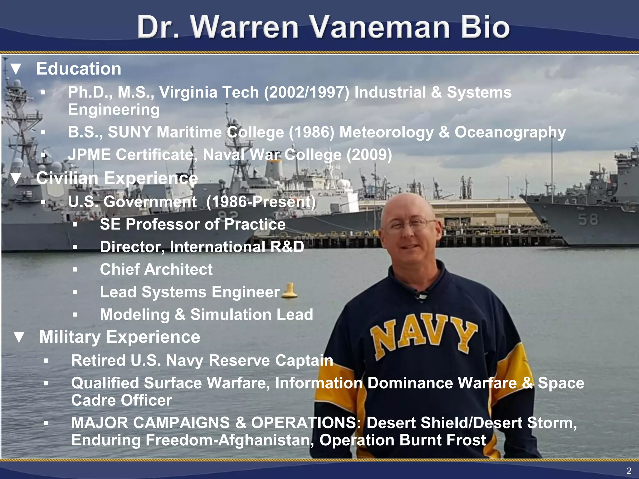
▼ Education
Ph.D., M.S., Virginia Tech (2002/1997) Industrial & Systems
Engineering
B.S., SUNY Maritime College (1986) Meteorology & Oceanography
JPME Certificate, Naval War College (2009)
▼ Civilian Experience
U.S. Government (1986-Present)
SE Professor of Practice
Director, International R&D
Chief Architect
Lead Systems Engineer
Modeling & Simulation Lead
▼ Military Experience
Retired U.S. Navy Reserve Captain
Qualified Surface Warfare, Information Dominance Warfare & Space
Cadre Officer
MAJOR CAMPAIGNS & OPERATIONS: Desert Shield/Desert Storm,
Enduring Freedom-Afghanistan, Operation Burnt Frost
3.
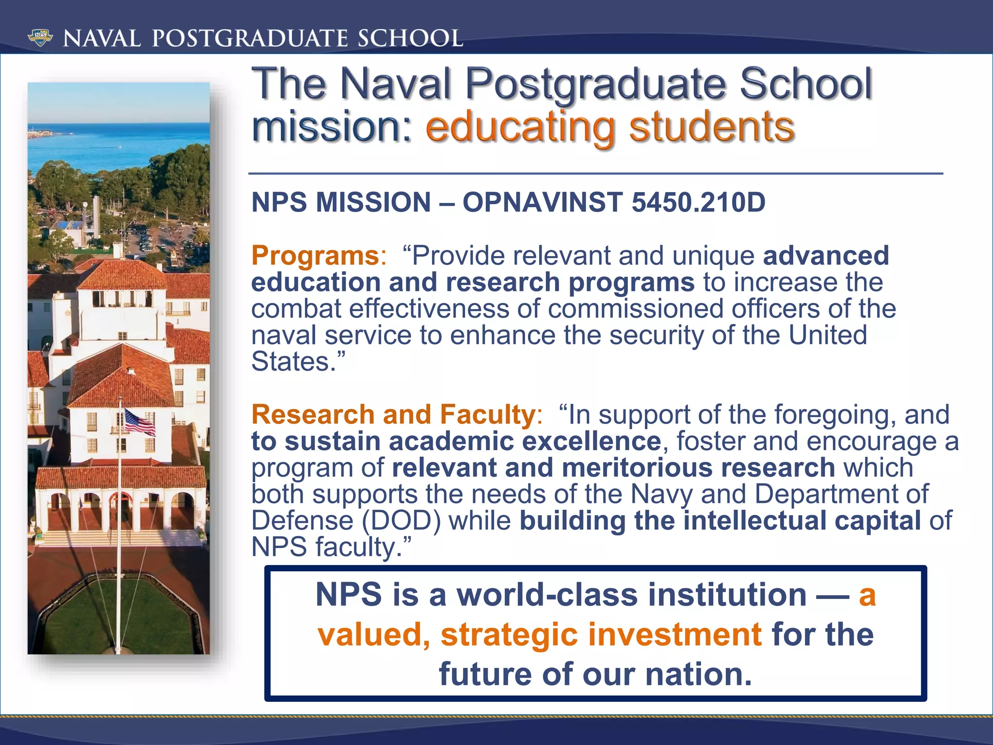
NPS MISSION –OPNAVINST 5450.210D
Programs: “Provide relevant and unique advanced
education and research programs to increase the
combat effectiveness of commissioned officers of the
naval service to enhance the security of the United
States.”
Research and Faculty: “In support of the foregoing, and
to sustain academic excellence, foster and encourage a
program of relevant and meritorious research which
both supports the needs of the Navy and Department of
Defense (DOD) while building the intellectual capital of
NPS faculty.”
NPS is a world-class institution — a
valued, strategic investment for the
future of our nation.
5.
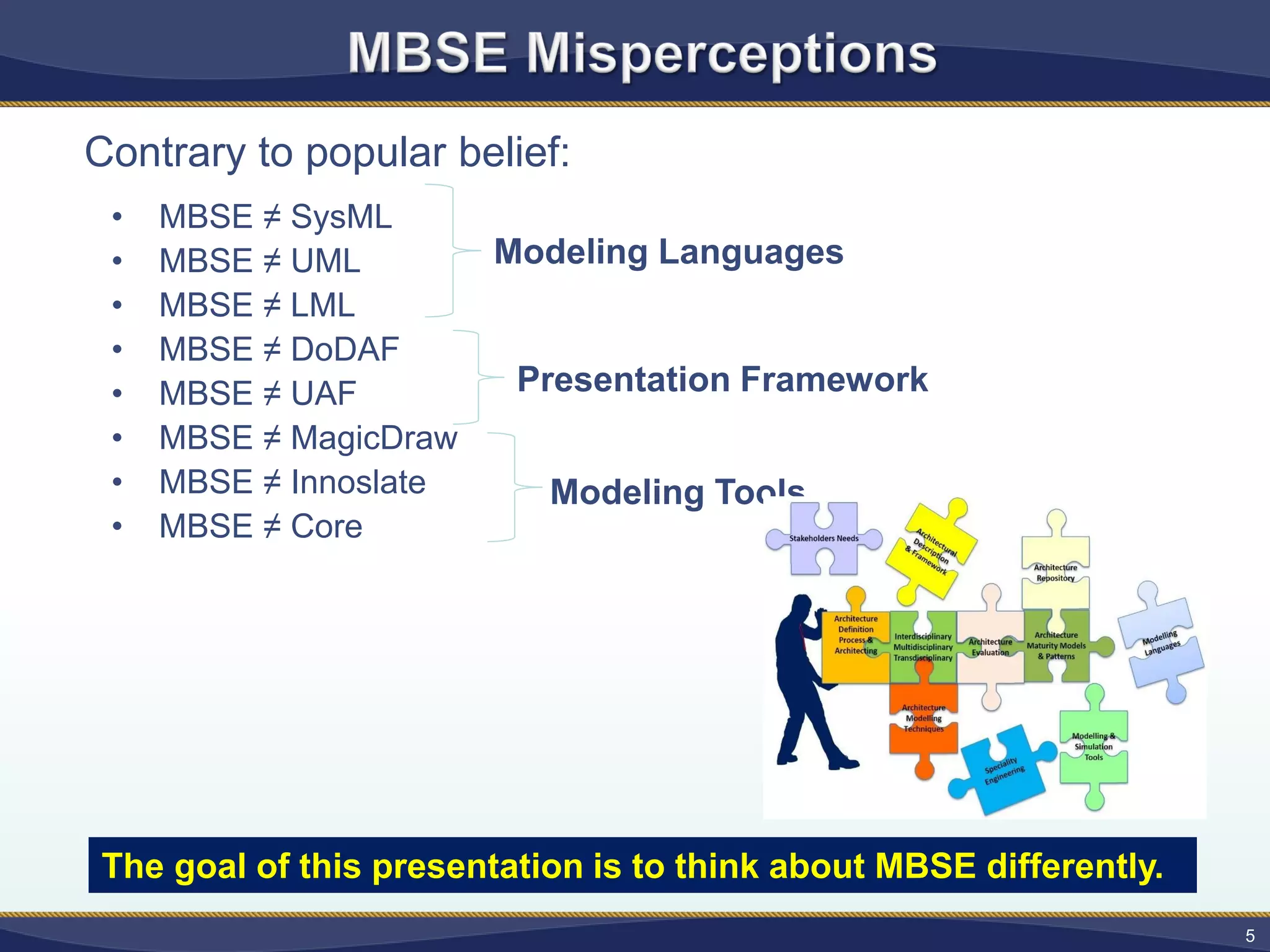
Contrary to popularbelief:
• MBSE ≠ SysML
• MBSE ≠ UML
• MBSE ≠ LML
• MBSE ≠ DoDAF
• MBSE ≠ UAF
• MBSE ≠ MagicDraw
• MBSE ≠ Innoslate
• MBSE ≠ Core
Modeling Languages
Presentation Framework
Modeling Tools
5
The goal of this presentation is to think about MBSE differently.
6.
6
• Advances intechnology have
led to larger, more complex
systems, which implies:
– A need for a clear concise way
to express the system design
(clear, logically consistent
semantics).
– New tools to enable
collaboration across the entire
lifecycle.
– A need for larger, distributed
teams.
Complexity has been identified by many as a critical
problem facing system engineers.
Photo Credit: http://www.afternoonspecial.com
7.
7
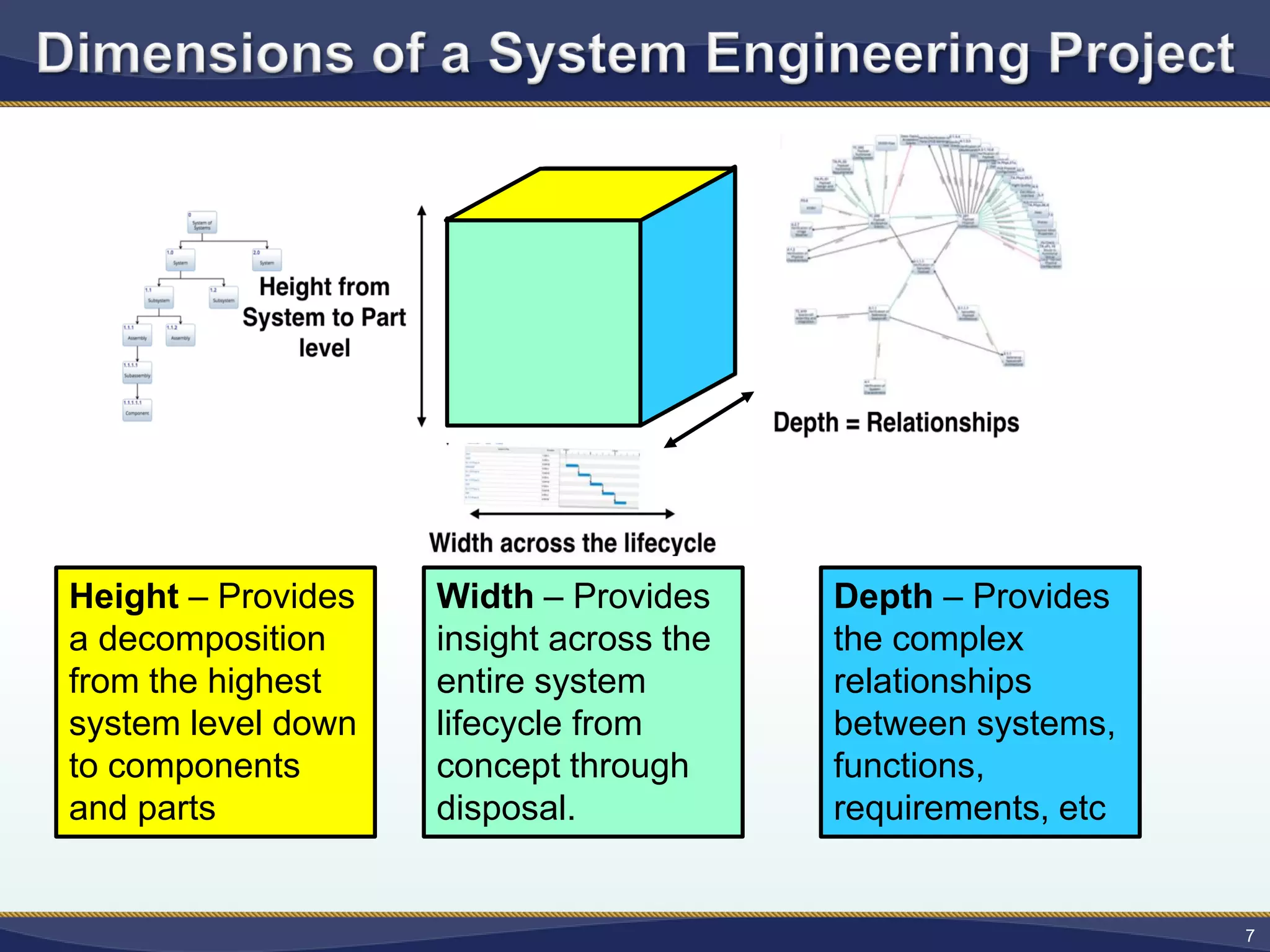
Width – Provides
insightacross the
entire system
lifecycle from
concept through
disposal.
Height – Provides
a decomposition
from the highest
system level down
to components
and parts
Depth – Provides
the complex
relationships
between systems,
functions,
requirements, etc
8.
8
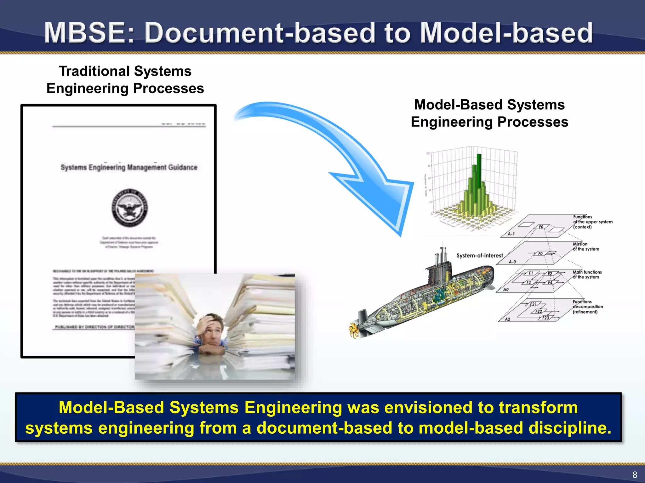
Model-Based Systems Engineeringwas envisioned to transform
systems engineering from a document-based to model-based discipline.
Traditional Systems
Engineering Processes
Model-Based Systems
Engineering Processes
9.
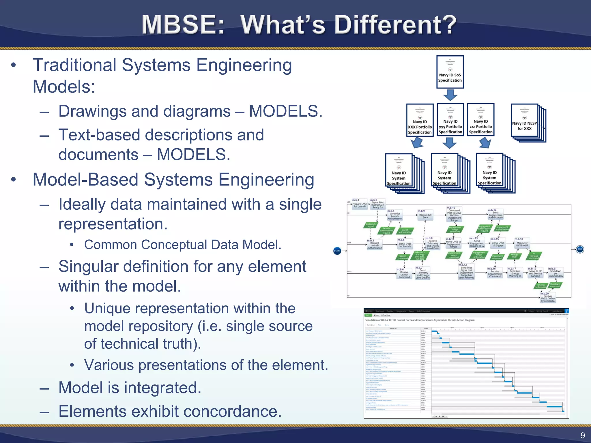
• Traditional SystemsEngineering
Models:
– Drawings and diagrams – MODELS.
– Text-based descriptions and
documents – MODELS.
• Model-Based Systems Engineering
– Ideally data maintained with a single
representation.
• Common Conceptual Data Model.
– Singular definition for any element
within the model.
• Unique representation within the
model repository (i.e. single source
of technical truth).
• Various presentations of the element.
– Model is integrated.
– Elements exhibit concordance.
9
10.
10
GRAPHIC DERIVED FROM:SySML
Fourm, http://www. sysmlforum.com
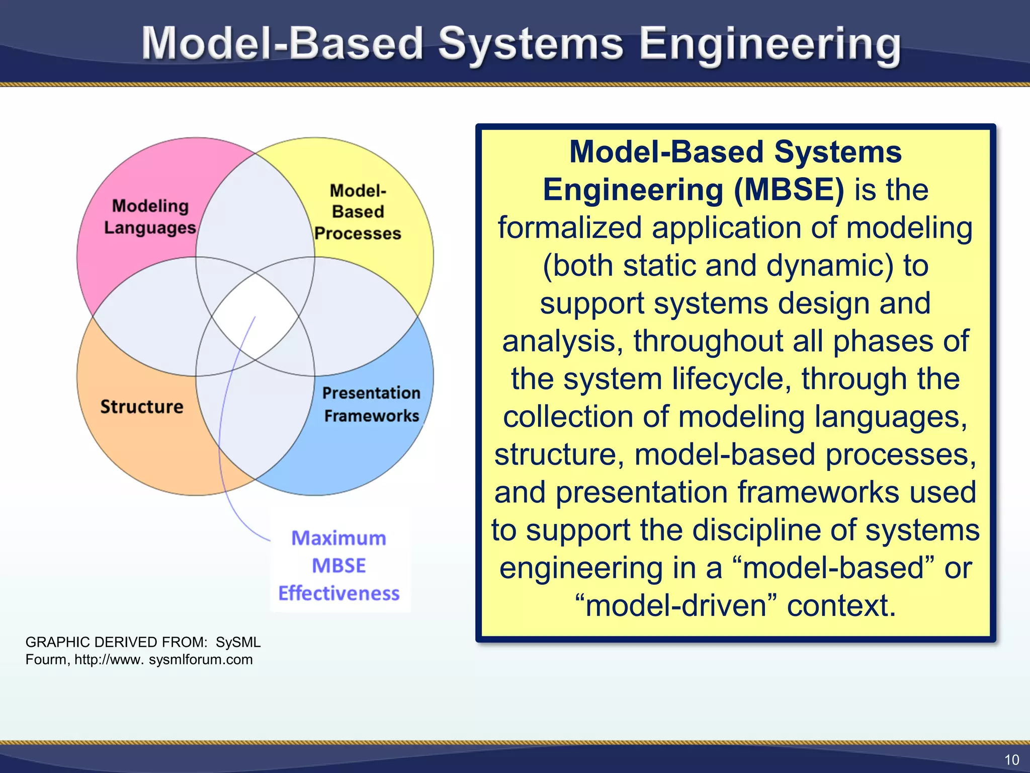
Model-Based Systems
Engineering (MBSE) is the
formalized application of modeling
(both static and dynamic) to
support systems design and
analysis, throughout all phases of
the system lifecycle, through the
collection of modeling languages,
structure, model-based processes,
and presentation frameworks used
to support the discipline of systems
engineering in a “model-based” or
“model-driven” context.
11.
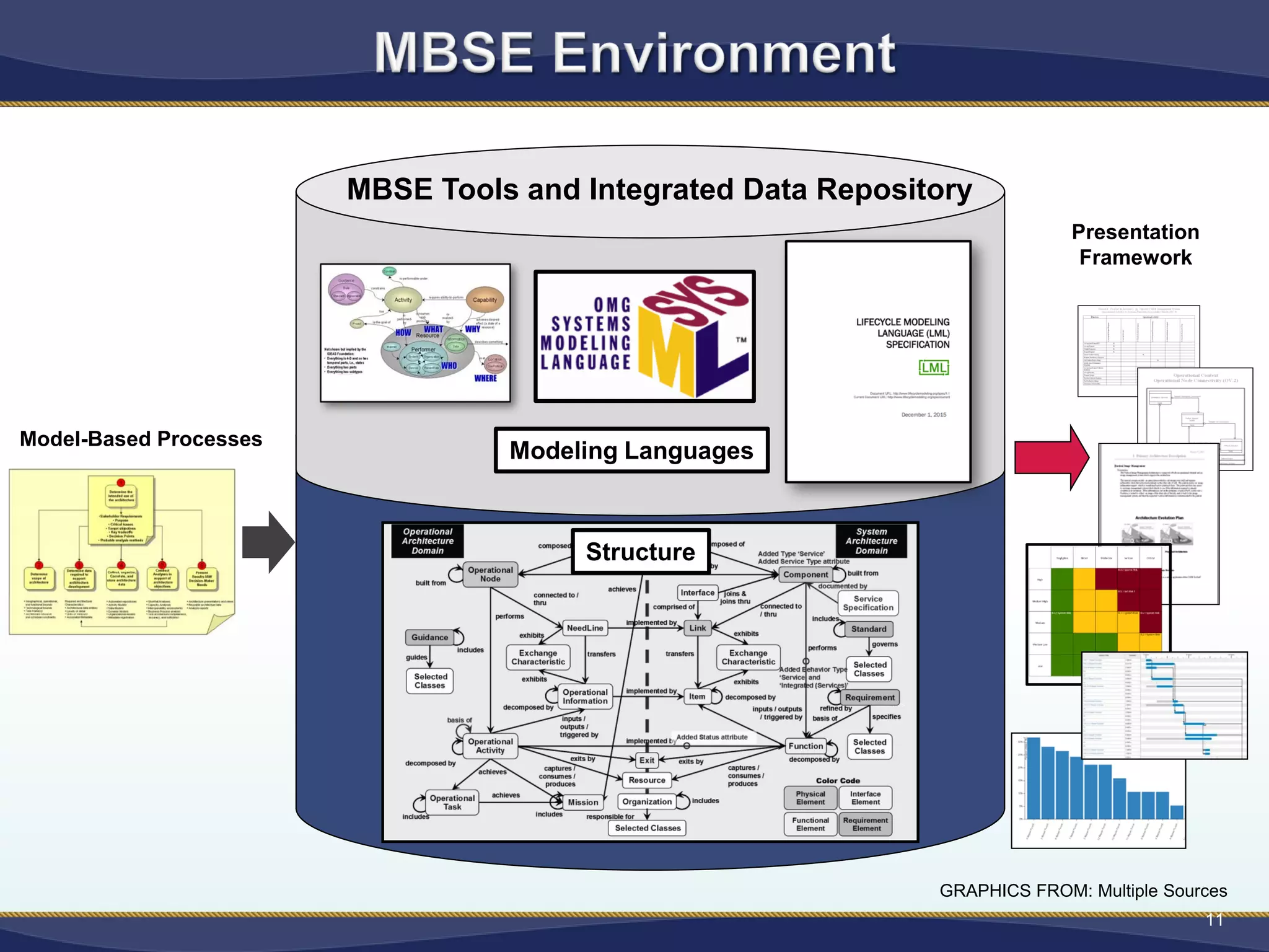
MBSE Tools andIntegrated Data Repository
11
Model-based
Processes
Structure
Presentation
Framework
Model-Based Processes
GRAPHICS FROM: Multiple Sources
Modeling Languages
12.
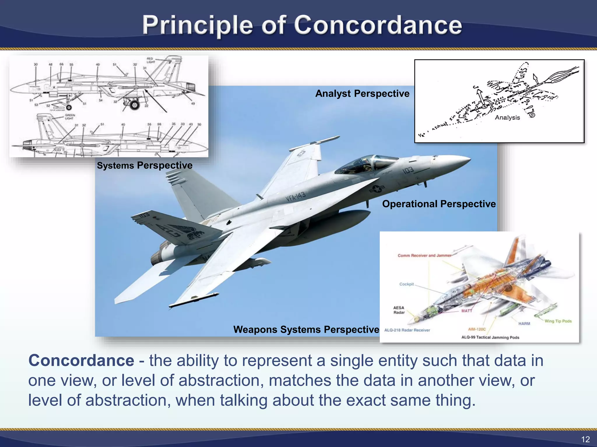
Concordance - theability to represent a single entity such that data in
one view, or level of abstraction, matches the data in another view, or
level of abstraction, when talking about the exact same thing.
Analyst Perspective
Weapons Systems Perspective
Operational Perspective
Systems Perspective
12
13.
• Structure definesthe relationships
between the system entities,
establishes concordance within the
model, and allows for the emergence
of system behaviors and performance
characterizations.
13
Systems consists not only of
“building blocks.”
Systems consists of “building blocks”
and the relationships between them that
form a complete and functional entity.
14.
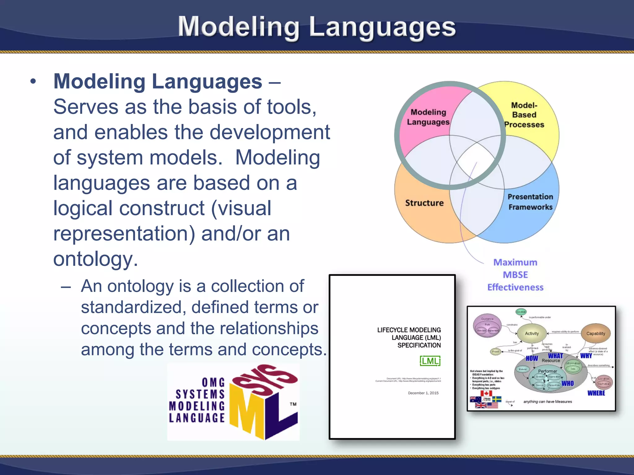
• Modeling Languages–
Serves as the basis of tools,
and enables the development
of system models. Modeling
languages are based on a
logical construct (visual
representation) and/or an
ontology.
– An ontology is a collection of
standardized, defined terms or
concepts and the relationships
among the terms and concepts.
15.
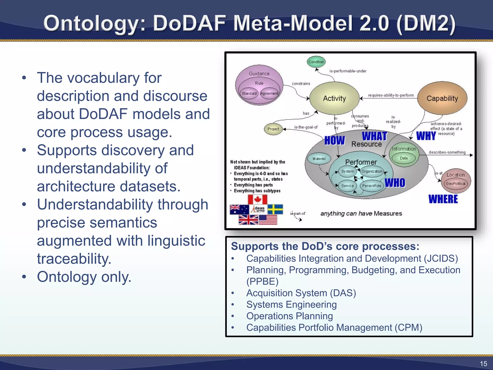
• The vocabularyfor
description and discourse
about DoDAF models and
core process usage.
• Supports discovery and
understandability of
architecture datasets.
• Understandability through
precise semantics
augmented with linguistic
traceability.
• Ontology only.
Supports the DoD’s core processes:
• Capabilities Integration and Development (JCIDS)
• Planning, Programming, Budgeting, and Execution
(PPBE)
• Acquisition System (DAS)
• Systems Engineering
• Operations Planning
• Capabilities Portfolio Management (CPM)
15
16.
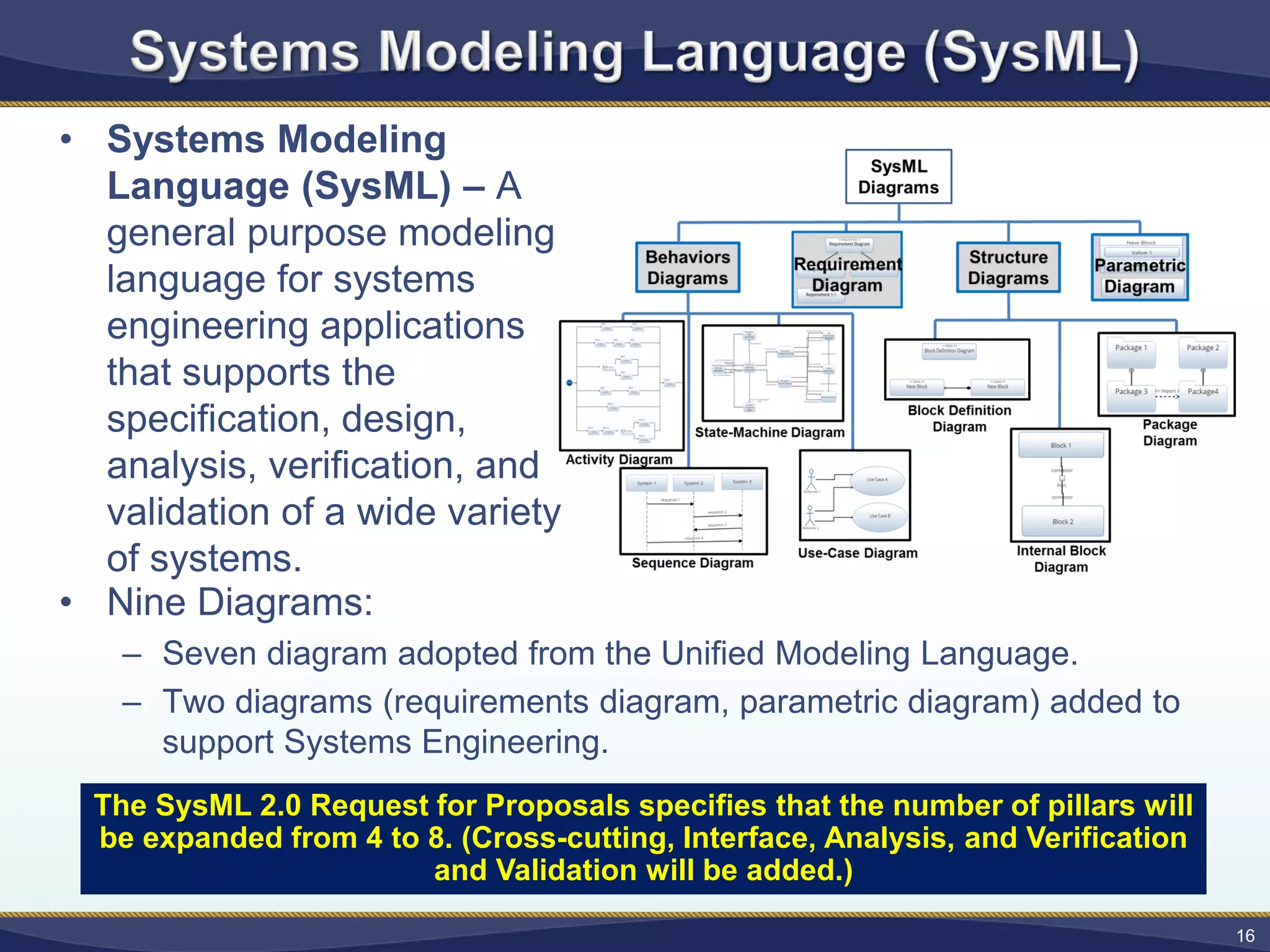
• Systems Modeling
Language(SysML) – A
general purpose modeling
language for systems
engineering applications
that supports the
specification, design,
analysis, verification, and
validation of a wide variety
of systems.
• Nine Diagrams:
– Seven diagram adopted from the Unified Modeling Language.
– Two diagrams (requirements diagram, parametric diagram) added to
support Systems Engineering.
16
The SysML 2.0 Request for Proposals specifies that the number of pillars will
be expanded from 4 to 8. (Cross-cutting, Interface, Analysis, and Verification
and Validation will be added.)
17.
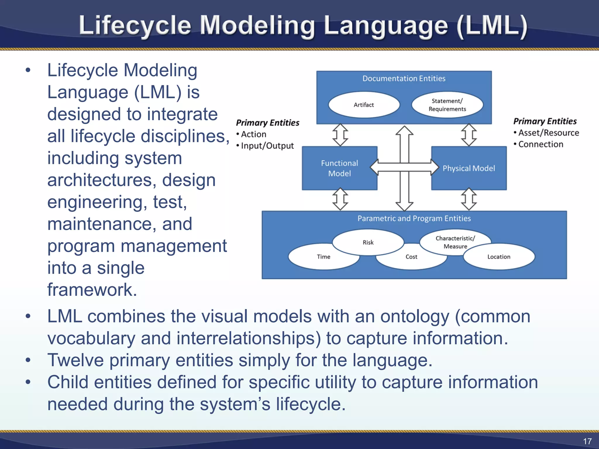
• Lifecycle Modeling
Language(LML) is
designed to integrate
all lifecycle disciplines,
including system
architectures, design
engineering, test,
maintenance, and
program management
into a single
framework.
• LML combines the visual models with an ontology (common
vocabulary and interrelationships) to capture information.
• Twelve primary entities simply for the language.
• Child entities defined for specific utility to capture information
needed during the system’s lifecycle.
17
18.
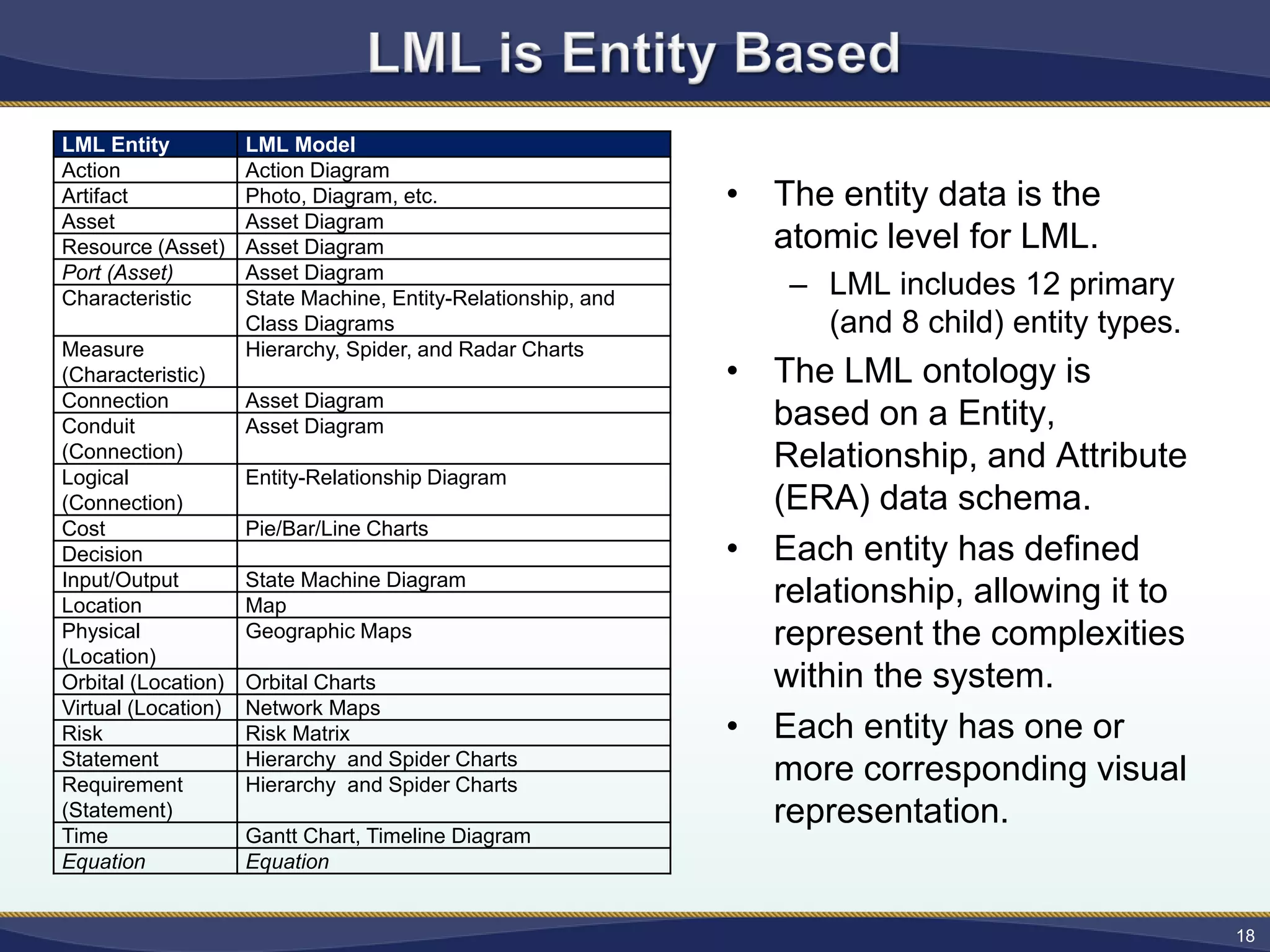
LML Entity LMLModel
Action Action Diagram
Artifact Photo, Diagram, etc.
Asset Asset Diagram
Resource (Asset) Asset Diagram
Port (Asset) Asset Diagram
Characteristic State Machine, Entity-Relationship, and
Class Diagrams
Measure
(Characteristic)
Hierarchy, Spider, and Radar Charts
Connection Asset Diagram
Conduit
(Connection)
Asset Diagram
Logical
(Connection)
Entity-Relationship Diagram
Cost Pie/Bar/Line Charts
Decision
Input/Output State Machine Diagram
Location Map
Physical
(Location)
Geographic Maps
Orbital (Location) Orbital Charts
Virtual (Location) Network Maps
Risk Risk Matrix
Statement Hierarchy and Spider Charts
Requirement
(Statement)
Hierarchy and Spider Charts
Time Gantt Chart, Timeline Diagram
Equation Equation
18
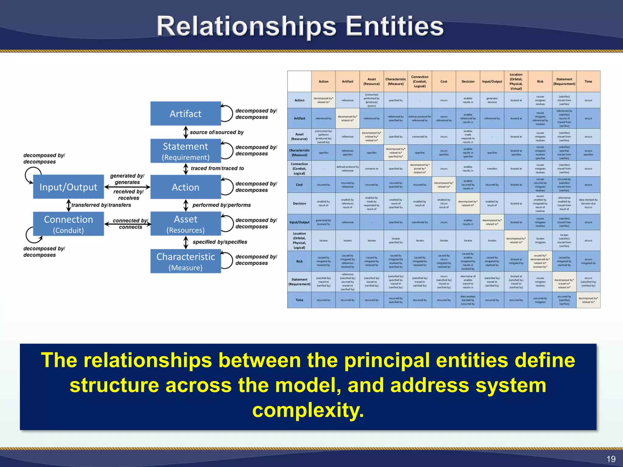
• The entity data is the
atomic level for LML.
– LML includes 12 primary
(and 8 child) entity types.
• The LML ontology is
based on a Entity,
Relationship, and Attribute
(ERA) data schema.
• Each entity has defined
relationship, allowing it to
represent the complexities
within the system.
• Each entity has one or
more corresponding visual
representation.
19.
19
The relationships betweenthe principal entities define
structure across the model, and address system
complexity.
20.
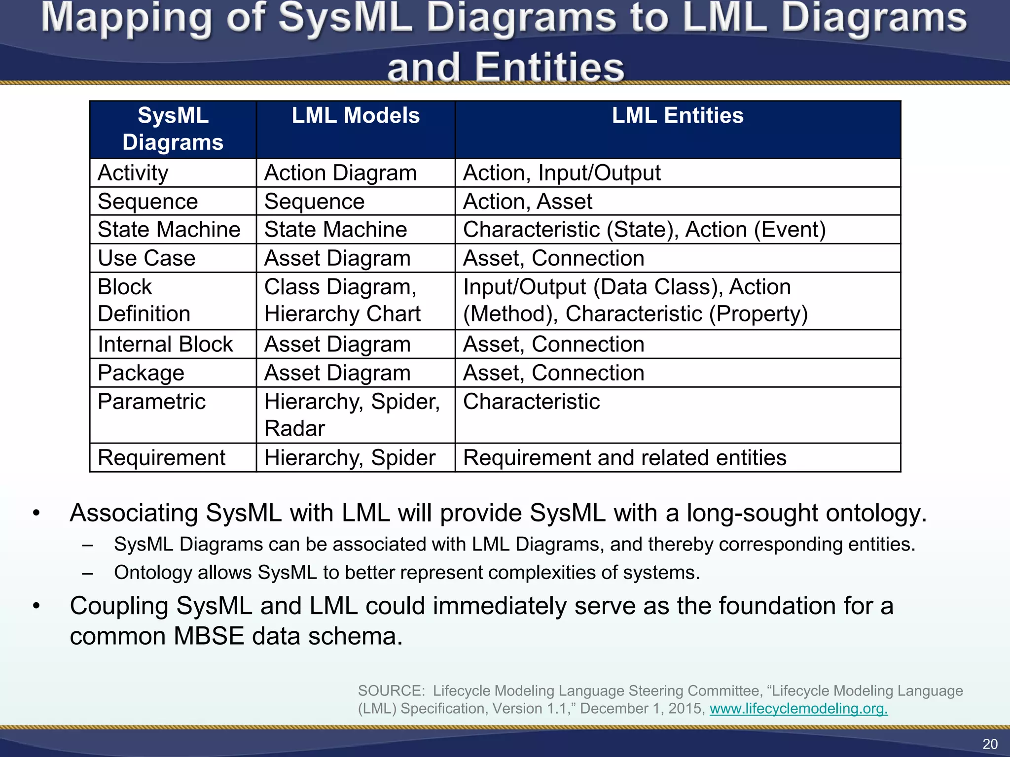
• Associating SysMLwith LML will provide SysML with a long-sought ontology.
– SysML Diagrams can be associated with LML Diagrams, and thereby corresponding entities.
– Ontology allows SysML to better represent complexities of systems.
• Coupling SysML and LML could immediately serve as the foundation for a
common MBSE data schema.
20
SOURCE: Lifecycle Modeling Language Steering Committee, “Lifecycle Modeling Language
(LML) Specification, Version 1.1,” December 1, 2015, www.lifecyclemodeling.org.
SysML
Diagrams
LML Models LML Entities
Activity Action Diagram Action, Input/Output
Sequence Sequence Action, Asset
State Machine State Machine Characteristic (State), Action (Event)
Use Case Asset Diagram Asset, Connection
Block
Definition
Class Diagram,
Hierarchy Chart
Input/Output (Data Class), Action
(Method), Characteristic (Property)
Internal Block Asset Diagram Asset, Connection
Package Asset Diagram Asset, Connection
Parametric Hierarchy, Spider,
Radar
Characteristic
Requirement Hierarchy, Spider Requirement and related entities
21.
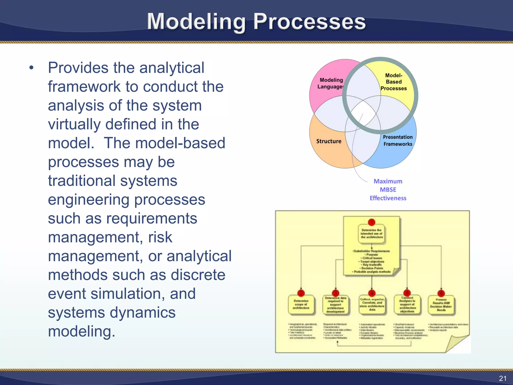
• Provides theanalytical
framework to conduct the
analysis of the system
virtually defined in the
model. The model-based
processes may be
traditional systems
engineering processes
such as requirements
management, risk
management, or analytical
methods such as discrete
event simulation, and
systems dynamics
modeling.
21
22.
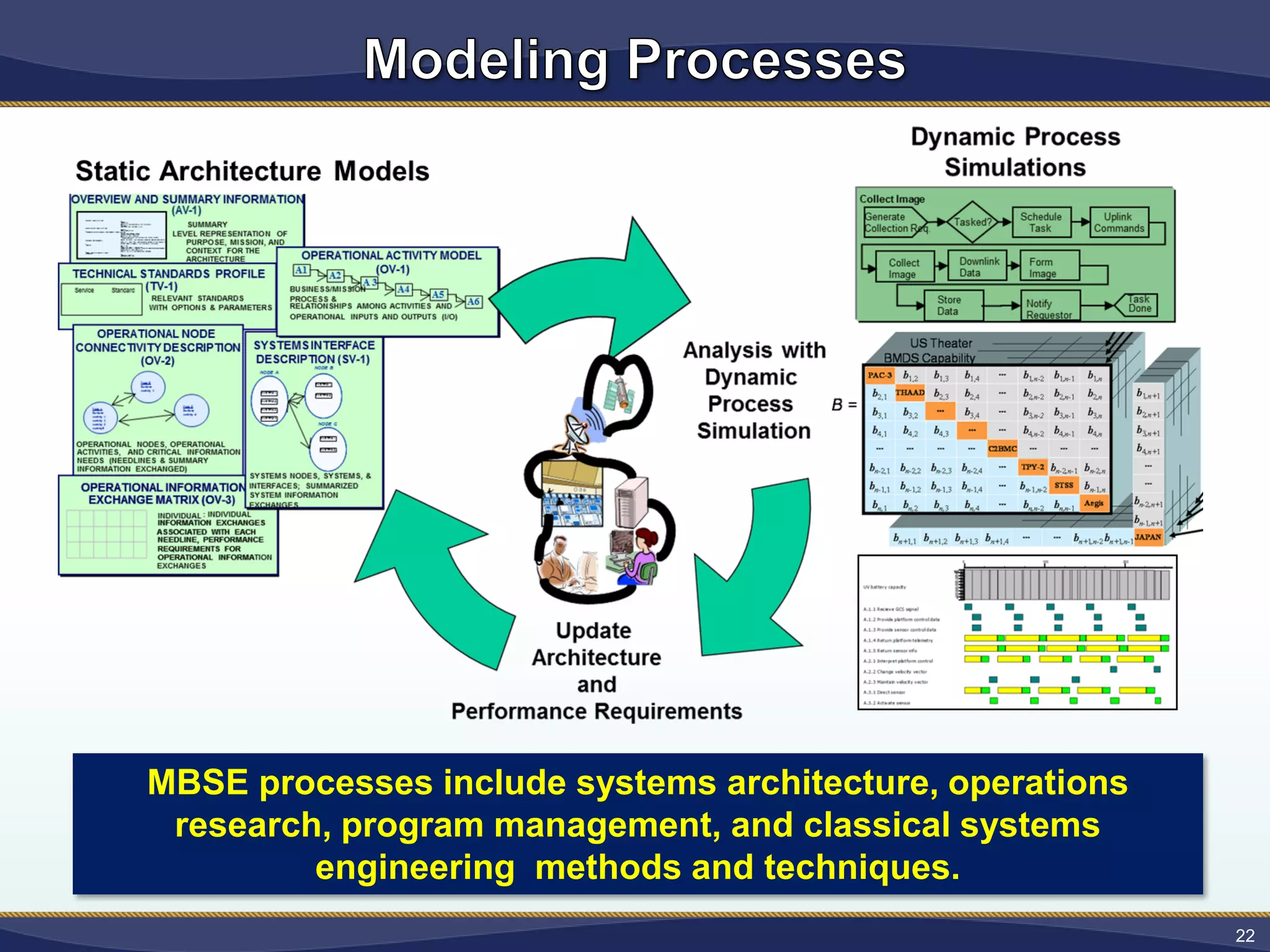
MBSE processes includesystems architecture, operations
research, program management, and classical systems
engineering methods and techniques.
22
23.
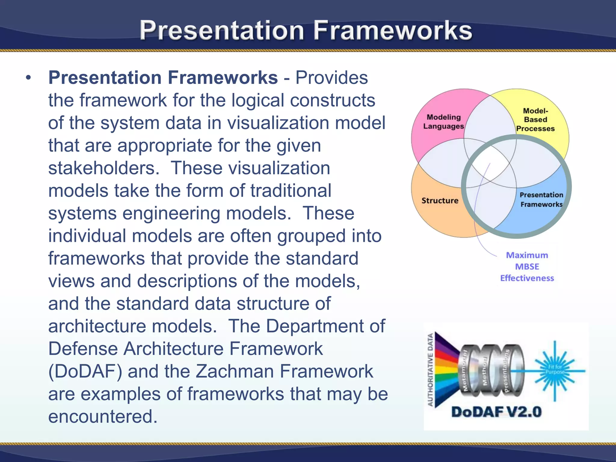
• Presentation Frameworks- Provides
the framework for the logical constructs
of the system data in visualization model
that are appropriate for the given
stakeholders. These visualization
models take the form of traditional
systems engineering models. These
individual models are often grouped into
frameworks that provide the standard
views and descriptions of the models,
and the standard data structure of
architecture models. The Department of
Defense Architecture Framework
(DoDAF) and the Zachman Framework
are examples of frameworks that may be
encountered.
24.
24
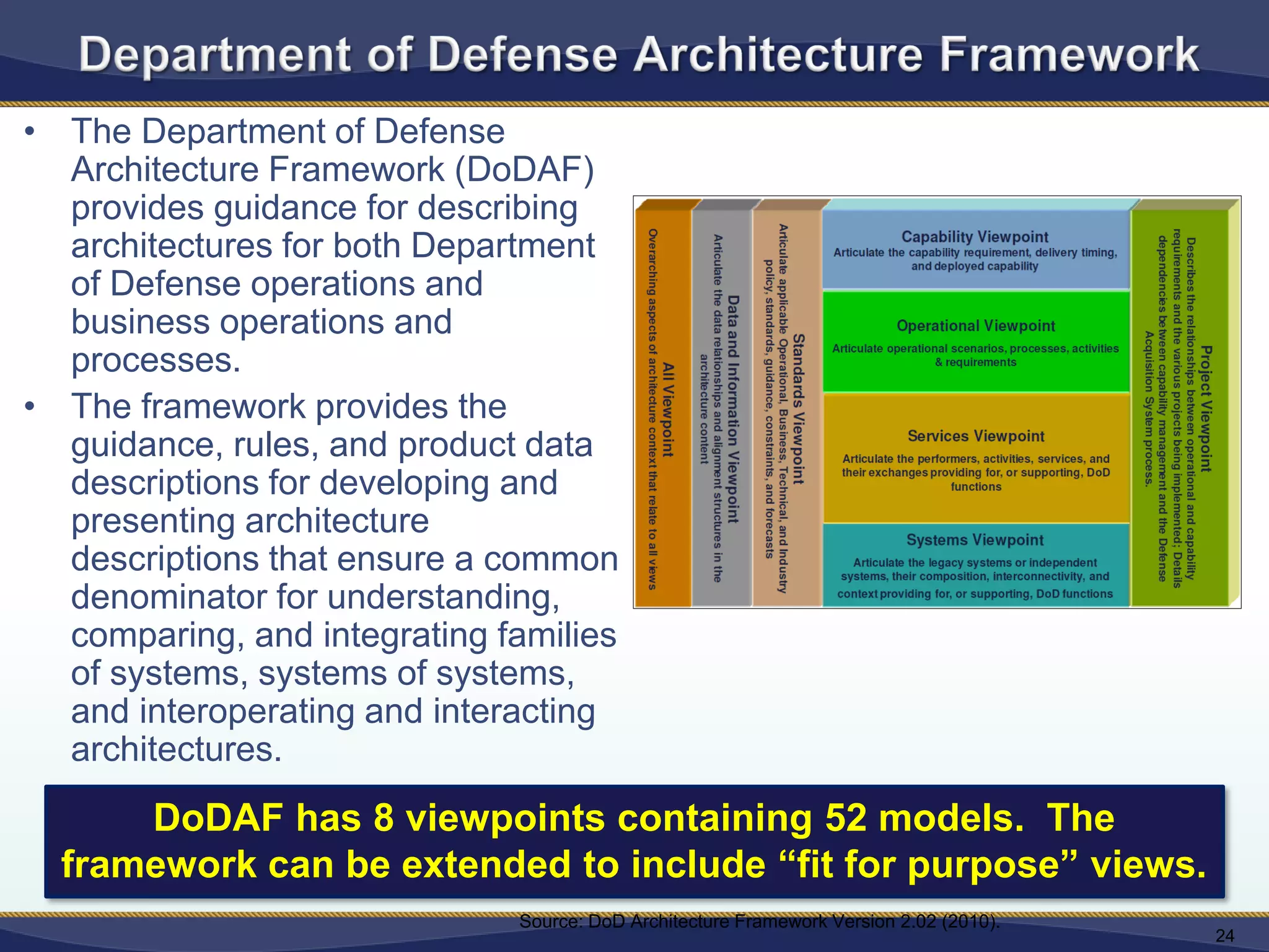
Source: DoD ArchitectureFramework Version 2.02 (2010).
DoDAF has 8 viewpoints containing 52 models. The
framework can be extended to include “fit for purpose” views.
• The Department of Defense
Architecture Framework (DoDAF)
provides guidance for describing
architectures for both Department
of Defense operations and
business operations and
processes.
• The framework provides the
guidance, rules, and product data
descriptions for developing and
presenting architecture
descriptions that ensure a common
denominator for understanding,
comparing, and integrating families
of systems, systems of systems,
and interoperating and interacting
architectures.
26
• Model-Based SystemsEngineering
Tools are general purpose software
products that use modeling
languages, and support the
specification, design, analysis,
validation and verification of
[complex] system representations.
27.
27
Ensure focus onthe vision
Ensure that the stakeholders
needs are clearly understood,
prioritized and addressed
Manage complexity
Support engineering
decisions (cost, schedule
and technical)
Manage change
Identify critical details
that need special
consideration/mitigation
28.
“I must sounda note of caution
though with respect to
[modeling], both technical and
programmatic. They are a
useful tool to support decision-
making but they should always
be continually updated as new
information comes to hand and
importantly, they should never
completely supplant the
wisdom of corporate knowledge
held by the “grey beards” of an
[organization].”
28
Senator David Fawcett – Parliament of Australia
31
31
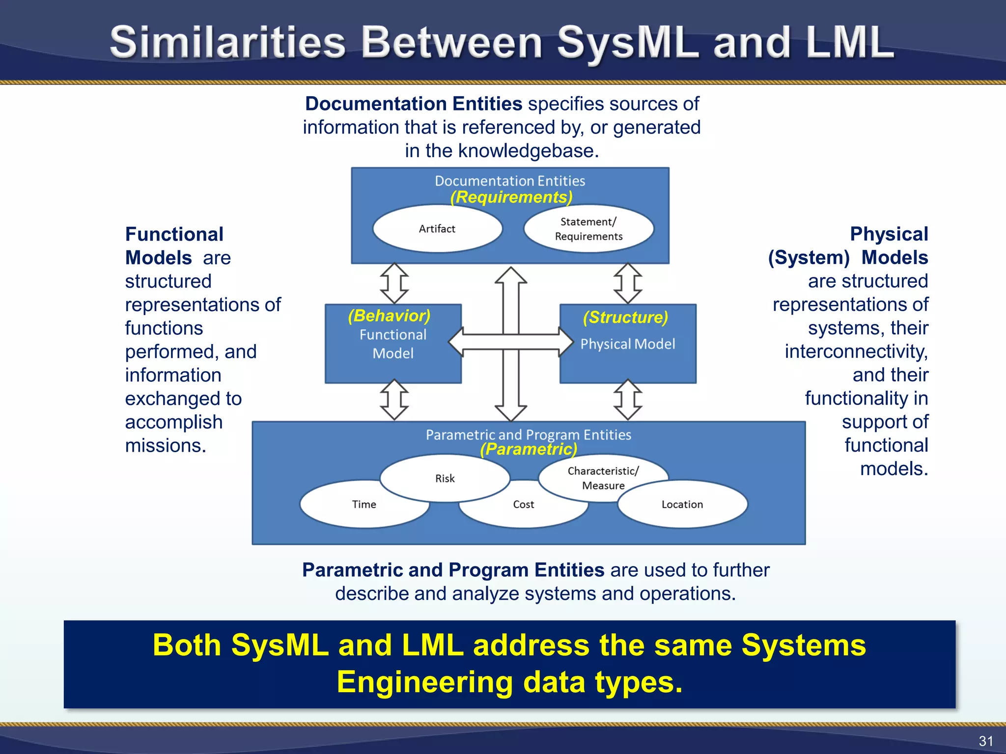
Functional
Models are
structured
representations of
functions
performed,and
information
exchanged to
accomplish
missions.
Physical
(System) Models
are structured
representations of
systems, their
interconnectivity,
and their
functionality in
support of
functional
models.
Documentation Entities specifies sources of
information that is referenced by, or generated
in the knowledgebase.
Parametric and Program Entities are used to further
describe and analyze systems and operations.
(Parametric)
(Structure)(Behavior)
(Requirements)
Both SysML and LML address the same Systems
Engineering data types.
32.
Both SysML andLML have corresponding visual
representations of Systems Engineering data types.


![26
• Model-Based Systems Engineering
Tools are general purpose software
products that use modeling
languages, and support the
specification, design, analysis,
validation and verification of
[complex] system representations.](https://image.slidesharecdn.com/specwebinarmbse-30aug2018-180903124616/75/Model-Based-Systems-Engineering-Demystified-26-2048.jpg)

![“I must sound a note of caution
though with respect to
[modeling], both technical and
programmatic. They are a
useful tool to support decision-
making but they should always
be continually updated as new
information comes to hand and
importantly, they should never
completely supplant the
wisdom of corporate knowledge
held by the “grey beards” of an
[organization].”
28
Senator David Fawcett – Parliament of Australia](https://image.slidesharecdn.com/specwebinarmbse-30aug2018-180903124616/75/Model-Based-Systems-Engineering-Demystified-28-2048.jpg)


![[Capella Day 2019] Integrating Capella, SCADE and medini analyze, for MBSE, E...](https://cdn.slidesharecdn.com/ss_thumbnails/20190916capelladayscadev3ansys-190919144158-thumbnail.jpg?width=640&height=640&fit=bounds)