Optical Coherence Tomography dr md toufiqur rahman cardiologist
•Download as PPT, PDF•
11 likes•2,061 views

Optical Coherence Tomography dr md toufiqur rahman cardiologist

Recommended
More Related Content
What's hot
What's hot (20)
Similar to Optical Coherence Tomography dr md toufiqur rahman cardiologist
Similar to Optical Coherence Tomography dr md toufiqur rahman cardiologist (20)
More from PROFESSOR DR. MD. TOUFIQUR RAHMAN
More from PROFESSOR DR. MD. TOUFIQUR RAHMAN (20)
Recently uploaded
Recently uploaded (20)
Optical Coherence Tomography dr md toufiqur rahman cardiologist
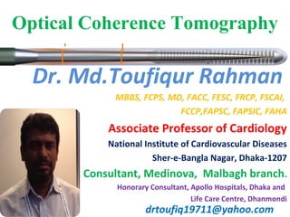
- 1. Dr. Md.Toufiqur Rahman MBBS, FCPS, MD, FACC, FESC, FRCP, FSCAI, FCCP,FAPSC, FAPSIC, FAHA Associate Professor of Cardiology National Institute of Cardiovascular Diseases Sher-e-Bangla Nagar, Dhaka-1207 Consultant, Medinova, Malbagh branch. Honorary Consultant, Apollo Hospitals, Dhaka and Life Care Centre, Dhanmondi drtoufiq19711@yahoo.com Optical Coherence Tomography
- 2. Introduction of OCT • James G. Fujimoto, 1991 • What is OCT: diagnostic medical imaging techonology • Why OCT: better diagnose and treat disease • Main application areas: heart disease and cancer drtoufiq19711@yahoo.com
- 3. What is OCT(Optical Coherence Tomography)? • OCT use low-coherence interferometry to produce a two or three dimensional image of optical scattering from internal tissue microstructures. • Michelson interferometer is used to perform low-coherence interferometry • OCT measures intensity of reflected infrared light. drtoufiq19711@yahoo.com
- 6. fundamental OCT Schematic SLD Sample Reference Demodulator AD Computer Detector PZT drtoufiq19711@yahoo.com
- 7. Advantages of OCT • Broad dynamic range • High resolution • Rapid data acquisition rate, • Small inexpensive catheter/endoscope design • Compact portable structure (fiber optically based, making possible the development of small catheters and endoscopes) • The frame rate for OCT systems are four to eight frames per second.(assume an image size of 256 by 512 pixels.) drtoufiq19711@yahoo.com
- 8. Nowadays and future equipment DISPLAY AND KEYBOARD INTEROMETER ELECTRONICS AND OPTICS +COMPUTER FIBEROPTIC PROBE •Low-coherence Superluminescent diode:800 –1300 nm center waveength and severl milliwatts power. drtoufiq19711@yahoo.com
- 9. 9 Development of OCT 2004 2007 2009H H2011 2012 M2 System M3 System C7XR™ System ILUMIEN™ System ILUMIEN™ OPTIS™ First Commercial OCT System 15 fps / 200 lines Occlusion + flush 2nd Generation 20 fps / 240 lines Occlusion + flush Europe and US only 100 fps / 500 lines Occlusion-free Commercially available 2011 100 fps / 54 mm pullback Combined FFR and OCT Wireless FFR Japan launch 2012 180 fps/75 and 54 mm pullback Advanced software tools for PCI Optimization Tableside control from DOC Occlusion balloon + ImageWireTM Occlusion-free Flush FFR and OCT System 2nd Gen FFR and OCT System drtoufiq19711@yahoo.com
- 10. 10 OCT Technology from St. Jude Medical • Console • Rapid exchange (Rx) imaging catheter • Contrast flush; balloon occlusion not required • Fast image acquisition: 7.5cm pullback in 2.5 sec drtoufiq19711@yahoo.com
- 11. Physician’s Monitor DOC Removable Tray Connector Panel Service Access Panel Wheel Locks Main Power Cord Connector Main Power Switch Physician’s Side 11 ILUMIEN™ – Console Overview Operator’s Monitor Keyboard CD/DVD Drive Fan Filter Hibernate/ wake-up button Mouse Chart Holder Operator’s Side drtoufiq19711@yahoo.com
- 12. 12 DRAGON-FLY DUO CATHETER • Fiber optic • Three radioparque marker • Compatible with G.C 6 or 7 Fr without holes • G.W 0.14” drtoufiq19711@yahoo.com
- 13. OCT in Nontransparent Tissue A epiglottis B arterial layers C atherosclerotic plaques drtoufiq19711@yahoo.com
- 14. OCT application A Reduce High False-Negative Rates B Reduce Biopsy Hazardous Applied in guiding microsurgical procedure Esophagus & epithelium & early cancer Vulnerable plaque Prostate drtoufiq19711@yahoo.com
- 15. Limitation • Penetration: 2-3mm Ideal: 4mm • Resolution : catheter/endoscope based image: 10μm, noncatheter: 4 μm, 1. femtosecond laser is expensive (1 μm) 2. transverse resolution needs to be similar to axial resolution, below 10 μm need short confocal parameter which results in the focus falling off rapidly. • Acquisition rate: <10franes/second • Lack of large-scale clinical trials drtoufiq19711@yahoo.com
- 16. Extention and application of OCT Name Work Research Application Dr. Zhongping Chen University of California, Irvine Doppler OCT studying blood vessel function and fluid flow, generally in small structures. Dr. Johannes de Boer Massachusetts General Hospital (MGH) polarization-sensitive OCT diagnosing burns and guiding appropriate treatment Dr. Brett Bouma and Dr. Guillermo Tierney MGH very portable, high- performance OCT systems for clinical diagnostic studies major clinical investigations are ongoing in the fields of gastroenterology, dermatology, cardiology, urology, orthopedics, gynecology, and otolaryngology. drtoufiq19711@yahoo.com
- 17. 17 Application of OCT in Cardiology Pre- PCI PCI POS- PCI drtoufiq19711@yahoo.com
- 18. 18 Prior to Starting a Case Required Materials – Dragonfly™ Duo imaging catheter – Sterile DOC cover – 3 ml purge syringe – Contrast media indicated for coronary use – 0.014" guidewire – Guide catheter (6-7 F, with no sideholes) PROCEDURE OF OCT drtoufiq19711@yahoo.com
- 19. 19 Turning ON the System – Power Switches Powerup / Wake-up button on upper right of keyboard . Main Switch next to power cable Tech. Procedure drtoufiq19711@yahoo.com
- 20. 20 Entering patient data Tech. Press Add new patient data. Put all the information's concerning the patient. Press New OCT Recording. Procedure drtoufiq19711@yahoo.com
- 21. 21 Catheter Preparation • Purge with contrast until 3-5 drops exit distal tip. Procedure drtoufiq19711@yahoo.com
- 22. 22 Catheter Preparation • Remove the hoop carefully from the catheter Procedure drtoufiq19711@yahoo.com
- 24. 24 Connecting Catheter to DOC Counter clockwise clockwise Procedure drtoufiq19711@yahoo.com
- 25. Catheter Preparation Insert the DOC into the sterile bag. Scrub Tech Fix the DOC by her hand and the Technician pull the sterile cover. Place it on the table. Procedure drtoufiq19711@yahoo.com
- 26. 26 Preparations • Watch the five yellow LEDs light up on the DOC Procedure drtoufiq19711@yahoo.com
- 28. 28 Preparations Of Calibaration Press Live View Ask the physician to put his 2 fingers to calibrate the catheter Press Auto-Calibrate , The system is calibrated automatically Procedure drtoufiq19711@yahoo.com
- 29. Stop Button Unload Button Laser Emission Symbol Advance Button Pullback Button Pullback Position LEDs Load LED Drive Motor Optical Controller (DOC) – Overview 29 Procedure drtoufiq19711@yahoo.com
- 30. 30 Pullback Preparation – Purge the Catheter • If blood enters the catheter lumen, purge with the attached 3 cc contrast syringe. Blood in catheter lumen Purged catheter lumen Procedure drtoufiq19711@yahoo.com
- 31. 31 Preparation of Injection Recommended Settings: • Injection by hand • Left coronary, Right coronary arteries: (16----20) ml ; • We can use 12-20 ml syring In your Cath. (Depend on operator) • When the operator is ready to inject contrast, click the “Enable Pullback ” button. • Ask the Physician to inject, 3 sec from the injection and when the image is clear press ”Start Pullback” Procedure drtoufiq19711@yahoo.com
- 32. 32 Performing a case Procedure drtoufiq19711@yahoo.com
- 33. 33 Pullback Preparation – Puff into the Vessel • During live scan, puff with the contrast injector to determine guiding catheter position for optimal image clarity. Suboptimal clearance, blood swirls Optimal clearance Procedure drtoufiq19711@yahoo.com
- 34. 34 Reviewing an Acquired Image Procedure drtoufiq19711@yahoo.com
- 40. 40 New Recording for the same patient Press New Recording Ask again the physician to put his 2 fingers to do calibration Repeat the same step of the Injection Procedure drtoufiq19711@yahoo.com
- 42. 42 Ending Procedure • Press “Unload” to disconnect catheter Procedure drtoufiq19711@yahoo.com
- 43. • Detect the Thrombus , not detected with Angio – Image • Rapture Plaque • Differentiate between the Red and white Thrombus • Stent Thrombosis and Malappositon Post Procedure Findings of OCT drtoufiq19711@yahoo.com
- 45. Thrombus 45 White Thrombus Red Thrombus drtoufiq19711@yahoo.com
- 47. Progress in coronary image • Coronary angiography CAG • Intravascular ultrasound IVUS • Optical coherence tomography OCT IVUS-guided implantation of stentIVUS-guided implantation of stent has been showed to improve thehas been showed to improve the outcomes with reduction of restenosisoutcomes with reduction of restenosis and thrombosisand thrombosis What is the role of OCTWhat is the role of OCT drtoufiq19711@yahoo.com
- 48. • The most prominent feature of OCT is its high resolution of 10µm. It enables real-time, full tomographic, in-vivo of vessel visualization mainly used in the following microstructure: 1. Fibrous cap and evaluate vulnerable plaque1. Fibrous cap and evaluate vulnerable plaque 2. Strut apposition and stent tissue coverage2. Strut apposition and stent tissue coverage drtoufiq19711@yahoo.com
- 49. A very strong correlation between histology and OCT measurements Lipid-rich plaque Fibrous plaque Thin cap fibroatheroma drtoufiq19711@yahoo.com
- 50. Classification of strut apposition by OCT Totally embedded strut Embedded subintimally without disruption of lumen contour Completely embedded with disruption of lumen contour Partially embedded with extension of strut into lumen Complete strut malapposition (blood able to exist between strut and lumen wall) Type I Type II Type IIIa Type IIIb Type IV Giulio. CCI, 2008, 72:237–247 drtoufiq19711@yahoo.com drtoufiq19711@yahoo.com
- 51. Different vessel responses observed in multiple frames Well apposed struts with uniform neointimal coverage Well apposed struts with not-uniform vessel response around some strut. Although fully covered, struts located from 9 to 12 o’clock present a signal attenuation of the tissue around them Deeper increase toward the media of the area of signal attenuation in the proximal cross section Giulio. CCI, 2008, 72:237–247drtoufiq19711@yahoo.com
- 52. New finding with OCT in the recent clinical studies are changing our views drtoufiq19711@yahoo.com
- 53. Novel neointimal formation over sirolimus- eluting stents identified by coronary angioscopy and optical coherence tomography Daisuke Murakami (MD)a , Masamichi Takano (MD)b,∗ , Masanori Yamamoto (MD)a , Shigenobu Inami (MD)a , Takayoshi Ohba (MD)a , Yoshihiko Seino (MD, FJCC)a , Kyoichi Mizuno (MD, FJCC)b Murakami, et al. Journal of Cardiology 2009, 53:311—313 drtoufiq19711@yahoo.com
- 54. Typical findings of angioscopy, and OCT after BMS implantation (A)Six-month follow-up angiogram shows no in-stent restenosis (B) Angioscopy shows white neointima covers completely over the BMS and the struts are invisible (C) Circumferential stent struts with strong signals are identified by cross-sectional image of OCT. Neointima inside the struts has uniform signals without their attenuation 3.5mm×13mm Male, A 43-year-old with SAP BMS in LAD Journal of Cardiology , 2009, 53:311—313 drtoufiq19711@yahoo.com
- 55. Novel findings of angioscopy and OCT after SESs implantation (A)Six-month follow-up angiogram shows no in-stent restenosis (B) Angioscopy shows yellow neointima covers over the SES , whereas some of the struts are uncovered in the proximal overlapping segment. (C) In this overlapping segment, thin membranous structure inside the struts of inner stent is partially recognized by optimal coherence tomography. Neointima has strong signalswith their rapid attenuation similar to a lipid plaque. Although struts of inner stent are clearly seen, those of outer stent are not visible owing to backscattering of the neointima. SESs deployed in LAD Journal of Cardiology , 2009, 53:311—313 drtoufiq19711@yahoo.com
- 56. • OCT signal patterns of the neointima showed rapid attenuation similar to lipid tissues in atherosclerotic lesions • neointima within the SES is quite different from that of the BMS and may contain atherosclerotic components Murakami, et al. Journal of Cardiology 2009, 53:311—313 drtoufiq19711@yahoo.com
- 57. OCT and intravascular ultrasound imaging was performed at corresponding sites in patients undergoing catheterization. OCT plaque characteristics for lipid content, fibrous cap thickness, and macrophage density were derived using previously validated criteria. Thin-cap fibroatheroma (TCFA) was defined as lipid-rich plaque (two or more quadrants) with fibrous cap thickness <65 µm. Remodelling index (RI) was calculated as the ratio of the lesionto the reference external elastic membrane area. A total of 54 lesions from 48 patients were imaged.Positive remodelling compared with absent or negative remodelling was more commonly associated with lipid-rich plaque (100 vs. 60 vs. 47.4%, P = 0.01), a thin fibrous cap (median 40.2 vs. 51.6 vs. 87 µm, P = 0.003) and the presence of TCFA (80 vs. 38.5 vs. 5.6%, P < 0.001). Fibrous cap macrophage density was also higher in plaques with positive remodelling showing a positive linear correlation with the RI (r = 0.60, P < 0.001). Eur Heart J. 2008, 29: 1721–1728 drtoufiq19711@yahoo.com
- 58. ODESSA: 6-month OCT long lesions randomized to multiple SES, PES, ZES and BMS 6968 cross-sections6968 cross-sections 53047 struts53047 struts malapposedmalapposed uncovereduncovered BMSBMSSESSES PESPES ZESZES Guagliumi, et al. TCT 2008Guagliumi, et al. TCT 2008 drtoufiq19711@yahoo.com
- 59. Human OCT Study 100% of Endeavor Stent Struts Covered at 6 Months Stent struts are apposed to vessel wall with uniform stent coverage 100% 24,076 Endeavor struts were uniformly covered Distribution of Endeavor Struts Condition ZES= 44 24,076 stent struts Guagliumi et al. ESC 2008 drtoufiq19711@yahoo.com
- 60. Six-month strut coverage and vessel wall response of the zotarolimus eluting stent compared with driver bare mental stent implanted in AMI A prospective, randomized, controlled study proformed with OCT OCTAMI Guagliumi, et al. TCT 2009 drtoufiq19711@yahoo.com
- 61. Primary end point % uncovered struts on per patient basis Guagliumi, et al. TCT 2009 drtoufiq19711@yahoo.com
- 62. Secondary end point mas length of uncovered and incompletely apposed segments (mm) in OCT Guagliumi, et al. TCT 2009 drtoufiq19711@yahoo.com
- 63. Secondary end point strut level NIH and net volume obstruction in OCT Guagliumi, et al. TCT 2009drtoufiq19711@yahoo.com
- 64. OCT image to ACS : 9-year after BMS implantation OCT pullback from mid-proximal LCX TFCA overlying a large lipid-rich plaque drtoufiq19711@yahoo.com
- 65. Thank you All
Editor's Notes
- What is oct Optical Coherence tomography (OCT) is a light based imaging modality with superior spatial resolution (~ 15Um) compared to other intravascular imaging system. This technology does not use x-ray The acquisition of this image is fast and easy to treat In other hand other type of coronary imaging is difficult to interpret and doesn&apos;t have the high resolution So the high resolution of oct makes it an excellent tool to visualize the vasculature Who that
- We have long history of OCT, competition is new to the field
- In order to perform OCT procedures, St. Jude Medical provides a console (C7-XR™) and an imaging catheter (Dragonfly™). With the current C7-XR technology, no balloon occlusion is required; rather, the vessel is cleared of blood for imaging by a rapid flush of contrast. The images themselves are acquired extremely quickly: acquiring a 5 cm pullback image takes only 2.5 seconds.
- Long pullback : 75mm ; old one : 55mm 3 markeres : lens marke visible during the pullback ; distal and proximal to guide the phyisican on the best position The old : only 2 markres : distal and proximal markers ; to help the physician more and more to know where is the good position
- The ilumien system incorporat the most advanced oct techology to optmize PCI and visulazie the vessel anatomy How that By ……
- Choose existing patient or add new patient, and then choose New OCT Recording.
- Remove the hoop carefully from the catheter. To avoid damage, grasp the proximal end of the catheter at the side port and hold firmly with your thumb and forefinger. With the other hand, gently twist and pull the hoop to release the catheter. Do not twist and pull the catheter. While withdrawing it from the hoop, gently wipe the catheter shaft with a compress moistened with heparinized saline. This activates the hydrophilic coating and prevents the catheter from spinning dry, causing possible fiber breaks. Handle carefully to prevent kinking the catheter.
- Once the catheter has been purged, it can be connected to the DOC.Remove the blue protective cap from the catheter hub by twisting the cap counterclockwise. Open the black connector cover on the front of the DOC. Align the four catheter hub sprockets inside the DOC connection port; turn clockwise until secure. Care should be taken not to touch the fiber optic core of the catheter and not to kink or bend the catheter.
- Insert the DOC into the sterile bag and place it on the table. NOTE: This step requires two people, one sterile and one nonsterile.
- The screen will show the status of the connecting catheter, and the LED on the DOC will light up (see next slide).
- When the catheter is fully connected, this will be indicated on the screen.
- This is the DOC, which stands for Drive Motor and Optical Controller. The controls and indicators are: Load LED – Operator can attach or remove catheter when fully lit (not blinking) Unload – Press to unload imaging catheter Laser Emission Symbol – Illuminated when laser output is switched on Stop – Stops the imaging catheter motion and turns off laser output Advance – Starts or stops the optical fiber advance sequence Pullback – Starts or stops the optical fiber pullback sequence Pullback Position LEDs – Relative position of the optical carriage along the pullback range Once the DOC has been placed in a sterile pouch, it is ready for use together with a sterile Dragonfly imaging catheter.
- Once an image has been acquired, use the toolbar below the image to: Play, pause, stop, move by frame or move by 1 mm segments Add or delete bookmarks Jump from bookmark to bookmark Export images and bookmark frames of interest The system will automatically play back at a default speed of 1 mm/sec. The optical fiber automatically advances to the original distal position.
- Once acquisition of a segment is complete, you still have the possibility to adjust calibration. Calibration may be adjusted either to a chosen frame and proximal or to the entire recorded segment.
- Once acquisition of a segment is complete, you still have the possibility to adjust calibration. Calibration may be adjusted either to a chosen frame and proximal or to the entire recorded segment.
- Click the T icon to add a note to that frame.
- When the imaging session is finished, the unload button must be pressed on the DOC to release the catheter. If the Unload button is not pressed before attempting to remove the catheter, part of the catheter will remain locked into the DOC, which can damage the DOC.