Control Home Appliances With Your Phone
•Download as DOCX, PDF•
0 likes•138 views

cellphone bases power control

Recommended
More Related Content
What's hot
What's hot (20)
Similar to Control Home Appliances With Your Phone
Similar to Control Home Appliances With Your Phone (20)
Recently uploaded
Recently uploaded (20)
Control Home Appliances With Your Phone
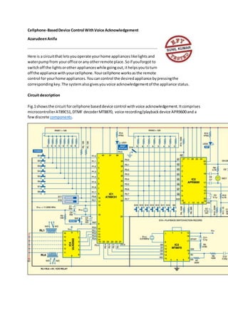
- 1. Cellphone-BasedDevice Control WithVoice Acknowledgement AzarudeenAnifa Here is a circuitthat letsyouoperate yourhome applianceslikelightsand waterpumpfrom youroffice orany otherremote place.Soif youforgot to switchoff the lightsorother applianceswhile goingout,ithelpsyoutoturn off the appliance withyourcellphone.Yourcellphone worksasthe remote control for yourhome appliances.Youcancontrol the desiredappliance bypressingthe correspondingkey.The systemalsogivesyouvoice acknowledgementof the appliance status. Circuit description Fig.1showsthe circuit forcellphone baseddevice control withvoice acknowledgement.Itcomprises microcontrollerAT89C51,DTMF decoderMT8870, voice recording/playbackdevice APR9600and a fewdiscrete components.
- 2. Fig.1: Circuit for cellphone-baseddevice control with voice acknowledgement
- 3. MicrocontrollerAT89C51 is at the heart of the circuit.It is a low-power,high-performance,8-bit microcontrollerwith4kB of flashprogrammable anderasable read-onlymemory(PEROM) usedas on-chipprogrammemory,128 bytesof RAMusedas internal datamemory,32 individually programmable input/output(I/O) linesdividedintofour8-bitports,two16-bitprogrammable timers/counters,afive-vectortwo-level interruptarchitecture,on-chiposcillatorandclockcircuitry. A 11.0592MHz crystal (XTAL1) is used to provide basic clock frequency for the microcontroller. Capacitor C3 and resistor R3 form the power-on reset circuit, while push-to-on switch S20 is used for manual reset. Port pins P1.0 through P1.7 of the microcontroller are configured to get the input from push-to-on switches S1 through S8. Pins of Port P1 are pulled high via resistor network RNW1. Port pins P2.0 through P2.4 are configured to receive the decoded DTMF signal from DTMF receiver MT8870. The functions of the corresponding switches (S1 through S8) and cellphone keys are shown in Table I. The DTMF decoder is used for decoding the mobile signal. It gets DTMF tone from the mobile headset’s speaker pins and decodes it into 4-bit digital signal. The DTMF decoder is operated with a 3.579MHz crystal (XTAL2 ) InDTMF receiverMT8870 (IC3),capacitorC12 is usedto filterthe noise andresistorsR6and R7 helpto amplifythe inputsignal usingthe internal amplifier. Pin16 of IC3 connectedtoresistorR5 providesthe earlysteeringoutput.Itgoeshighimmediately whenthe digital algorithmdetectsavalidtone pair(signal condition).Anymomentarylossof signal conditioncausesEStto returnto lowstate. Pin17 of IC3 connectedtocapacitor C11 isbidirectional,actingassteeringinput/guardtime output (St/GT).A steeringlogicVTSt detectedatSt causesthe device toregisterthe detectedtone pair.The guard time outputresetsthe external steeringtime constant,anditsstate isa functionof ESt and the voltage at St. Port P3 pinsP3.6 and P3.7 of IC1 are configuredtoselectthe control source forthe devices.These are connectedtoDIPswitchesS17 and S18 and pulledhighviaresistorsR2and R1, respectively. Here,we are usingtwocontrol sources,switchesandmobile’skey.DIPswitchesS17and S18 select the control sourcesas showninTable II.
- 4. Pin2.5 of Port P2 is configuredtoshowthe reststatus. That is,if none of the control sourcesis selectedbyDIPswitchesS17and S18, LED1 glows.ResistorR14limitsthe currentthroughLED1. Voice acknowledgementisprovidedbythe APR9600 (IC2).Itis a single-chipvoice recordingand playbackdevice thatcan recordand playmultiple messagesatrandomorin sequential mode for60 seconds.The usercan selectsample rateswithcorresponding qualityrecordinglengths. Microphone amplifier,automaticgaincontrol (AGC) circuits,internal anti aliasingfilter,internal outputamplifierandmessage managementare some of the featuresof the APR9600. Here the APR9600 isconfiguredinrandom-accessmode,whichsupportstwo,fourandeight messagesof fixeddurations.The lengthof eachmessage isthe total recordinglengthavailable dividedbythe total numberof memorysegments/tracksenabled. AudioprocessorAPR9600 can store upto eightvoice messages.PortP0pinsandP2.7 are configured to communicate withIC2.PortP0 pinstriggerselectionof the message.PortpinP2.7is the input signal toidentifywhetherthe voice message isplayingornot. Fig.2: Pin configuration of mobile headset PinsP3.0 throughP3.5 of Port P3 control the deviceswiththe helpof relaysRL1throughRL6 via relaydriverIC4. A speakerisconnectedtoIC2 foraudiooutput.The speakeroutputdrivesthe micinputof the mobile foraudioacknowledgement.Anelectretmicrophone MIC1isconnectedtoIC2 to recordthe voice inIC2. LED2 flashestoshowthe busystatusof IC2 duringrecordingandplayback.The audio messagestobe recordedinAPR9600, byusingtriggerswitchesS9through S16, are showninTable III.SPST switchS19 is closedforrecordingandswitchS19 isopenedforplayback.
- 5. Fig.3showsthe powersupplycircuit.The 230V ACmainsis steppeddownbytransformerX1to deliverthe secondaryoutputof 9V,500 mA.The transformeroutputisrectifiedbyafull-wavebridge rectifiercomprisingdiodesD1throughD4, filteredbycapacitorC16 and thenregulatedbyIC7806 (IC5).CapacitorC15 bypassesthe ripplespresentinthe regulated6V powersupply.LED3acts as a power-onindicatorandresistorR16limitsthe currentthroughLED3. Fig.3: Power supplycircuit An actual-size,single-side PCBforcellphone-baseddevice control withvoice acknowledgement is shownin Fig.4(ViewasPDF) andits componentlayoutin Fig.5(View asPDF). Download Source code:clickhere Recording and playback To record the voice inIC2, followTable III.Close SPSTswitchS19to make pin27 of IC2 low. Thereafter,pressandholdswitchesS9throughS16 to record correspondingvoice messages.LED2 flashestoindicate audiorecording. For playbackof any device status,openSPSTswitchS19 andpressthe correspondingswitch(S9 throughS16). The recordedaudiocanbe heardfromthe speakerconnectedtopins14 and 15 of IC2. Fig.2showsthe pin configurationof mobile headset.
- 6. Software The program (Device_Control.BAS) forthe microcontrolleriswrittenusingBASCOMmicrocontroller programmingsoftware.Inthe program,first,initialise the port(P0-P3) forcorrespondingcontrols. Thereafter,declare the variablesforthe program.Afterdeclaration,assignsome initial valueto variables.Here,microcontrollerportsare initialisedtomake all the devices‘off’initially. Afterthat,the main functionchecksthrough‘Do’loopwhichcontrol source hasbeenenabledby usingDIPswitchpins.If you selectswitchS17,it searchesthe inputfromthe mobile only.If you selectswitchS18,it searchesthe inputfromthe switches(S1throughS8) only.If youenable both switchS17 andswitchS18, itsearchesthe inputsfromswitchesandmobile.Else,the rest-status LED1 glows.RefertoTable IIto selectthe control source. The mobile signal isdecodedintothe DTMFsignal byIC3. The DTMF outputfor each mobile key (usedinthisproject) pressedisshowninTable IV. Aftergettingthe inputfromthe switchesormobile,the programgoestothe device_action subroutine andexecutesthe correspondingaction(referTable I). The device_actionsubroutine changesthe statusof the device andcallsthe voice_alertsubroutine. The voice_alertsubroutinechecksthe device statusanddevice name fromthe source inputand controlsthe correspondingpinsof IC2.First,itselectsthe voice signal forthe device name.After playingthat,itselectson/off statusof correspondingdevice asmentionedinTable III. If you press‘*’ keyfollowedbythe device numberonyourmobile handset,itwill notchange the statusof that device andinformthe currentdevice status.If youpressdevice numberfollowedby‘*’ keyon yourmobile handset,itwillchange the statusof that device andinformthe changeddevice status.‘#’ keycontrolsthe voice_control subroutine andactslike amute key. EFY note. The source code of thisprojectis available onthe linkgivenbelow. http://www.efymag.com/admin/issuepdf/DeviceControlWithVoiceAcknowledgement.zip