1. • Mount the controller to a solid surface with the mounting bars provided.
• The controller must be mounted vertically with the “TOP” up to operate properly.
• Mount the controller away from sources of heat and direct exhaust of engines.
• Allow enough room around the controller & resistor bank for air circulation.
• Route electrical wires through the bottom of the enclosure and connect
securely tot he terminals.
• All electrical circuits must be free from grounds and shorts.
• Remove shipping material from the arc shields before operating the controller.
• The resistor bank must be mounted separately. Provide a cover for the
resistor bank to protect it from the weather & dirt.
• The timers are factory preset for magnets rated 150-200 A: TR1=1.25 s;
TR2=3.5 s
• For magnets rated below 150 A: TR1=0.75 s; TR2=2.0 s.
• Make additional minor timer adjustments to TR2 for optimal drop characteristics
to suit material being handled.
Procedure Start with the dial set at low range. Pick up and drop a load of the
material to be handled. If the material does not completely fall off the magnet,
increase the adjustment and try another load. If the material drops off and
then some jumps back up to the magnet before it can fall free, reduce the
adjustment and try another load. When all the material falls cleanly from the
magnet, the controller is properly set.
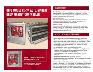
INSTALLATION, MAINTENANCE,
AND PARTS BULLETIN
OPERATING RANGE 100-200 A
(COLD MAGNET CURRENT)
The RD-3A Controller is a heavy duty magnet controller used for
magnets whose cold current ranges from 100 A to 200 A dc. Cold
current references the current flowing through the magnet when the
magnet temperature is 25°C throughout.
AUTOMATIC DROP
A reverse current adjustment provides for a fast. clean drop of the
magnet over the complete range of magnetic material with one
movement of the master switch or push button
MANUAL DROP
Allows for partial dropping of the load by controlling the amount of
reverse current to the magnet. A drop position on the master switch
or push button that is spring returned to off, gives the operator
complete control of the drop cycle.
OHIO MODEL RD-3A AUTO/MANUAL
DROP MAGNET CONTROLLER
DESCRIPTION
INSTALLATION PROCEDURES
6. RD-3A WIRING DIAGRAMS
NO QTY SYMBOL PART NUMBER DESCRIPTION
1 200 A-900235-03 35mm DIN MOUNTING RAIL
2 3 A-900254-12 RELAY SOCKET: 8 PIN
3 3 TR1-TR3 A-900568-34 RELAY: 2-DPDT; 240 V dc COIL
4 2 TR1-TR2 A-900573-27 TIMER:DELAY-OFF; 240 V dc
5 6 A-900567-07 JUMPER
6 2 A-900416-11 SCREW: M4 x 0.7 x 35mm
7 4 A-900118-35 FLATWASHER: M4
8 4 A-900115-28 LOCKWASHER: M4
9 2 A-900106-38 HEX NUT: M4 x 0.7 mm
10 15 A-950000-48 WIRE: 1.5MM2
(#16 AWG) NEOPRENE BLACK
11 6 A-900210-123 WIRE TERMINAL: 6mm (0.25 in) STUD
12 A-900210-109 WIRE TERMINAL: 8mm (0.31 in) STUD
13 3 A-900244-38 RELAY HOLD DOWN TY-WRAP
14 1 TR3 A-900573-31 TIMER: INTERVAL; 240 V dc
15
NO QTY SYMBOL PART NUMBER DESCRIPTION
1 200 A-900235-03 35mm DIN MOUNTING RAIL
2 3 A-900254-12 RELAY SOCKET: 8 PIN
3 3 TR1-TR3 A-900568-34 RELAY: 2-DPDT; 240 V dc COIL
4 3 TR1-TR3 A-900573-27 TIMER: DELAY-OFF; 240 V dc
5 6 A-900567-07 JUMPER
6 2 A-900416-11 SCREW: M4 x 0.7 x 35mm
7 4 A-900118-35 FLATWASHER: M4
8 4 A-900115-28 LOCKWASHER: M4
9 2 A-900106-38 HEX NUT: M4 x 0.7 mm
10 15 A-950000-48 WIRE: 1.5MM2
(#16 AWG) NEOPRENE BLACK
11 5 A-900210-123 WIRE TERMINAL: 6mm (0.25 in) STUD
12 A-900210-109 WIRE TERMINAL: 8mm (0.31 in) STUD
13 3 A-900244-38 RELAY HOLD DOWN TY-WRAP
14
15
NOTE:
1) Mounting hardware is for securing rail to controller panel
2) Use ty-wraps to secure wires in bundles.
3) Cut wires long enough to reach associated terminals.
4) Mark wire ends with proper terminal designations.
5) Set timer range for 0.2 - 3a. Set TR1 for 1a, TR2 for 1.5a and TR3 for 3a
6) L- is used on fixed voltage controllers, F-on variable voltage.
TIMER ASSEMBLY KIT 230 V dc SYS RD-3A
TIMED MANUAL CONTROLLER
NOTE:
1) Mounting hardware is for securing rail to controller panel
2) Use ty-wraps to secure wires in bundles.
3) Cut wires long enough to reach associated terminals.
4) Mark wire ends with proper terminal designations.
5) Set timer range for 0.2 - 3a. Set TR1 for 1a, TR2 for 1.5a
and TR3 for 3a
6) L- is used on fixed voltage controllers, F-on variable voltage.
6
3 120B010A12
TIMER ASSEMBLY KIT RD-3A SYS RD-3A
AUTOMATIC CONTROLLER
3 120B010A04
7. RD-3A WIRING DIAGRAMS
7
NO SYMBOL DESCRIPTION FUNCTION
1 A 150 A LIFT CONTACTOR MAIN LINE CONTACTOR
2 L 150 A LIFT CONTACTOR REDUCED POWER CONTACTOR
3 D 25 A DROP CONTACTOR REVERSE POWER CONTACTOR
4 TR3 D CONTACT ACTIVATE REVERSE CYCLE DELAY TIMER
5 TR2 L CONTACT DELAY OPEN REVERSE POWER ACTIVE TIMER
6 TR1 D CONTACT DELAY ACTIVATE REDUCED POWER ACTIVE TIMER
7 R1 POWER RESISTOR: 0.5 ⍀ x 2 REDUCED POWER RESISTOR
8 R2 POWER RESISTOR: 0.5 ⍀ x 2 REDUCED POWER RESISTOR
9 R3 POWER RESISTOR: 3.1 ⍀ x 2 REVERSE POWER RESISTOR
10 R4 POWER RESISTOR: 3.1 ⍀ x 2 REVERSE POWER RESISTOR
11 R5 POWER RESISTOR: 2.3 ⍀ x 4 MAGNET DISCHARGE RESISTOR
12 DM1,2 POWER DIODE ASSEMBLY R5 CUTOFF DURING LIFT
13 D1 ANTI-REVERSE CONTROL DIODE REVERSE POLARITY PROTECT
14 Z1-Z2 METAL OXIDE VARISTOR (MOV) DIODE VOLT SPIKE PROTECT
15 D2-D4 DISCHARGE DIODE LIMIT DISCHARGE SPIKE
NOTES:
1) Diodes D2 - D4 are mounted on the front side of the controller.
2) Timers are preset at factory for magnets rated above 150A.
3) Reduce timing on TR2 & TR3 for magnets rated below 150A.
See tabulation.
4) Make additional minor timing adjustments on TR3 for optimum
drop characteristics to suit the material being handled.
5) Set timer TR1 for 1 s.
6) Reference assembly diagram 120B010A04 for connections to relays.
8. RD-3A WIRING DIAGRAMS
NO SYMBOL DESCRIPTION FUNCTION
1 A 150 A LIFT CONTACTOR MAIN LINE CONTACTOR
2 L 150 A LIFT CONTACTOR REDUCED POWER CONTACTOR
3 D 25 A DROP CONTACTOR REVERSE POWER CONTACTOR
4 TR3 D CONTACT ACTIVATE REVERSE CYCLE DELAY TIMER
5 TR2 L CONTACT DELAY OPEN REVERSE POWER ACTIVE TIMER
6 TR1 D CONTACT DELAY ACTIVATE REDUCED POWER ACTIVE TIMER
7 R1 POWER RESISTOR: 1.0 ⍀ x 2 REDUCED POWER RESISTOR
8 R2 POWER RESISTOR: 1.0 ⍀ x 2 REDUCED POWER RESISTOR
9 R3 POWER RESISTOR: 3.1 ⍀ x 2 REVERSE POWER RESISTOR
10 R4 POWER RESISTOR: 3.1 ⍀ x 2 REVERSE POWER RESISTOR
11 R5 POWER RESISTOR: 2.3 ⍀ x 4 MAGNET DISCHARGE RESISTOR
12 DM1,2 POWER DIODE ASSEMBLY R5 CUTOFF DURING LIFT
13 D1 ANTI-REVERSE CONTROL DIODE REVERSE POLARITY PROTECT
8
NOTES:
1) Diodes D2 - D4 are mounted on the front side of the controller.
2) Timers are preset at factory for magnets rated above 150 A.
3) Reduce timing on TR2 & TR3 for magnets rated below 150 A.
See tabulation.
4) Make additional minor timing adjustments on TR3 for optimum
drop characteristics to suit the material being handled.
5) Set timer TR1 for 1 s.
6) Reference assembly diagram 120B010A12 for connections to relays.
9. NO SYMBOL DESCRIPTION FUNCTION
1 A 150 A LIFT CONTACTOR MAIN LINE CONTACTOR
2 L 150 A LIFT CONTACTOR REDUCED POWER CONTACTOR
3 D 25 A DROP CONTACTOR REVERSE POWER CONTACTOR
4 TR3 D CONTACT ACTIVATE REVERSE POWER ACTIVE TIMER
5 TR2 L CONTACT DELAY OPEN REDUCED POWER ACTIVE TIMER
6 TR1 D CONTACT DELAY ACTIVATE REVERSE CYCLE INTERLOCK
7 R1 POWER RESISTOR: 0.5 ⍀ x 2 REDUCED POWER RESISTOR
8 R2 POWER RESISTOR: 0.5 ⍀ x 2 REDUCED POWER RESISTOR
9 R3 POWER RESISTOR: 3.1 ⍀ x 2 REVERSE POWER RESISTOR
10 R4 POWER RESISTOR: 3.1 ⍀ x 2 REVERSE POWER RESISTOR
11 R5 POWER RESISTOR: 2.3 ⍀ x 4 MAGNET DISCHARGE RESISTOR
12 DM1 POWER DIODE ASSEMBLY R5 CUTOFF DURING LIFT
13 D1, D2 ANTI-REVERSE CONTROL DIODE REVERSE POLARITY PROTECT
14 Z1 METAL OXIDE VARISTOR (MOV) DM1 VOLTAGE SPIKE PROTECT
15 DM2 POWER DIODE ASSEMBLY BLOCK SPIKE FROM RECTIFIER
16 Z2 METAL OXIDE VARISTOR (MOV) DM2 VOLTAGE SPIKE PROTECT
17 D2-D4 DISCHARGE DIODE CONTAIN DISCHARGE SPIKE
18 TR1 ADJUSTABLE TIMER RELAY DROP ACTIVE DELAY
19 D1 ANTI-REVERSE CONTROL DIODE REVERSE POLARITY PROTECT
RD-3A WIRING DIAGRAMS
NOTES:
1) Timers are preset at factory for magnets rated above 150 A.
3) Reduce timing on TR2 & TR3 for magnets rated below 150 A.
See tabulation. Set TR1 for 1 s.
4) Make additional minor timing adjustments on TR3 for optimum
drop characteristics to suit the material being handled.
5) Set timer TR1 for 1 s.
6) Reference assembly diagram 120B010A04 for connections to relays.
9
10. RD-3A RESISTOR BANK DESCRIPTION AND SPECIFICATIONS
NO QTY PART NUMBER DESCRIPTION
1 1 120B005A8 RESISTOR BANK: RD-3A GRID TYPE
2 1 A-900550-26 MODULAR DOUBLE DIODE: 110A; 1.2 kV
3 2 018A2966Q MOV SUPPRESSOR ASSEMBLY
4 2 A-900413-10 SCR ASSY: M5 x 0.8 x 18mm
5 2 A-900106-39 HEX NUT: M5 x 0.8mm
6 A/R A-950009-01 HEAT SINK COMPOUND
7 7 A-900206-01 TERMINAL LUG
8
9
2 banks, each 650 x 330 x 206mm (25.5 x 13 x 8 in).
39620B endframes, bolt banks together.
Furnish jumper and 2 piece screened cover.
Heat shield per drawing 37836A.
Modified per drawing 39620A.
Replaces guyan #E-15345
DIODE MOUNTING INSTRUCTIONS:
1) Diode is mounted on the inside of enclosure frame in
space provided at the lower left corner of resistor bank.
2) Remove screen cover to access diode mounting area.
3) Before installing diode, remove factory installed shorting jumper
located on extended busbar.
4) Apply heat sink compound to bottom base of diode. Mount diode onto
frame with terminal #3 of diode mounted on top. diode mounting holes
will line up with existing holes in enclosure frame. secure diode to
enclosure frame with specified hardware.
5) Connect busbar to terminals #2 and #3 as shown using hardware
provided with diode.
6) Check for snugness of all fasteners.
10
11. AUTOMATIC CONTROLLER
1. When a signal is given by closing the contacts
between terminals “F” and “U”, the “A” coil and the
off-delay timer relay “TR2” are energized.
2. This closes the “A” contacts and applies full
power to the magnet.
3. The closing of the “TR2” contact energizes the
“L” coil; closing the “L” contacts and also
energizes the off-delay timer relay “TR1”.
4. The closing of the “TR1” contact energizes the off-
delay timer relay “TR3”.
5. The closing of the “TR1” contact energizes the
off-delay timer relay “TR3”..
6. When the “F” to “U” contact is broken, the “A”
coil is de-energized.
7. This opens the “A” contacts and sends current
through resistors “R1” and “R2” to drop the
magnet current to about half. The magnet will
also begin to discharge through DM1 and R5.
Timer “TR2” is also de-energized and begins to
time out .
8. Once timer “TR2” has completely timed out, its
contacts connected to timer “TR1” and coil “L”
open up. Coil “L” drops out and timer “TR1”
begins to time out. The magnet continues to
discharge through DM1 and R5.
9. When timer “TR1” completely times out the
normally closed contacts in series with the drop coil
will close. Timer “TR3” will still be active and the
circuit will be complete allowing the drop coil “D” to
energize. The drop coil “D” willremain engaged until
timer “TR3” will time out.
MANUAL CONTROLLER
1. When a signal is given by closing the contacts
between terminals “F” and “U”, the “A” coil and
the off-delay timer relay “TR2” are energized.
2. This closes the “A” contacts and applies full
power to the magnet.
3. The closing of the “TR2” contact energizes the “L”
coil; closing the “L” contacts and also energizes
the off-delay timer relay “TR1”.
4. The closing of the “TR1” contact energizes the
off-delay timer relay “TR3”.
5. The normally closed “TR1” contacts in series with
the drop coil “D” are opened and the normally
opened “TR3” contacts are closed.
6. When the “F” to “U” contact is broken, the “A” coil
is de-energized.
7. This opens the “A” contacts and sends current
through resistors “R1” and “R2” to drop the
magnet current to about half. The magnet will also
begin to discharge through DM1 and R5. Timer
“TR2” is also de-energized and begins to time out
8. Once timer “TR2” has completely timed out, its
contacts connected to timer “TR1” and coil “L”
open up. Coil “L” drops out and timer “TR1” begins
to time out. The magnet continues to discharge
through DM1 and R5.
9. In order to activate the manual drop action, the
momentary switch lever has to be moved to the
“DROP” position. With timer “TR1” timed out,
interval timer “TR3” will engage, closing the “TR3”
contacts and engaging the drop coil. The drop coil
will remain engaged until timer “TR3” times out or
the momentary “DROP” switch is released.
STEP BY STEP CONTROLLER OPERATION
11
12. Automatic — #ESP-018M6100X1
• Contains the parts most likely to fail due to a system problem or a high voltage spike. It
is recommended that one of these kits be kept on hand to avoid unnecessary down time.
Manual — #ESP-018M6100X2
• Converts old style contact arm to diode.
OLD STYLE PNEUMATIC TIMER UPGRADE KIT: 120M01A04
MAINTENANCE AND TROUBLE SHOOTING
Check all contact tips for excess wear & burning. Replace if needed.
Check arc shields for burnt areas. replace any that are badly burnt.
Check for burned or damaged insulation on shunts or wires. Replace if found.
Check for carbon tracking on the base panel and insulating parts. If found
remove by filing or scraping. If carbon can not be removed, replace the part.
Check gap [20 mm opening] between the main contacts (#27a and 35e).
Adjust by loosing screw (#46) on part (#35c) and turning the assembly.
All pin connections should move easily and contact springs should provide
force when the contacts are closed. If the springs do not provide contact
force, replace them.
Check Power Diode (DM1) integrity with a standard Digital Multi-Meter (DMM)
set to the diode check function.(See the owners manual for details.)
Disconnect the leads to the diode and remove the MOV suppressors (Z1& Z2)
to isolate from the circuit. Place the red lead of the meter on terminal 1 of the
diode (the number isstamped next to the terminal) and the black lead on
terminal 2. Meter should read <1.0. Reverse the leads andthe meter should
read open (1.(00) or ∞). Repeat for terminals 3 (red) and 1 (black). If the
diode reads bad, replace. Reconnect wires and MOVs (Z1 & Z2).
Note: Z1 & Z2 are MOV suppressors to help limit voltage spikes applied to
DM1 and causing Damage
EMERGENCY SPARE PARTS
KITS AND/OR KITS
OM-196236— 1/2013
Printed in U.S.A.
5400 Dunham Road • Maple Heights, OH 44137-3687 • 800/486-6446 • Phone: 216/662-8484
Fax: 216/662-9526 • 216/662-2911 • 216/662-3118
E-mail: sales@ohiomagnetics.com
Websites: www.ohiomagnetics.com • www.hbdindustries.com
OHIO MAGNETICS, INC.
OHIO MAGNETICS—PERFORMANCE ENGINEERED
Company
Sales Engineering