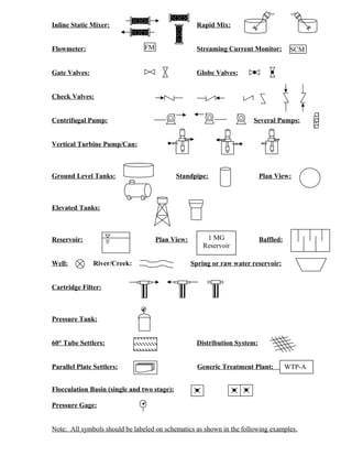
1. Inline Static Mixer: Rapid Mix:
Flowmeter: Streaming Current Monitor:
Gate Valves: Globe Valves:
Check Valves:
Centrifugal Pump: Several Pumps:
Vertical Turbine Pump/Can:
Ground Level Tanks: Standpipe: Plan View:
Elevated Tanks:
Reservoir: Plan View: Baffled:
Well: River/Creek: Spring or raw water reservoir:
Cartridge Filter:
Pressure Tank:
60° Tube Settlers: Distribution System:
Parallel Plate Settlers: Generic Treatment Plant:
Flocculation Basin (single and two stage):
Pressure Gage:
Note: All symbols should be labeled on schematics as shown in the following examples.
FM SCM
1 MG
Reservoir
WTP-A
2. Water System Schematic
Well #10
Pringle Spring
Lafayette Springs Area
Well #3
(disconnected)
Blue Bird Spring
Well #8
Well #1
500,000 gallon
reservoir
Well #2
City Park Well
(Chlorination/
pressure sand
filtration for Fe/Mn
removal)
● EP C
● EP D
Dayton/Lafayette
Wellfield
● EP A
Well #7
(emergency)
● EP B
pH
Cl
● Flow meter
Sodium hypochlorite
Soda ash
Test
building
3. Water System Schematic
Settling
Basin
NALCO 8105
Flocculation
Filter
1,900 gallon
Clearwell
Two 175-gpm pumps
Sodium Hypochlorite
42,000
gallon
Reservoir
Distribution
Bypass Line with
valves (normally
closed)
(both springs are captured as surface water)
SRC-AA
SRC-AB SRC-AC
Graham
Creek Spring #1 Spring #2
4. Construction of Kegbine Springs #1 and #2
(Similar for Both)
Concrete casing with collection holes at the bottom
Topsoil
Plastic Barrier
Rock
To Upper Collection Box
Construction of Big La Toutena Mary Spring
Concrete structure with metal roof, bolted hatch. Water flows up
through rock in the bottom.
Topsoil
Rock
To Main Collection Box
Construction of Little La Toutena Mary Spring
Subsurface perforated piping under plastic barrier captures water
Topsoil
Plastic Barrier
Rock
To Main Collection Box
5. From pump station
to the water
treatment plant 60-inch screening
pump station manhole South Yamhill River
wet well 71-in x 47-in corrugated
metal pipe diversion
KMnO4
(taste&odor)
Hypochlorite
Res #1
0.25 MG
Filter
TubeSettlers
Flowmeter
Splitter
Box
67.5% flow
Intake Pump
Station
Inline
mixer
(PotentialSodaAsh)
Alum
SodaAsh
Plant #2 – 0.8 MGD
(1990)
32.5% flow
Plant #1 – 0.5 MGD
(1982)
NTU
NTU
NTU
F-
SouthYamhillRiver
VariableSpeed
flocbasins
FM
FM
6. Stoney Mt. Spring
Sources
(Approx. 9 miles
from Res #2)
Res #2
0.5 MG
Res #3
1.83 MG
Res #4
“Ballston Reservoir”
1.5 MG
S. Yamhill River
14” Main
9 Services
14” Bridge St Main
EP-A
EP-B
WTP-B
SRC-AA
WTP-A
Res #1
0.317 MG
Clearwell
SRC-BA
SRC-BB
SRC-BC
SRC-BD
SRC-BE
7. Rawwatersampletap
Hypochlorite
DownflowFilter
Flowmeter
(Total flow
and gpm)
NTU (1720D)
Intake Pump
Station
Static
mixer
SurfaceScatter6(NTU)
SodaAsh
Train #1
0.288 MGD
(1990)
Train #2
0.288 MGD
NTU
NTU(1720E)
NTU
UpflowClarifier
flocbasins
FM
Static
mixer
PAC
(PASS-C)
NTU (1720D)
26,785-gal
Clearwell
(c. 2002)
20 Hp, 200 gpm
pumps
CL2, pH, Temp
To Distribution
FM
11,725-gal
Clearwell
(c. 1973)
SCM
SCM