Downloaded 100 times
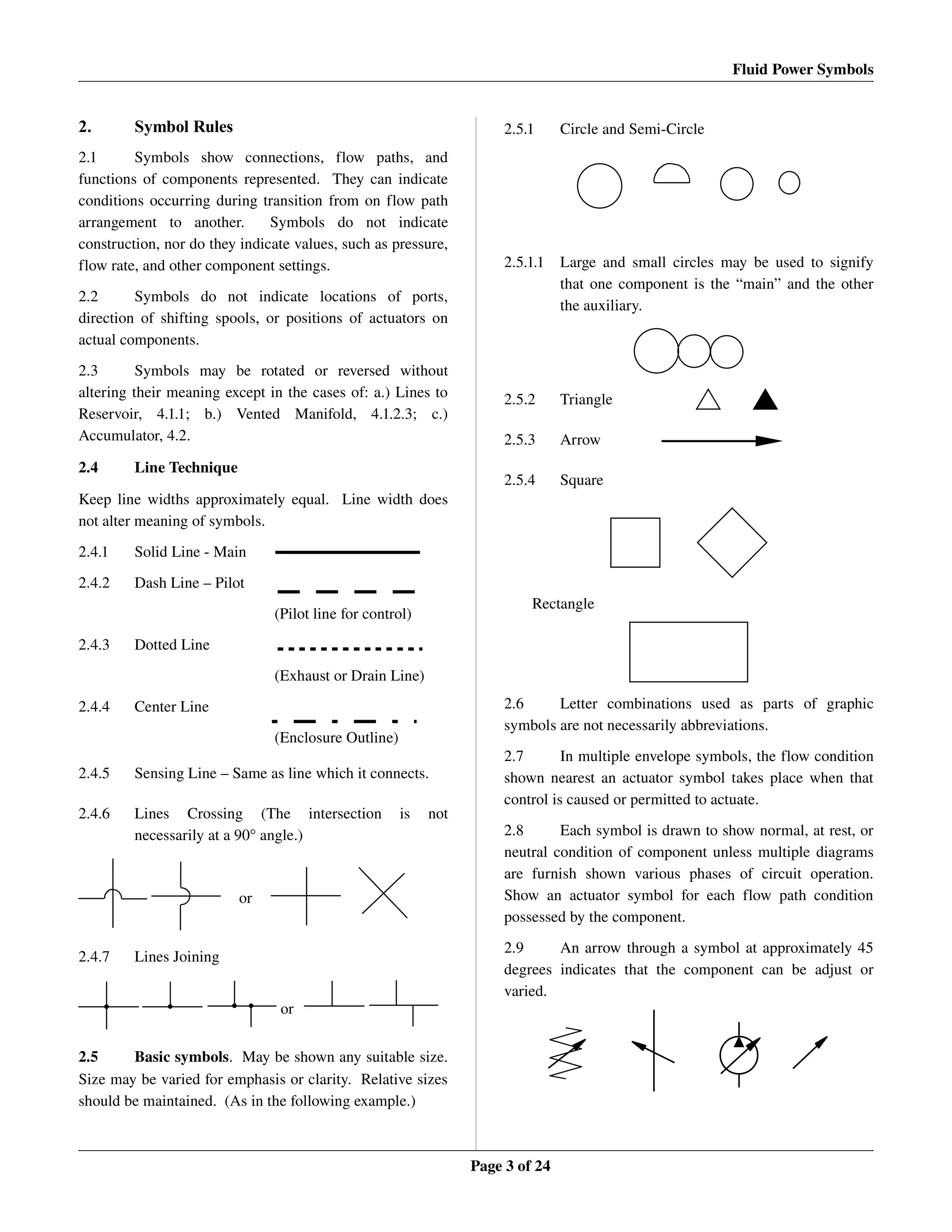
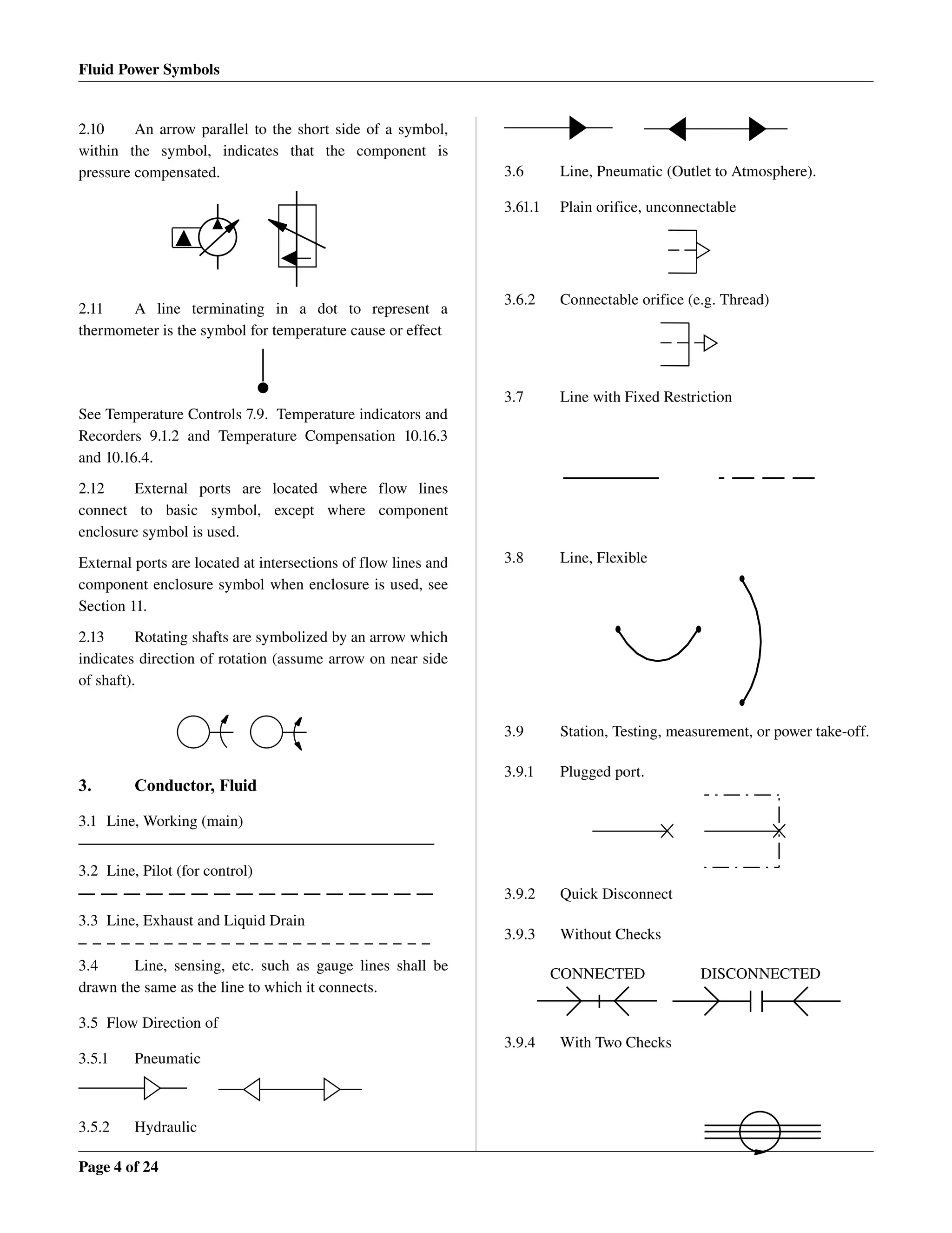
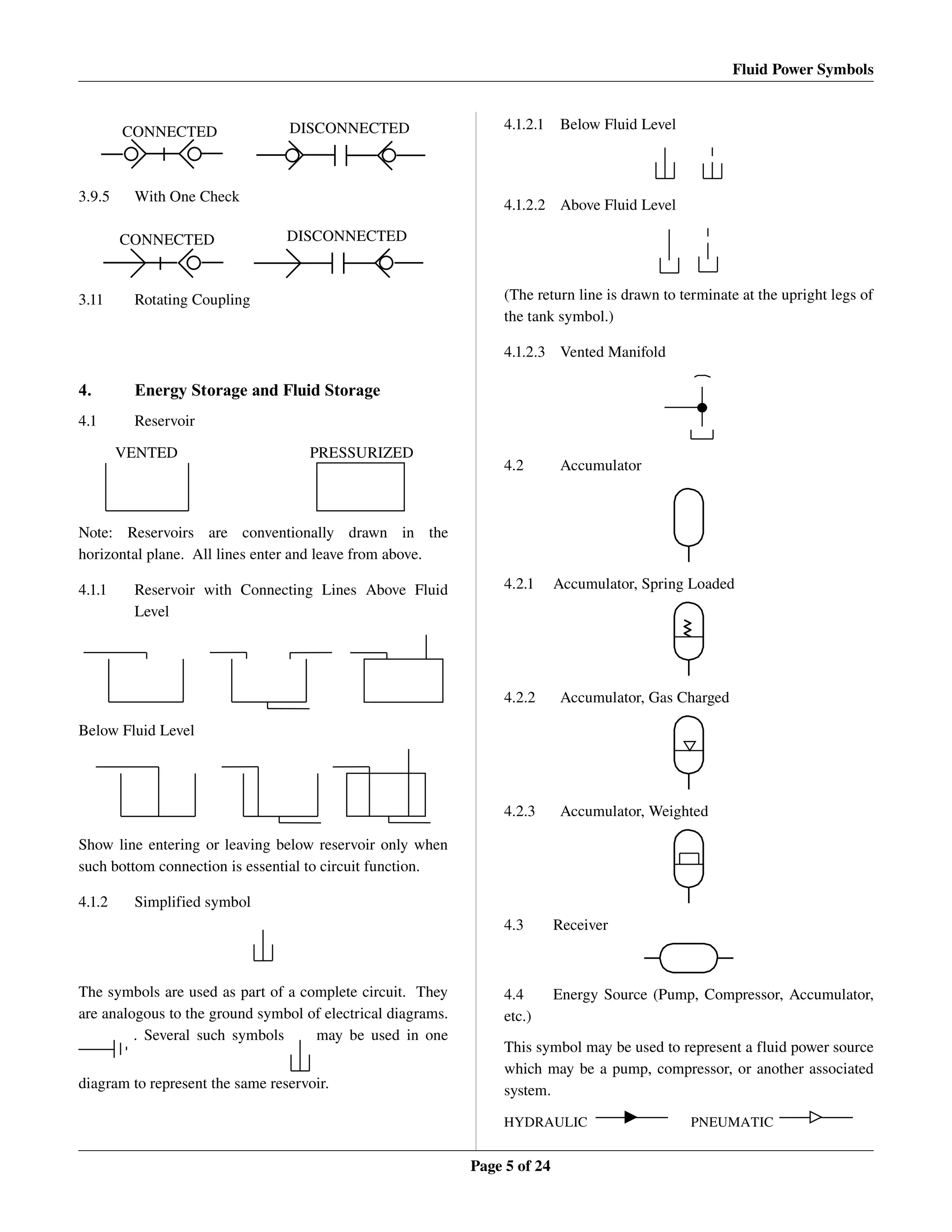
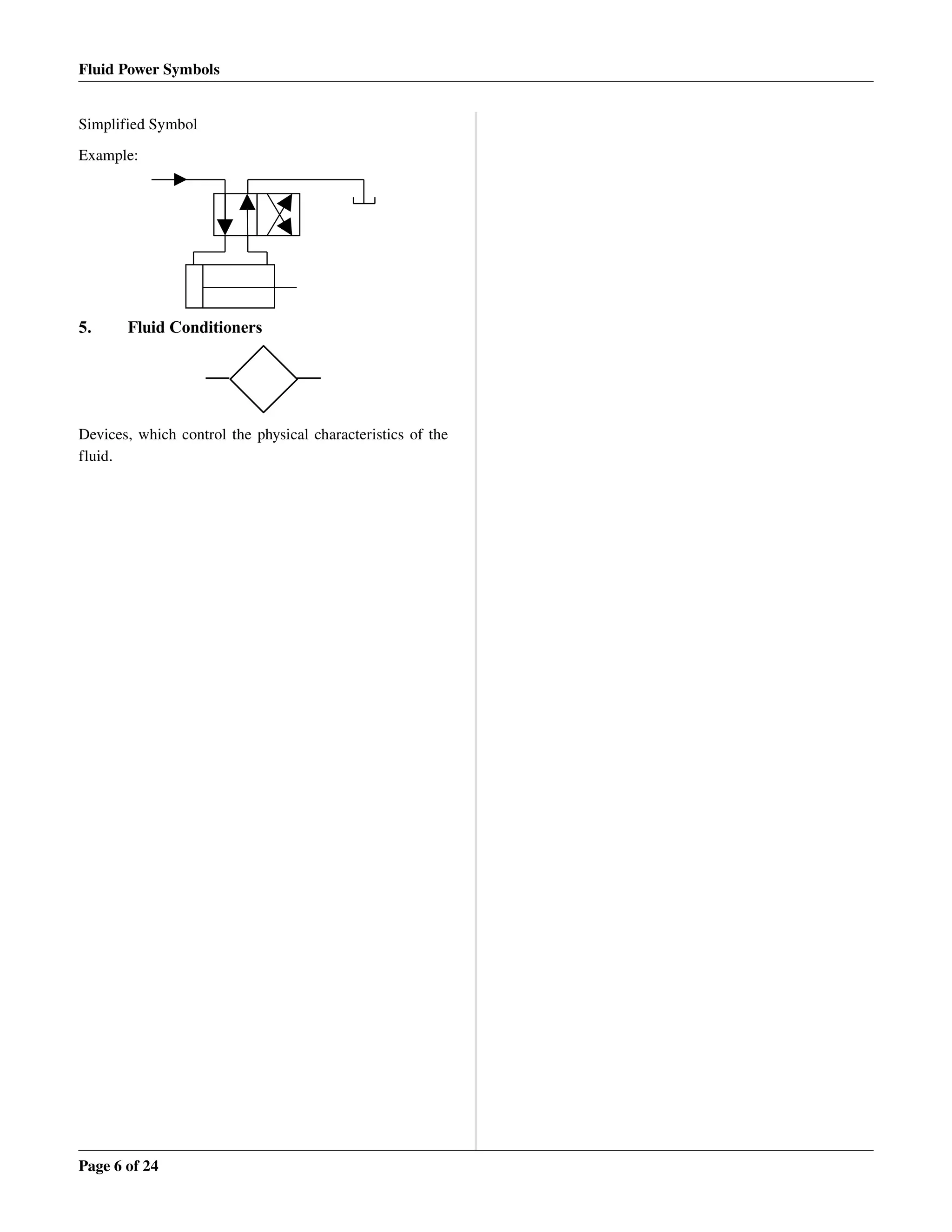
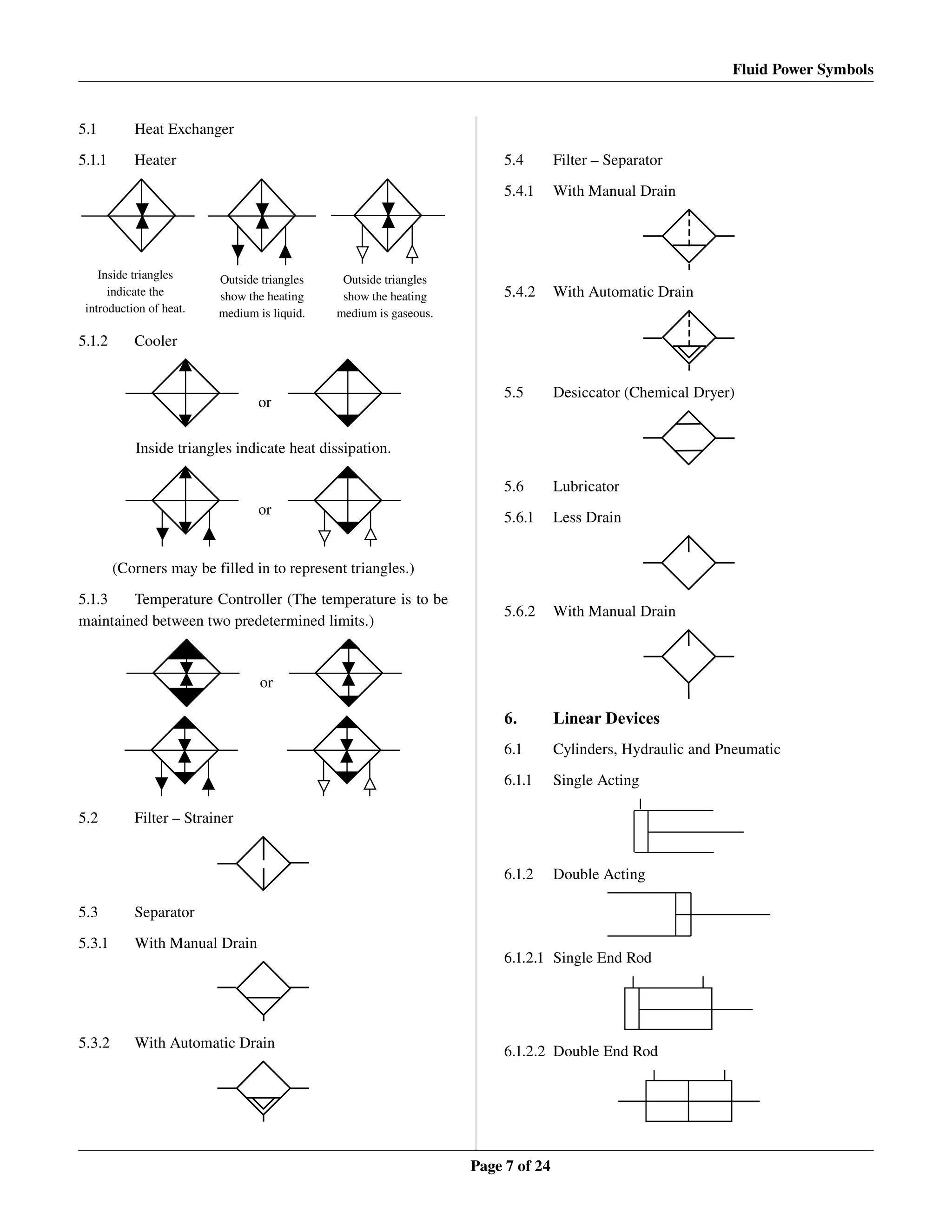
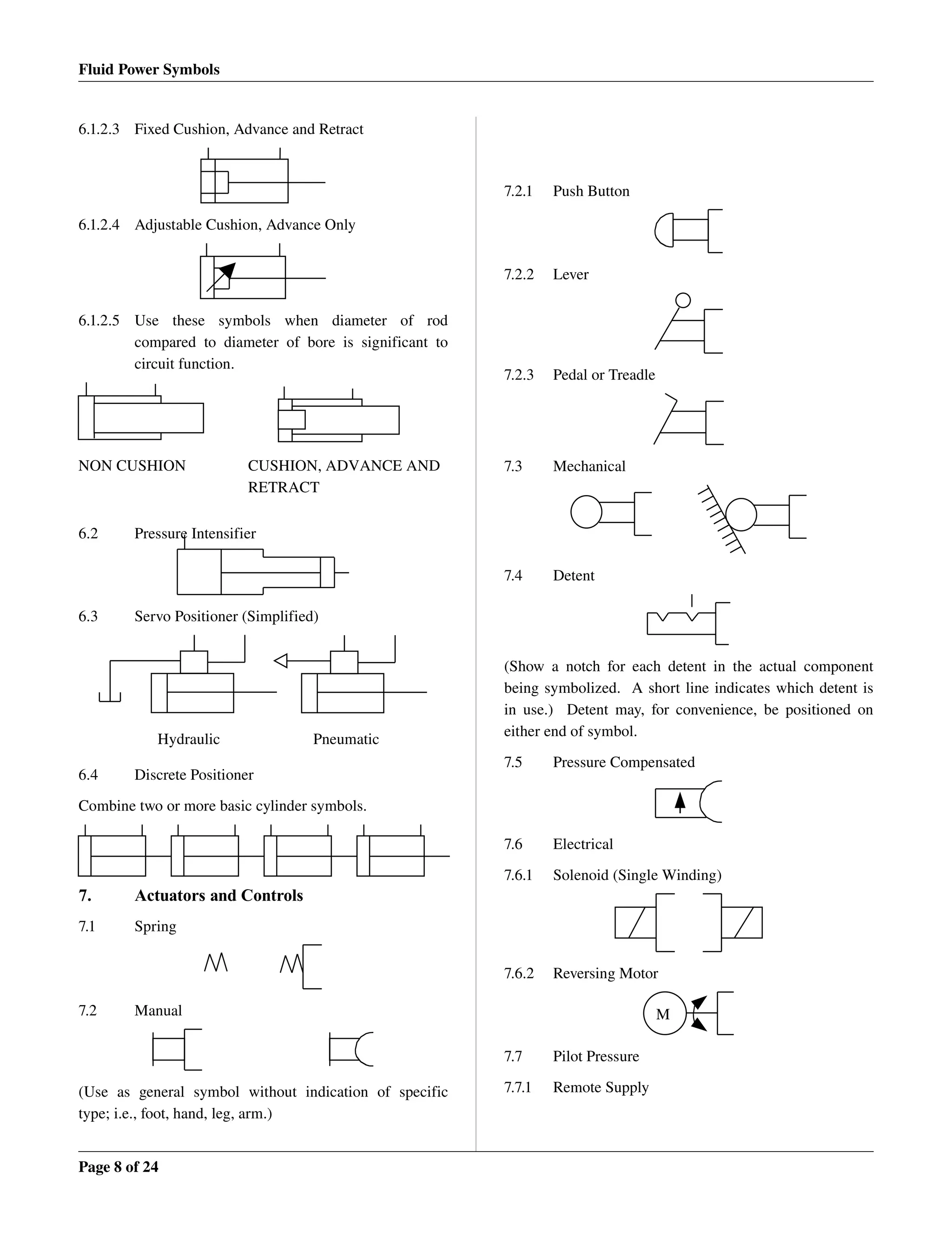

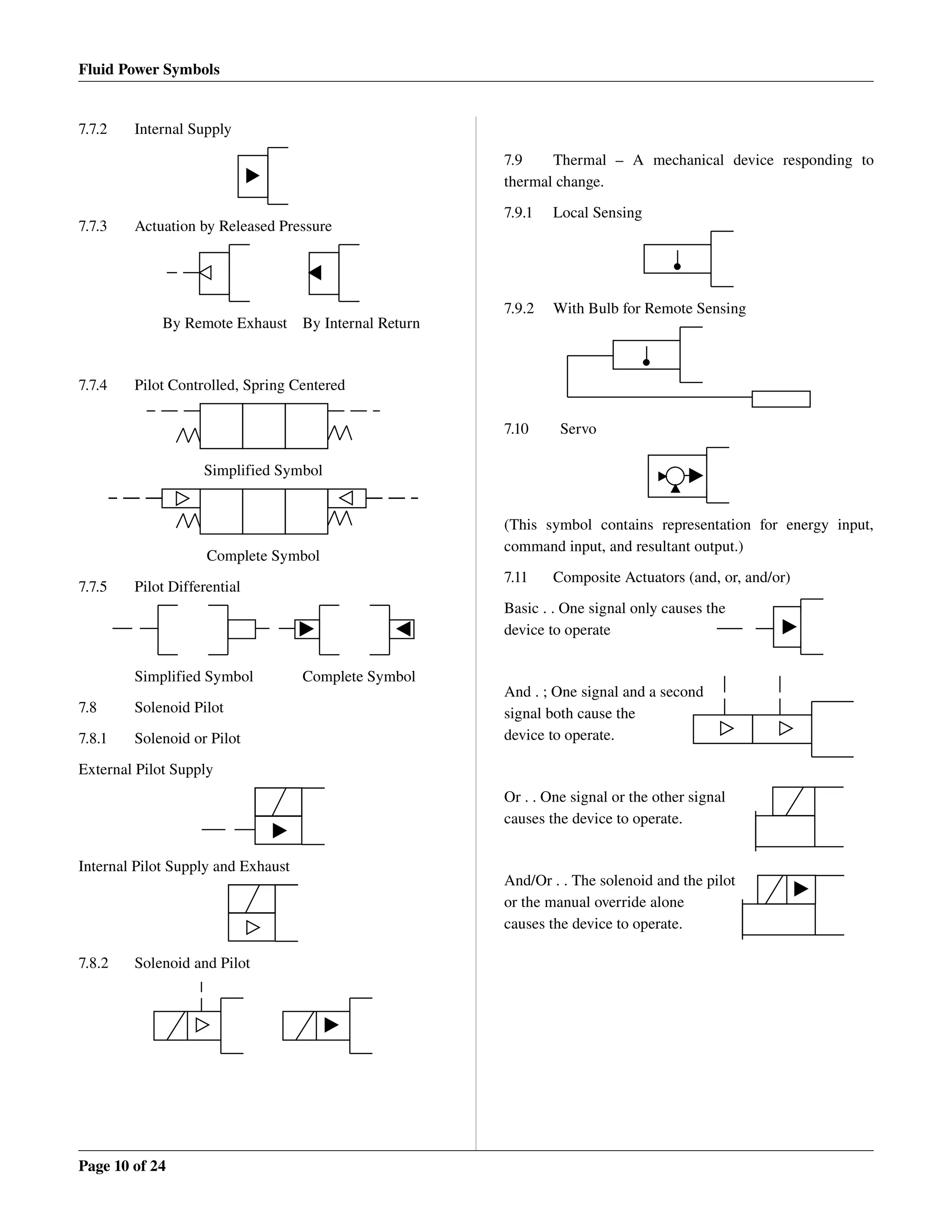
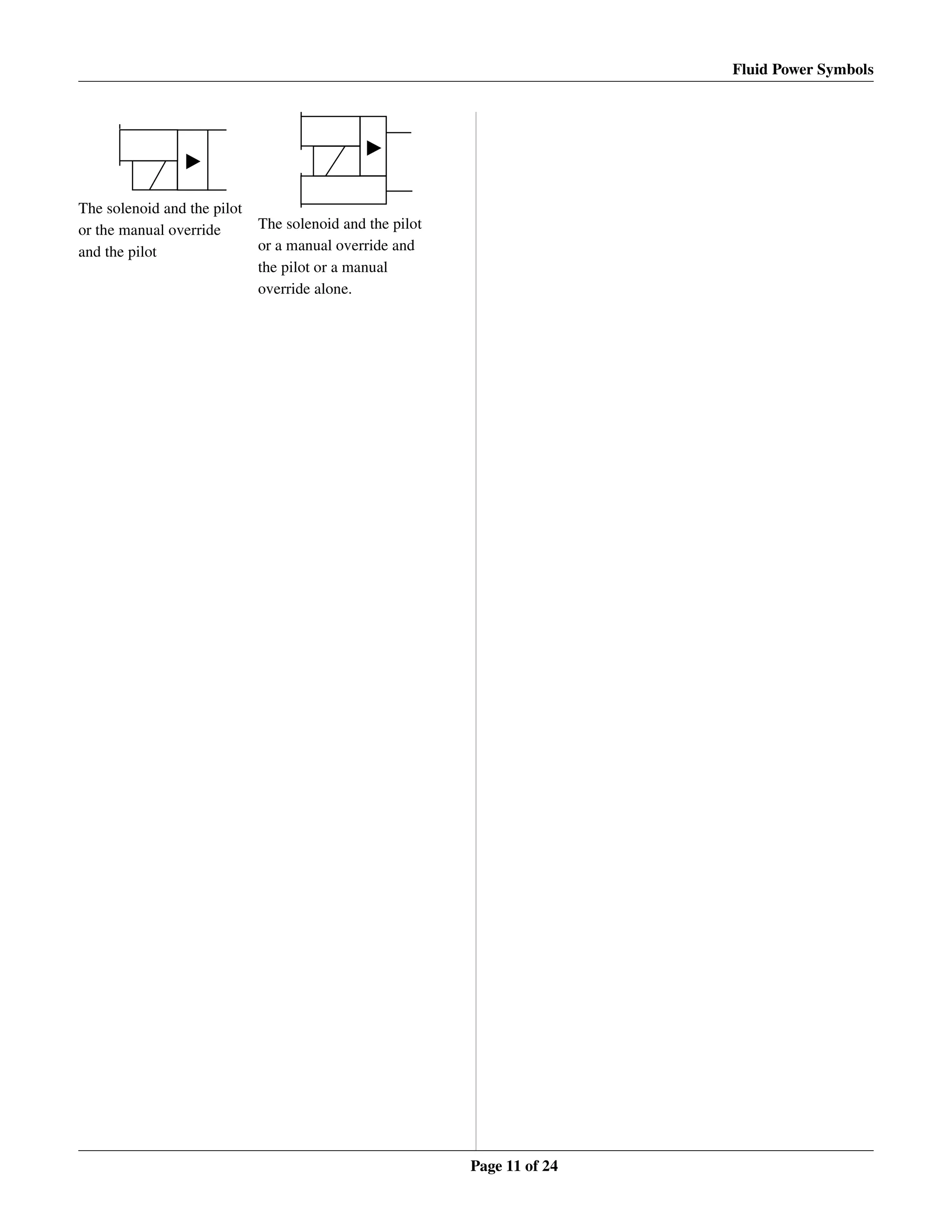
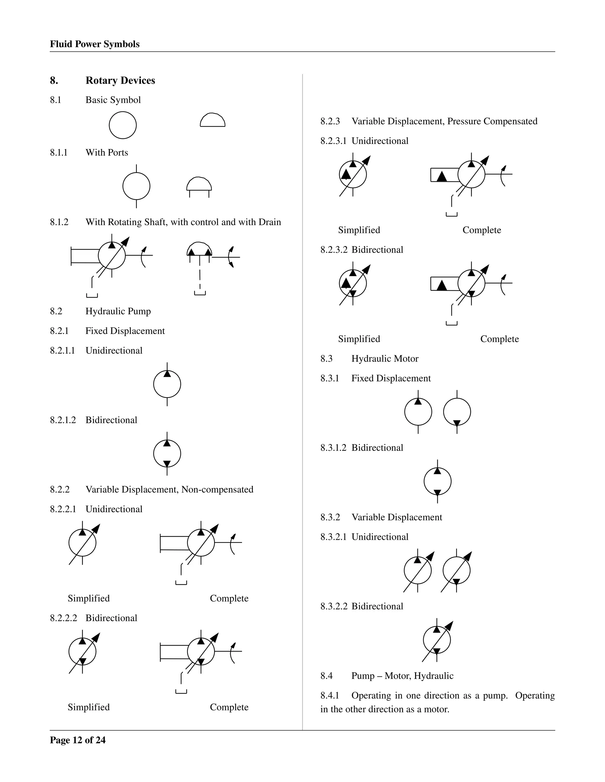
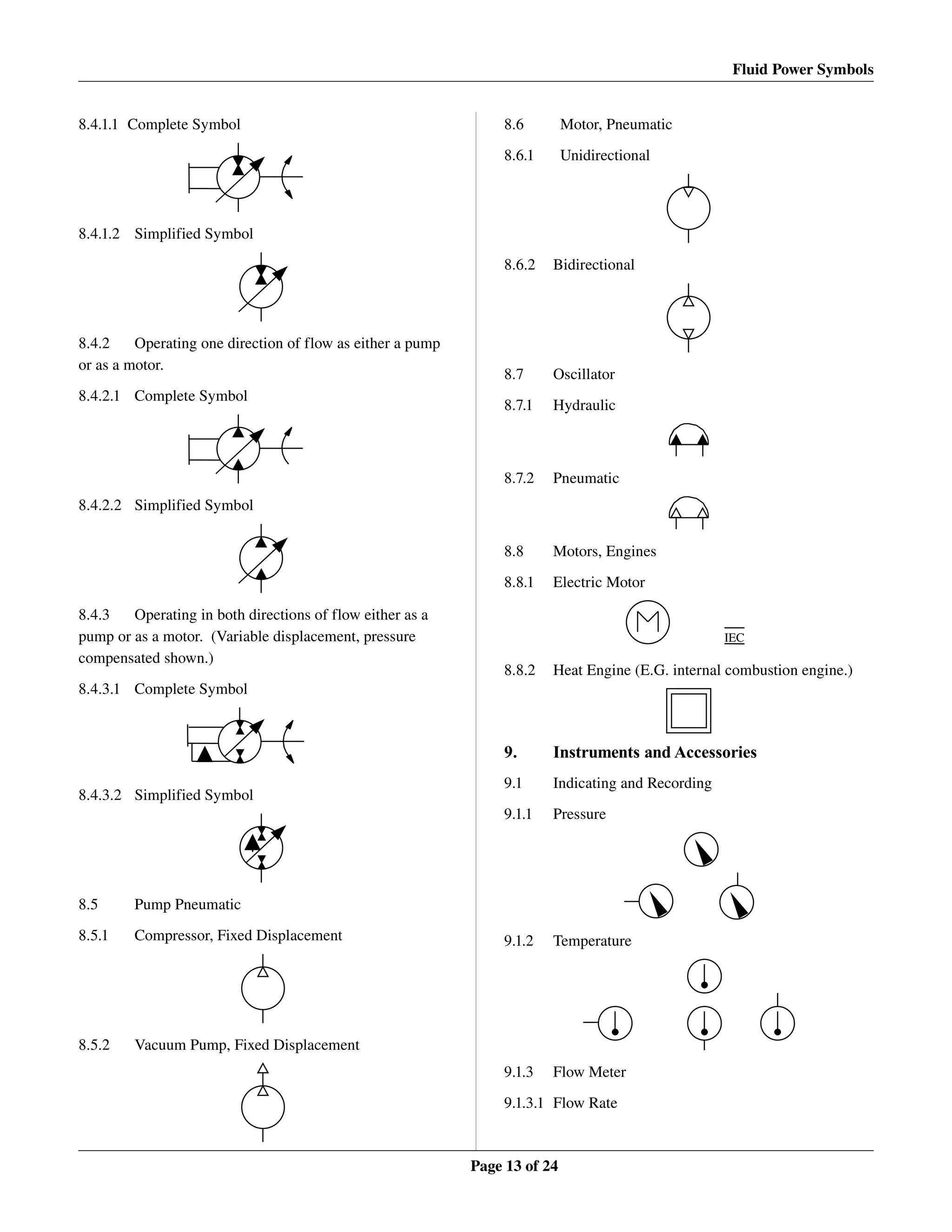

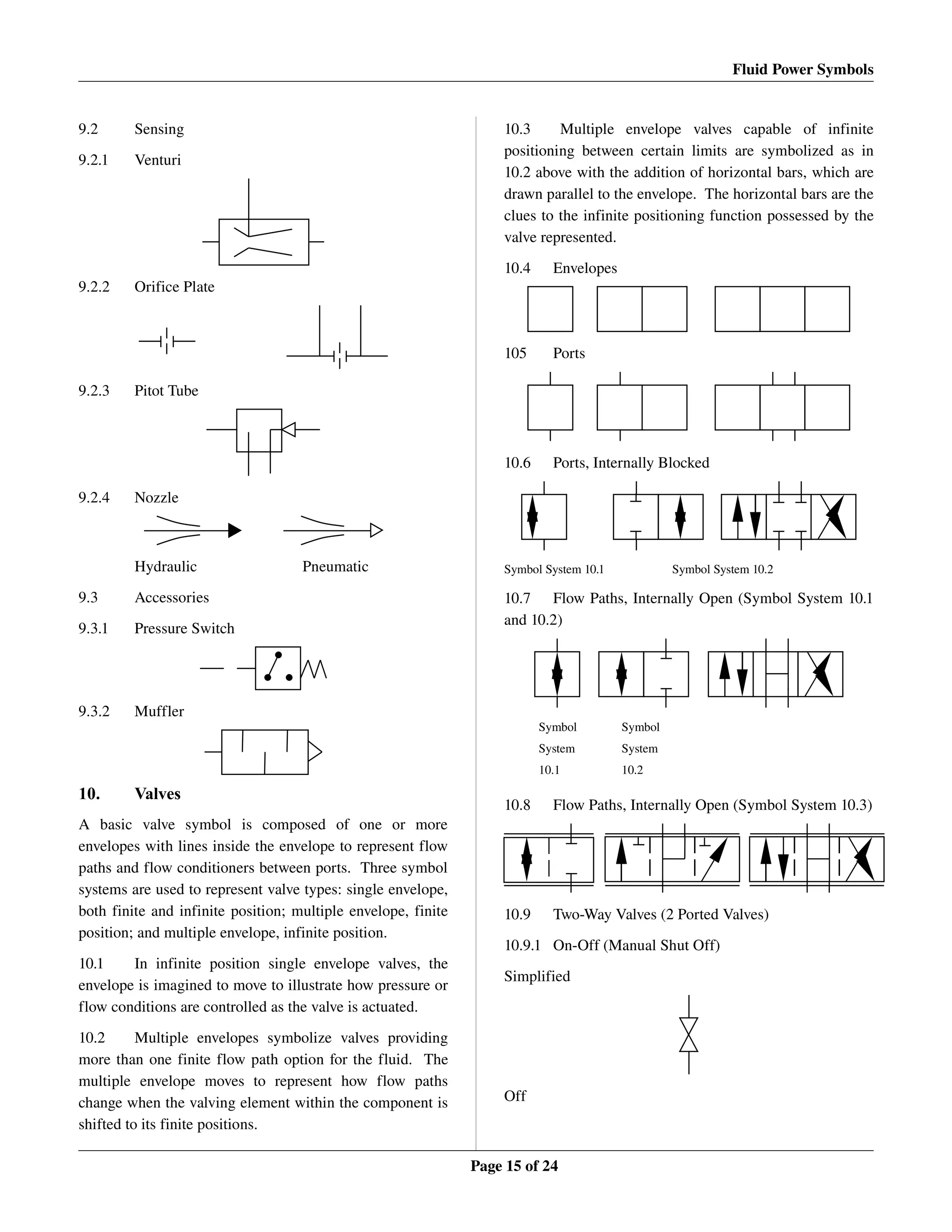
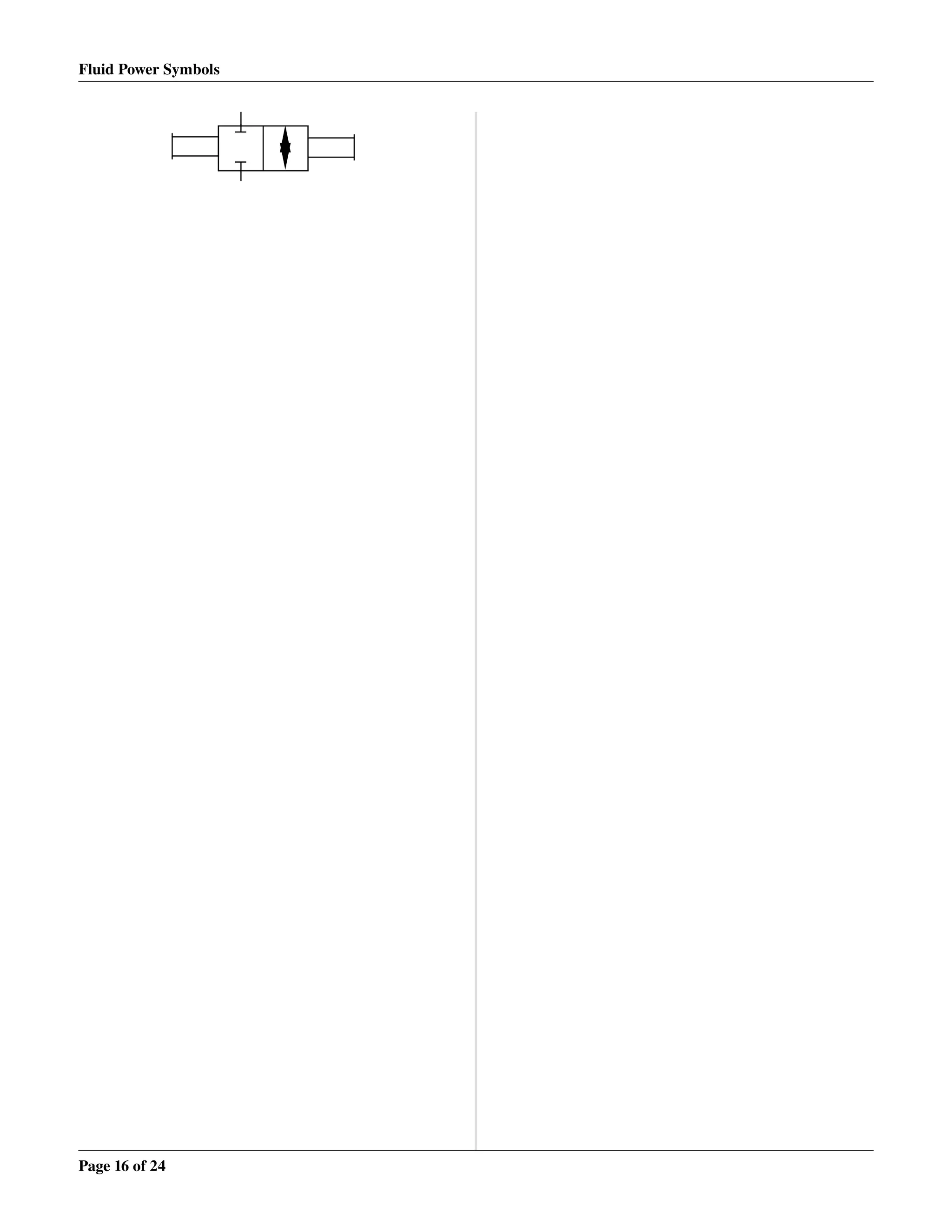
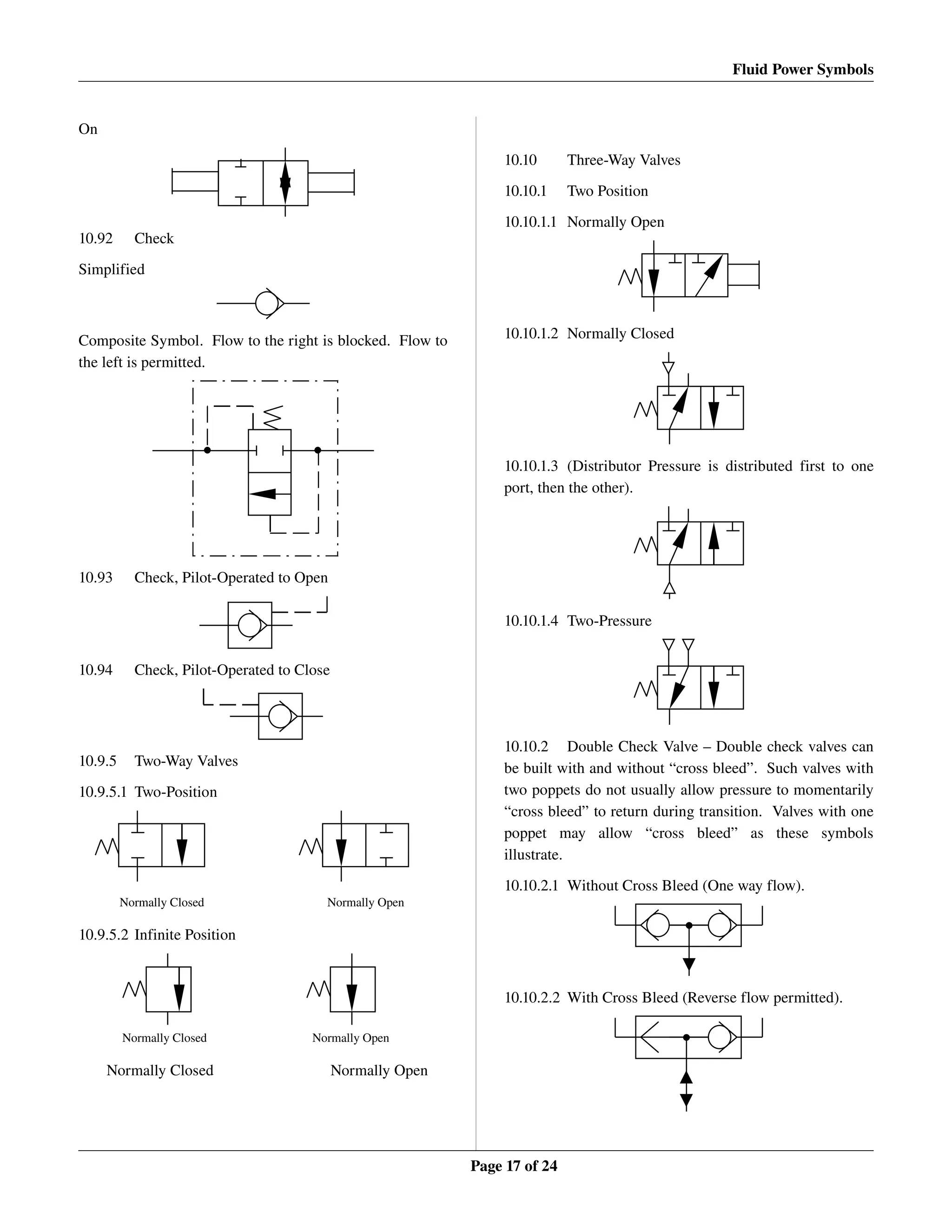
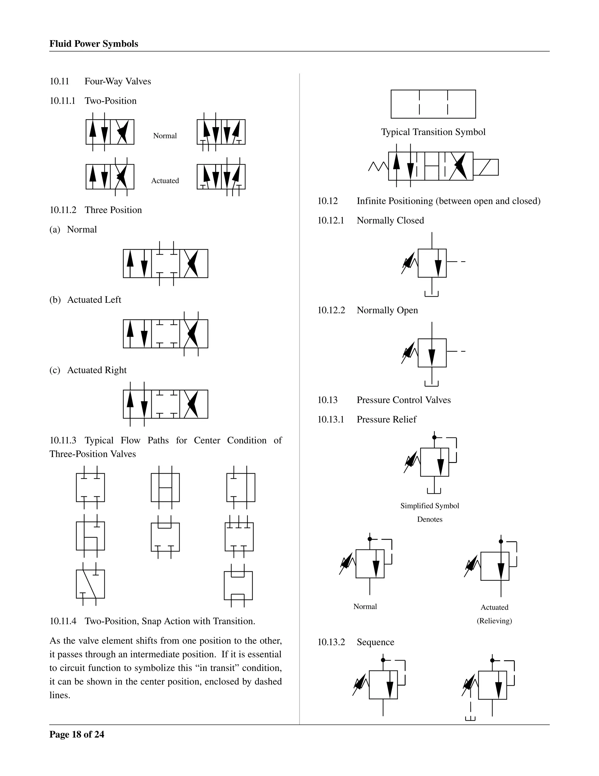
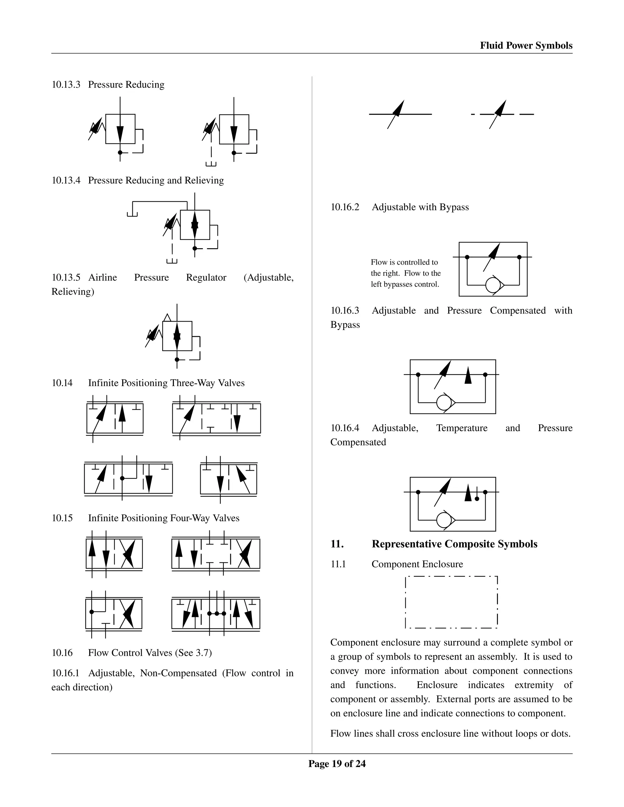
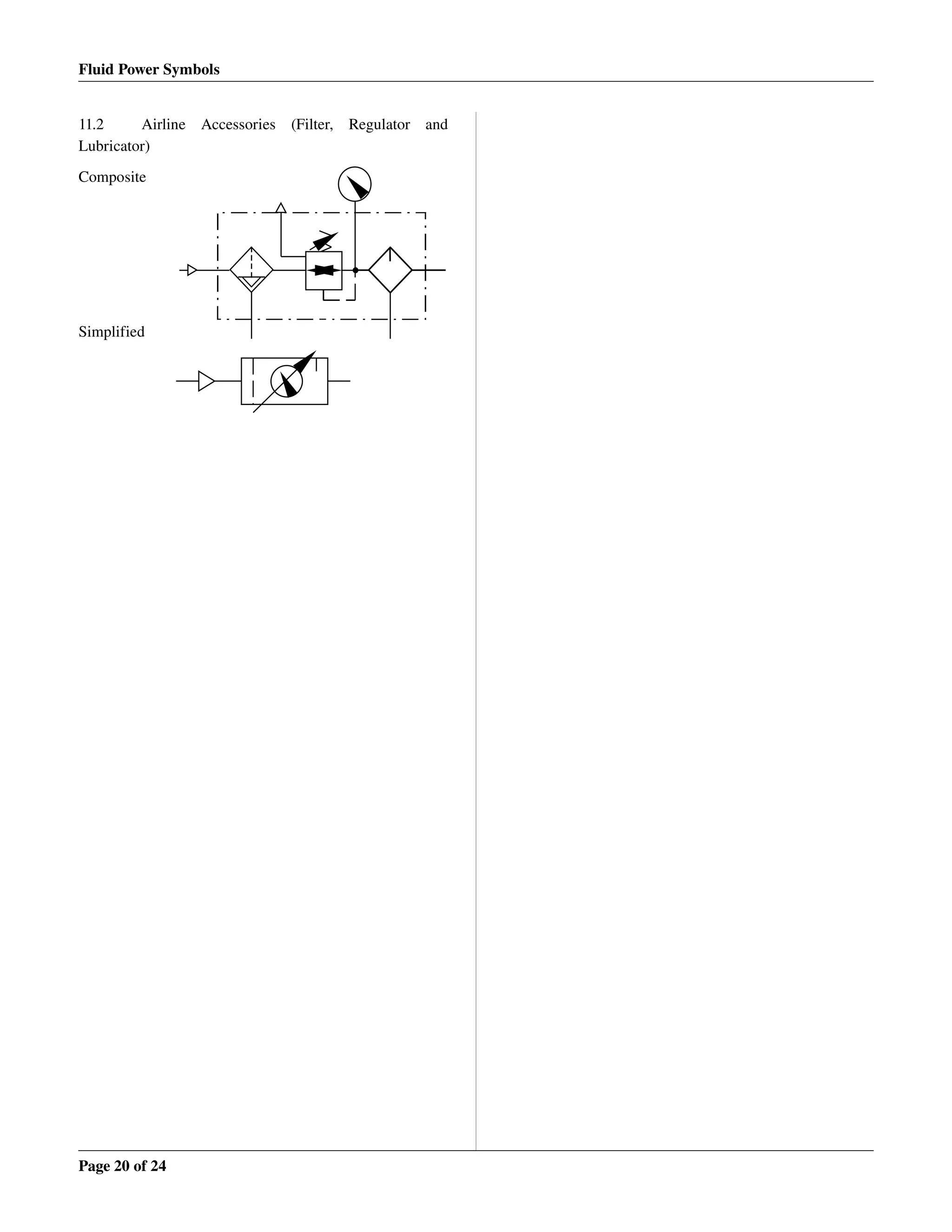
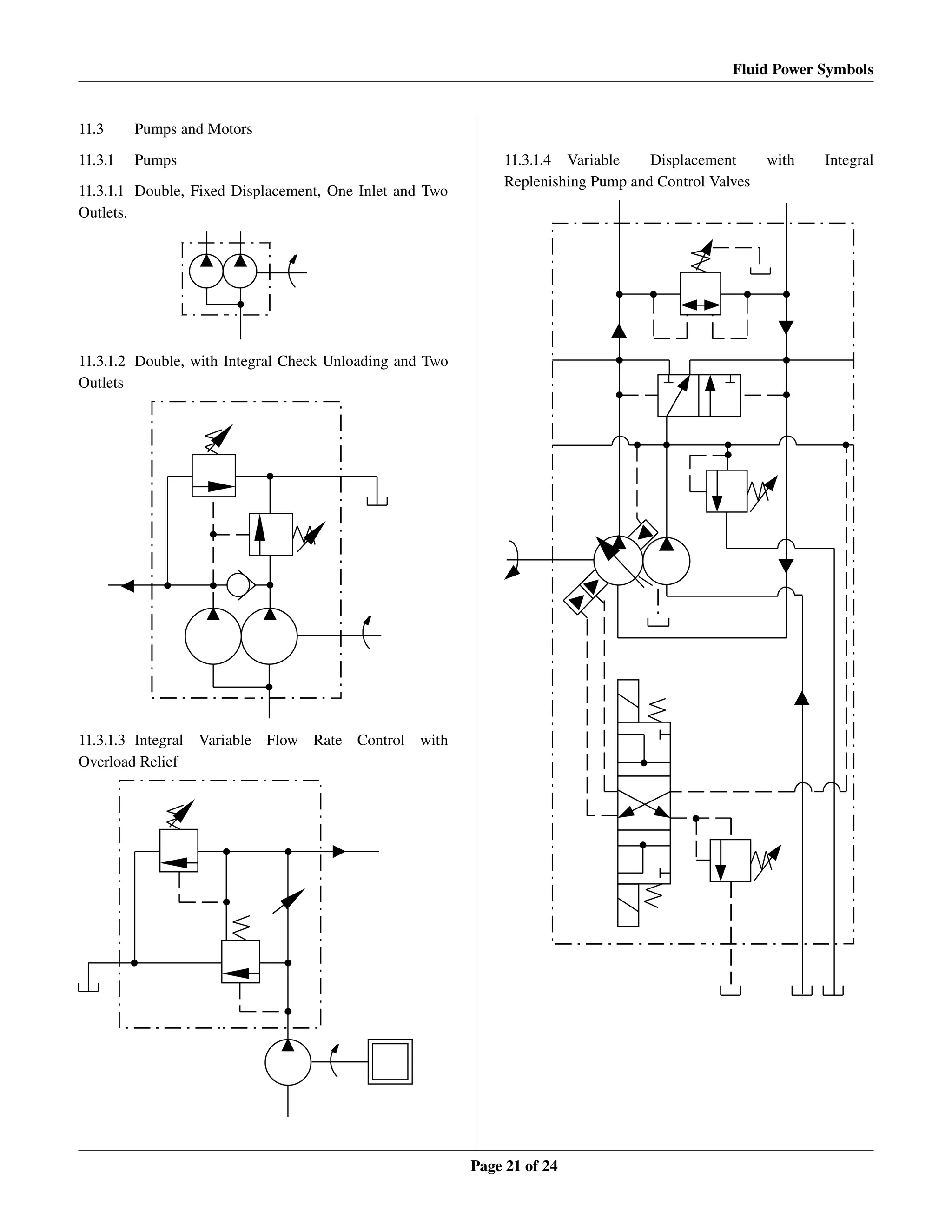
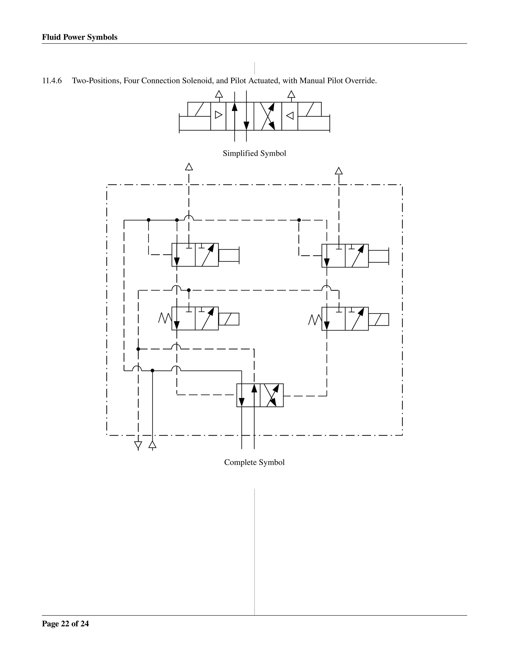

This document provides standards for fluid power graphic symbols used in circuit diagrams for fluid power systems. It discusses the types of symbols commonly used, including pictorial, cutaway, and graphic symbols. Graphic symbols are preferred as they emphasize component function, are simple to draw, and can promote universal understanding. The document then describes rules for the symbols, including how to represent lines, basic shapes, flow direction, reservoirs, accumulators, filters, cylinders, actuators and more. It provides the specific graphic symbol for numerous fluid power components. The purpose is to standardize symbols to simplify the design, analysis and understanding of fluid power circuits.


![ANPARA THERMAL POWER STATION[1] sangam.pdf](https://cdn.slidesharecdn.com/ss_thumbnails/anparathermalpowerstation1sangam-251121115219-9261cde4-thumbnail.jpg?width=640&height=640&fit=bounds)


