SlideShare a Scribd company logo
1 of 67
CEE 213—Deformable Solids
© Keith D. Hjelmstad 2014
CP 2
Properties of polygonal plane areas
Keith D. Hjelmstad
School for Sustainable Engineering and the Built Environment
Ira A. Fulton Schools of Engineering
Arizona State University
CEE 213—Deformable Solids
© Keith D. Hjelmstad 2014
CP 2—Properties of Areas
The properties of cross sections
The properties of cross sections. In the study of beams
(including the axial bar and torsion) it becomes evident
that much of the behavior is dictated by the properties of
the cross sectional geometry. In fact, the resistance to
deformation is always a function of the distribution of
material in a cross section. For the axial bar the cross
sectional area is key; for torsion the polar moment of
inertia shows up; for flexure the moment of inertia about
the axis of bending is an important property. These
properties are essential to determining the deformation
under load.
Most of the classical “tricks of the trade” that can be used
in service of the computation of geometric properties
amount to making use of the properties of simple
geometric pieces (often rectangles) to build up the overall
cross sectional properties. What we show in this set of
notes is that it is possible to derive the integrals needed to
compute the cross sectional properties for a general
triangle and then use that basic foundation to create a
method to compute the cross sectional properties of any
closed polygonal region. This approach is based on two
key observations: (1) all integrals can be divided into
pieces and (2) it is possible to add in an integral that is
not in the physical region as long as you subtract it right
back out.
Cross Section
x
Longitudinal Axis
Cross Section
y
z
CEE 213—Deformable Solids
© Keith D. Hjelmstad 2014
A
CP 2—Properties of Areas
The key cross sectional properties
The key cross sectional properties. Consider the
general cross section defined at left. We establish a (y, z)
coordinate system with origin O, and imagine another
coordinate system (x, h) passing through the centroid C.
For beam theory we need to compute area and moment
of inertia (about the centroid). To compute the moment of
inertia we need the location of the centroid.
The area is simply defined as the sum of the infinitesimal
areas that make up the cross section:
y
z
x
h
c
ρ
dA
2
e
3
e
r
O
C
A
The centroid of an area is defined as follows:
1
A
dA
A
In other words, it is the constant vector c that is the
average over the area of the position r of the infinitesimal
areas. Finally, the moment of inertia (tensor) is defined as
Where the vector r is the distance from the centroid C to
the infinitesimal area of integration.
2
1 1 1 2
1 2 2
2 1 2 2
T
v v v v
v v
v v v v
v v v v
The tensor (or outer) product of vectors
CEE 213—Deformable Solids
© Keith D. Hjelmstad 2014
CP 2—Properties of Areas
The moment of inertia tensor
The moment of inertia tensor. The problem with
computing J is that it is defined in terms of the centroidal
coordinate system. We can compute it in the regular
coordinates noting that (by vector addition)
y
z
x
h
c
ρ
dA
2
e
3
e
r
O
C
A
A
A
A A A A
A
A
dA
dA
dA
dA dA dA dA
dA A A A
dA A
J ρ ρ
r c r c
r r c r r c c c
r r c r r c c c
r r c c c c c c
r r c c
2
2
T
y
y z
z
y y z
y z z
r r r r
1
1 2
2
2
1 1 2
2
1 2 2
T
c
c c
c
c c c
c c c
c c c c
Thus, we can compute
Therefore, we can compute the moment of inertia tensor
in the original coordinate system as
A
We need the centroidal distance c, and we need to figure
CEE 213—Deformable Solids
© Keith D. Hjelmstad 2014
CP 2—Properties of Areas
The general triangular region
The general trianglular region. We can specialize the
notion of our cross sectional properties to a general
triangular region (shown at left). We will need to get
specific about how to do the integrals over this region.
Once we have found the results, we can use them as a
basic building block in an algorithm to compute the three
basic properties of any polygonal cross section (and, by
taking points close together we can approximate cross
sections with curved edges, too).
We will construct our concept of the triangle from the
position vectors of the two vertices i and j (which will lie
on an edge of the polygon later). These vectors are xi and
xj. From these vectors we can compute h, b, and the unit
vectors n and m (as shown in the box at left).
y
z
c
2
e
3
e
i
j
h
b
O
y
z
j
xix
j i
y
z
n
m
i
j
h
b
O O
The basic triangle
i
j i
h
b
x
n
x x
m
i
j i
h
b
x
x x
All of these key quantities can be
computed from the vectors xi and xj
CEE 213—Deformable Solids
© Keith D. Hjelmstad 2014
1
1
1 2 3 3 2
sin
sin
dA d d
dA d d
d d
n m n m
x h
h x
x
e n m
n m e
n m e
CP 2—Properties of Areas
Integration over the triangle Integration over the triangular
region. It will
be convenient to set up the area integration in the
coordinate system n and m (which happens not to
be rectangular).
dAdxn
dhm
( )
0 0
0 0
( ) sin ( )
sin ( )
h w
A
b
h
h
dA d d
d d
x
x
dA
x n
h m
( )
b
w
h
The variables of integration are x (measures
distance in n direction) and h (measures distance
in m direction), which are in the range
Note how the limits of integration are done in
the box at right.
Thus, the element of integration is
And the integration over the area is done as
CEE 213—Deformable Solids
© Keith D. Hjelmstad 2014
0 0
00
0
21
2
0
1
2
sin
sin
sin
sin
sin
A
b
h
h
bh
h
h
h
A dA
d d
d
b
d
h
b
h
b h
x
x
CP 2—Properties of Areas
Area of the general triangle
For beam theory we need to compute
area, centroidal location, and moment
of inertia (about the centroid): 1
2
dA
x n
h m
( )
b
w
h
Area of the general triangle. We can compute area of
the triangle as follows:
Note how “one half base times height” still seems to be
things: (1) that the triangle is not a right triangle and (2)
if it turns out to be negative then the area is “negative.”
The area of the general triangle is
CEE 213—Deformable Solids
© Keith D. Hjelmstad 2014
0 0
21
2
00
2
2 21
2
0
2
3 31 1
3 6
0
2 21 1
3 6
2 1
3 3
sin
sin
sin
sin
sin
A
b
h
h
b
h
h
h
h
dA
d d
d
b b
d
h h
b b
h h
b h b h
A h b
x
x
p r
n m
n m
n m
n m
n m
n m
A
CP 2—Properties of Areas
The centroid of the triangle
We will sum the contributions for
each triangle so we will not compute
c (the location of the centroid) for the
cross section until we add up all of
the p contributions.
dA
x n
h m
( )
b
w
h
The centroid of the triangle. We can compute the
integral of r over the triangle as follows:
Note that p is one third of the distance from the edges,
but adjusted by the general area A and measured in the
directions n and m. The location of the centroid of the
general triangle is
CEE 213—Deformable Solids
© Keith D. Hjelmstad 2014
0 0
2 2
0 0
2 2 31 1
2 3
00
2 3
3 3 31 1
2 3
0
2
4 4 41 1 1
4 8 12
sin
sin
sin
sin
sin
b
h
h
A
b
h
h
b
h
h
h
dA d d
d d
d
b b b
d
h h h
b b
h h
x
x
x
r r n m n m
A B C
A B C
A B C
A B
3
0
3 2 2 31 1 1
4 8 12
2 21 1 1
2 4 6
sin
h
b
h
b h b h b h
A h bh b
C
A B C
A B C
A n n
B n m m n
C m m
A
B C
It is convenient to define tensors
CP 2—Properties of Areas
outer product of r with itself for the triangular region as
follows:
Hence, we have the following result (which we will
eventually use to compute the moment of inertia)
These tensors are constant over the
triangle and therefore can be pulled out of
the integral.
Note that we will not compute the actual
moment of inertia about the centroid at
this point because we plan to add together
multiple pieces to construct the moment
of inertia for polygonal regions. So we
will simply compute (and accumulate) the
integrals of the outer product.
The vector r to the elemental point of
integration is
CEE 213—Deformable Solids
© Keith D. Hjelmstad 2014
CP 2—Properties of Areas
Positive and negative regions
We can compute integrals over a cross section by considering
positive and negative areas. In regions
where there are both, they cancel each other out. The I-beam,
for example, can be constructed from the
large (positive) rectangle and the two smaller (negative)
rectangles.
We will use this general idea to accumulate the contributions of
the triangles that define the sides of the
and if it is less than zero then the area will be
negative. For any region that has both a positive and negative
contribution the net effect (in all of our
integrals) will be zero. Hence, this is a good way to lay out the
calculation.
A A A
A A
w dA w dA w dA
w dA w dA
(-) (0)(+) + =
Zero
region
Actual cross
section
Positive
region
Negative
region
(+) (-) (-)
CEE 213—Deformable Solids
© Keith D. Hjelmstad 2014
CP 2—Properties of Areas
Accumulation of properties
Consider the cross section shown at
right. Taking the points sequentially
we see the contributions of four
then the area is negative (red),
otherwise it is positive (blue).
Notice how the areas outside the
cross section get exactly one positive
and one negative contribution. In the
end, only the blue region remains.
1
2
3
4
n
m
n
m
n
m
n
m
The Cross Section Triangle 1 (side 1-2)
Triangle 2 (side 2-3) Triangle 3 (side 3-4) Triangle 4 (side 4-1)
1
2
2
3 3
4
1
4
O O
O O O
CEE 213—Deformable Solids
© Keith D. Hjelmstad 2014
CP 2—Properties of Areas
Positive regions and negative regions
Positive regions and negative regions. The power of the
approach we are taking is the ability to distinguish
between positive regions and negative regions. When we
use the general triangle as the building block for
computing integrals over a polygonal shape we must be
able to assign a positive or negative value to each piece
in accord with the need to either add that portion to the
of this issue. Recall the definition
According to the definition of cross product, the angle is
clockwise from the vector n to the vector m. You can see
how this plays out in the two examples below (the
triangles for sides 1-2 and 2-3 for our example).
The sine function is positive in the first and
second quadrant and negative in the third and
fourth, and this gives the integrals their
algebraic sign. Also, as the vectors tend to point
along the same line the magnitude gets smaller
(to reflect that the region of the triangle gets
smaller).
n
m
n
m
n
m
2
e
3
e
CEE 213—Deformable Solids
© Keith D. Hjelmstad 2014
CP 2—Properties of Areas
Algorithm
1 1
2 2
1 1
1. Store coordinates of vertices in array
2. Initialize properties 0, ,
3. Loop over the sides, 1:
a. Compute the unit vectors and from
b. Compute
N N
i i
x y
x y
x y
x y
A
i N
x
x
p 0 R 0
n m x
1
sin
c. Compute the triangle contributions
, , and
d. Add the contributions to the whole
, ,
4. Finish the computation of and
/ ,
5. Com
i i i
i i i
i i i
A A A
i i i
A dA dA dA
A A A
A A
n m e
p r R r r
p p p R R R
c J
c p J R c c
pute principal values of
6. Print and plot results
J
1
2
3
4
The Cross SectionO
Algorithm. We can organize the computation as follows:
The process can be put into a program with
the steps outlined at right. In the loop we carry
out the computations associated with the
triangle whose edge is defined by the current
vertices. We then accumulate those into sums
for each of the properties (i.e., we are adding
up all of the contributions of all triangles).
Once the loop is complete we can finish the
computations of c and J, find the principal
values, and print and/or plot the results.
CEE 213—Deformable Solids
© Keith D. Hjelmstad 2014
CP 2—Properties of Areas
Principal values of J
Principal values of J. When the off-diagonal elements of
the tensor J are not zero that implies that the Jyy and Jzz
values are not the maximum or minimum moments of
inertia of the cross section.
The way we computed J had the first step of laying down
a coordinate system (y, z). We found the location of the
centroid C and that allowed us to nail down the
coordinate system (x,h), which is simply a translation of
the original coordinate system to pass through the
centroid. These two coordinate systems were probably
chosen because of some other aspect of the problem we
are trying to solve (e.g., bending about the y-axis). But,
as far as the properties of the cross section are concerned,
the choice is arbitrary.
An interesting question to ask is this: Could we pick a
coordinate system (x',h') in such a way that the values of
Jyy and Jzz are the biggest or smallest possible? The
answer is “yes” and the coordinate system we need
points in the direction of the eigenvectors of J. Similarly,
the actual max/min values are the eigenvalues of J.
MATLAB gives us a very easy way to compute the
eigenvalues of a matrix:
2
e
3
e
C
x
h
y
z
Jmax = eig(J)
The maximum and minimum values of the
inertia tensor J are its eigenvalues. These are
the values of J that we would compute in the
(x',h') coordinate system (if we knew what it
was in advance). For a symmetric cross section
J is diagonal and the the max/min values are
equal to the diagonal elements of J.
Guidelines for Doing Computing Projects
The Mechanics Project
Keith D. Hjelmstad
08.19.2015
Introduction
The Computing Projects are designed to promote a different
kind of thinking about me-
chanics and to provide a different mechanism for demonstrating
understanding of the sub-
jects. The each computing project culminates in a written
report.
The main purpose of the computing projects is to experience an
authentic and complete
cycle of engineering problem solving. Recitation and exam
problems (and virtually all
problems that you might find in the back of a textbook) are very
limited in scope, very
prescriptive in what is given and what is required, and generally
more about a snapshot of
the state of a system in time rather than the evolution of that
system (for dynamics). Com-
puting projects usually involve computations that are not
practical to do by hand. Once you
have a working code, you can execute it for different inputs
very easily. That opens up the
possibility of examining the effects of the variables and seeing
how a system responds over
a broad array of input values. That is a prerequisite to any
design problem. The way we
can get to this view is through numerical computations. That is
what the computing projects
are all about.
This brief guide is meant to give you an outline of what you
should do and how you should
report on what you have done. You should also, of course,
consult the document Evaluation
of Computing Projects to see exactly how the reports will be
viewed, by your peers during
the Peer Review process and by the Instructional Team at final
grading.
What should be in the reports?
The report should have the following sections:
1. Introduction. In this part of the report you present the
problem statement. You can
summarize from the assignment sheet, but it needs to be your
take on the assign-
ment.
2. Theory. You need to present the equations that your computer
program is based
on. If the equations were not given to you then you need to
include a derivation of
those equations. If you present an equation without derivation
give reference to
where you got it. Make sure that every symbol you use in your
equations is defined
somewhere in the text (usually immediately after it is
introduced). Make sure that
The Mechanics Project Guidelines for Doing Computing
Projects
2
your equations meet the standards of report presentation (i.e.,
they must be typeset
using Microsoft Equation 3.0 or equivalent). Do not use
MATLAB code notation in
the presentation of the theory.
It should go without saying that the code has to work—and that
does not just mean
that MATLAB is no longer bugging you about syntax errors, but
that the program is
actually computing what you want it to—i.e., it is computing
numerically what the
theory sets out theoretically.
Not only does the code have to work, you have to prove that it
works. This process
is called verification of the code. Verification means that you
can demonstrate that
the code generates results that match the solution to the problem
done by some
independent approach (e.g., using the exact classical solution)
or matches the re-
sults in some independent source in the reputable literature.
Verification is probably the most important and transferrable
engineering skill that
you will learn through these projects. How do you know when
an answer is correct
if there is no result in the back of the book to check it with?
This is what engineers
do. There are many ways to go about verification that span from
the qualitative to
the quantitative. Pay attention to it; document it.
3. Study and Results. Every report has to be about something.
The purpose of these
projects is not only to write a program, but also to use that
program to explore and
discover something about the problem at hand. It is not about
“getting an answer”
but developing and using an engineering tool. Describe what
your study is about
(there is a specific section in the grading rubric that asks if you
have done that).
In this part of the report you will run the program with different
inputs and you
will need to summarize what you find. Do not simply paste the
output of the pro-
gram or graphics produced by the program into the report. If
you have, for exam-
ple, studied how things change when you vary one of the
parameters, put your
results into a spreadsheet, generate a professional plot, and put
that plot into the
report. Synthesize information; look for trends.
In your report, label every table and figure. Table labels go on
top of a table. Label
them Table 1, Table 2, etc. Figure labels go below a figure.
Label them Fig. 1, Fig.
2, etc. You might want to include text in your table and figure
labels to describe
what they are about. It is always a joy to read a report that can
be largely under-
stood by looking at pictures are reading the captions to those
pictures. But, even if
you do use fairly complete captions, you still need to refer to
every table and figure,
by number, in the text of your report. If you use references then
provide a reference
list in an accepted bibliographic format.
Your study needs to meet standards of scientific and
engineering competence.
Don’t just make stuff up. Use good scientific and engineering
judgment and use
the process to develop your scientific and engineering
judgment.
The Mechanics Project Guidelines for Doing Computing
Projects
3
4. Conclusions. The study must have conclusions and they must
relate to the study
(there is a specific section in the grading rubric that asks if your
conclusions con-
nect to information provided in the report). The conclusions do
not have to be
lengthy, but they should say something coherent about the
problem at hand. This
is not a place to speculate, it is not that useful to invent future
applications. In
general, it is not a good idea to talk about how valuable the
learning experience
was—let’s just take that as a given. The conclusions should
emanate from the
study.
5. Appendix A—MATLAB code. Always include your complete
MATLAB code in an
appendix to the report. This will allow the reader to easily look
over your code.
The code should be nicely presented, with comments,
indentation, and other fea-
tures that help to make it readable. It is very easy to select your
entire .m file and
paste it into Word keeping the source format. You probably will
need to change
the font size to 8 point to get the code to fit. It is also a good
idea to never go
beyond the vertical line on the right side of the MATLAB
editor. If you stay on
the left of that line then when you paste your code you will not
have word wrap on
a line of code.
You should think about your program as something someone
else will read, not
just something that you understand because you suffered
through every line. Even
you will forget what you were thinking a few weeks later if the
code is not well
documented. And remember, plagiarism applies to computer
code just like it does
to writing. Do your own work.
6. Appendix B—Derivations. Include any detailed derivations in
an appendix, not in
the body of the report. For many computing projects, the
derivation of the theory
is part of a recitation problem. In such a case you can simply
put the derivation
from the homework in the appendix. If the derivations are
complete in the Course
Notes then it is sufficient to refer to those results in the text. No
need to include the
derivations, even as an appendix, if the results are available in a
reference docu-
ment.
If you have these six sections in your report then you are off to
a good start. You can have
more sections, but you should not have fewer. Write the report
so that someone who was
not a part of the process can make sense of it.
Is there a difference between complete and good?
The report has to be both complete and good and there are a few
things that will make it
good. “Complete” means you get everything done. It means the
theory is there, the code
works, you proved that the code works (the report should deal
specifically with verification
of the code—this is very, very important), you did at least the
computations called out in
the assignment document, and you wrote a report to document
what you did.
The Mechanics Project Guidelines for Doing Computing
Projects
4
“Good” is not the same as complete. Good means that your
derivations are very well done.
It means that your code is not a big mess. It means that you
don’t say nonsensical things
about how the world works (there is a specific part of the
grading rubric that concerns
scientific competence—that is what it means: you say things
that any self-respecting tech-
nical person can interpret correctly and those things are not at
odds with what is known
about the universe at this time).
The quality of the report is about how well you write, your
attention to important details,
and how good the report looks. The report needs to look like it
was done by a professional.
If you put a plot in your report make sure it meets professional
standards. If you include a
sketch, make sure it is neat, correct, and easily interpreted. The
purpose of graphics is to
communicate ideas that are more difficult to convey in words. If
the reader cannot make
heads or tails of your graphics then you have not communicated.
If there is missing infor-
mation then you have not communicated. If the information is
ambiguous then you have
not communicated.
Most of these things are common sense and the best rule is the
“golden rule”: do unto others
as you would have them do unto you. Would you want to read
your report? If you had to
reproduce the results in your report from the information in the
report, could you? One of
the main reasons for including peer review is to give the
opportunity to take on the role of
reader of reports. What you learn from reading the work of
others should help you to avoid
things that make it hard to read.
You can always seek feedback from the Instructional Team
about how to do the projects
and how to write the reports.
In-class Code Checks
As with any larger task, the computing projects will take time
and may require a bit more
management of your time than ordinary homework does.
Because computer programming
is involved you really have nothing until your program works
(and then you have pretty
much everything). In order to write a report that will get you the
credit you want and need,
you will have to get the programs working with enough time left
to do the exploration and
report writing required. So plan accordingly!
To encourage good time management, we will execute in-class
code checks in accord with
the dates listed in the syllabus and course schedule. The code
checks are scheduled during
recitation time. Each student will be asked to run their code for
someone on the instruc-
tional team. You will be granted a significant amount of credit
towards the overall grade
for the CP based upon this code check. To get full credit come
to that recitation with a
working code!
The code check is generally scheduled one week prior to the due
date for the report, fos-
tering an appropriate amount of time for exploration and
discovery.
The Mechanics Project Guidelines for Doing Computing
Projects
5
Peer Review in Critviz
Written reports as learning vehicles are substantially better if
the student has an opportunity
to get feedback and to improve the report based on that
feedback. Furthermore, students
can gain valuable perspective on the overall task of inquiry and
communication through
reviewing the work of others. You can see examples from others
of good things to do and
you can provide suggestions to others on how to improve the
product. It creates a more
democratic answer to the question “what is the instructor
looking for?”1 In this case you
can learn a great deal from each other.
We will use the mechanism of peer review as part of the
Computing Project process. Critviz
is a program for managing the peer review process. It allows the
submission of work, it
randomly distributes the work for peer review, and it displays
the outcome of the process.
The peer review process is anonymous (i.e., you should not
know who’s report you are
reviewing). To maintain anonymity you are responsible for
eliminating identifying infor-
mation on your report. Use your ASU posting ID as the
identifier on your work.
Each project gets five reviews. Having five reviews provides
redundancy in the process
and enhances the likelihood of generating valuable comments.
As a peer reviewer, you are
responsible for writing comments in response to the submitted
projects of your five as-
signed peers. You will also rank your five projects (1 is the
best, …, 5 is the “least best”).
Rank each project uniquely with no ties.
An average ranking is computed by Critviz and the top few
projects are selected on this
basis to be highlighted in by Critviz. The remaining projects are
also displayed, but in al-
phabetical order.
It is important to note that after the review process is complete
the projects and reviews of
all students are visible to all students in the class on the Critviz
website (but not to anyone
outside of our class). This public forum gives you the
opportunity to show your work and
it gives you the opportunity to see how others have interpreted
the assignment and the
requirements. This knowledge should help you to improve
future reports.
Submission and Peer Review Process
Here is how the submission and peer review process will work:
1. Each student completes a project report by the due date and
submits that report to
the Critviz website (www.critviz.com). Your report should be
anonymous for the
peer review process so use your ASU posting ID rather than
your name on your
documents and in your code. All projects are due in accord with
the course sched-
ule.
1 While an expert opinion might be more fully developed, your
opinions are also valuable. Further, taking on
the responsibility of providing a critique of the work of others
is a fantastic way to advance your own per-
spective of your own work and to develop expertise.
The Mechanics Project Guidelines for Doing Computing
Projects
6
Reports must be submitted in .pdf format!
It is a good idea to upload a version early so that you are
guaranteed to have some-
thing. You can always upload again. When you do that, Critviz
replaces the file
submitted earlier. Click on the file you have just uploaded to
make sure it is there
and to make sure it is the one you intended to submit.
2. Critviz automatically (and randomly) assigns the peer
reviews at a specific time.
Only students who submit projects by the deadline are included
in the peer review
process for that project. If you miss the submission deadline
then you missed the
boat for peer review.
Don’t risk being late. Critviz has a countdown clock to help you
out with that.
3. Each project report is distributed to five other students for
their review and com-
ment. The reviews are due by the date established in the course
schedule. Note:
Critviz closes the review phase at a specific, preset time. So
late reviews cannot be
accepted.
Note that if peer review is not part of the submission (it is not
done for every course in The
Mechanics Project), then it is not necessary to maintain
anonymity. In such a case, make
sure your name and posting ID are on your work.
What makes a good peer review?
The reviews should be informed by the rubric outlined in the
document Evaluation of Com-
puting Projects. That is the guide that the instructional team
will use. However, your task
as a peer reviewer is not to “grade” the project (i.e., there is no
need to provide a numerical
score for each rubric area).
The task of the peer reviewer is to write comments for each of
the three main areas. Your
main role as reviewer is to provide feedback on the report. The
best feedback will promote
actions on the part of the author to improve the report. As such,
subjective comments on
quality (like “this is great” or “this is not great”) are not that
helpful. Comments that give
specific suggestions or specific direction are better. As you
write your comments put your-
self in the author’s position of needing to read those comments
and actually do something
about it. Are you making implementable suggestions or are you
asking the impossible? Do
unto others as you would have them do unto you!
This peer review process is exactly the process used for articles
submitted to research jour-
nals. In the real world, this is how the community helps to
decide what is worthy of publi-
cation and what is not. Generally, the reviewer is an “expert” in
the field and is asked to
provide an “expert” opinion. In practice, every article you
review in that arena is a new
contribution to the state of the art, so no person is really expert
enough to have already
solved that problem. So if you think of yourself as somehow not
capable of providing peer
review of work because you are still learning, think again. We
are all learning, but we all
The Mechanics Project Guidelines for Doing Computing
Projects
7
know something. And through the process of providing your
best review you improve your
ability to review.
Peer review is valuable only if the quality of the reviews is
high. Therefore, we will gen-
erally associate a portion of the project grade with the quality
of your peer reviews (i.e.,
how you review others counts in your project grade). Quality
will generally be associated
with insightful and helpful comments. Assigning rubric points is
not quality. Cheerleading
is not quality. Implementable guidance is quality. The peer
reviews do not have to be long
to get full marks for peer review (but a few sentences is
probably not enough).
CEE 213—Deformable Solids The Mechanics Project
Arizona State University CP 2—Properties of Areas
1
Computing Project 2
Properties of Areas
The computing project Properties of Areas concerns the
computation of various properties
of cross sectional areas. In each of our theories (i.e., axial bar,
torsion, and beams) we arrive
at a point where we need certain properties of the cross section
to advance the analysis. For
the axial bar we needed only the area; for torsion we needed the
polar moment of inertia;
for the beam we will need moment of inertia of the cross section
about the centroid of the
cross section.
We can develop an algorithm that allows the computation of all
of the properties of a cross
section if the cross section can be described as a polygon. The
algorithm is built on formu-
las for the properties of a triangle. What that program will do is
create a triangle from the
origin and the two vertex nodes associated with a side of the
polygon. Whether this polygon
adds or subtracts from the accumulating properties will be
determined from the vectors
defining the sides of the polygon (see the CP Notes for further
clarification). If you loop
over all of the sides, the end result will be the properties of the
entire cross section.
The general steps are as follows:
1. Develop a routine that allows you to describe the cross
section with a sequence of
points numbered in a clockwise fashion starting with 1. The last
point should be a
repeat of the first one in order to close the polygon. Some
suggestions:
a. Store the (x,y) coordinates of each point in a single array
x(N,2), where N
is the number of points required to describe the cross section
(including
the repeat of the first point as the last point) and the first
column contains
the x values of the coordinate and the second column contains
the values
of the coordinate and the second column contains the y value.
b. It will eventually be a good idea to put the input into a
MATLAB function
and call the function from your main program. That way you
can build up
a library of cross sectional shapes without changing your main
program.
c. If you need a negative area region (for a cutout section like in
an open
tube) then number the points in that region in a counter-
clockwise fashion.
Just keep numbering the vertices in order (no need to start over
for the
negative areas).
2. Develop a routine to loop over all of the edges of the polygon
and compute (and
accumulate) the contributions of the triangle defined by the
vectors from the origin
to the two vertices of the current side of the triangle (that gives
two sides) and the
CEE 213—Deformable Solids The Mechanics Project
Arizona State University CP 2—Properties of Areas
2
vector that points from the first to the second vertex (in
numerical order). Calculate
the area, centroid, and outer-product contributions to the
properties (see the CP
Notes for clarification of this issue).
3. Compute the orientation of the principal axes of the cross
section using the eigen-
value solver in MATLAB (eig) on the moment of inertia matrix
J. See the CP
Notes for more information on this task.
4. Create an output table (print into the Command Window)
giving the relevant cross
sectional properties. Develop a routine to plot the cross section.
Include the loca-
tion of the centroid of the cross section in the graphic along
with lines defining the
principal axes.
5. Generate a library of cross sections, including some simple
ones (e.g., a rectangular
cross sections) to verify the code. Include in your library as
many of the following
cross sections as you can get done:
a. Solid rectangle with width b and height h.
b. Solid circle of radius R.
c. Rectangular tube with different wall thickness on top and
bottom.
d. I-beam with flange width b, web depth d, flange thickness tf,
and web
thickness tw.
e. Angle section with different leg lengths and leg thicknesses.
f. Circular tube with outside radius R and wall thickness t.
g. T-beam.
6. Use the program to explore aspects of the problem. For
example,
a. Why is it more efficient to use an open circular tube for
torsion rather than
a solid cylinder?
b. For beam bending we can control deflections and reduce
stresses with a
large moment of inertia about the axis of bending. Show the
trade-offs
available in an I-beam when you can select different web and
flange depths
and thicknesses.
c. Explore any other feature of the problem that you find
interesting.
Write a report documenting your work and the results (in accord
with the specification
given in the document Guidelines for Doing Computing
Projects). Post it to the Critviz
website prior to the deadline. Note that there is only one
submission for this problem (the
final submission).
CEE 213—Deformable Solids The Mechanics Project
Arizona State University CP 2—Properties of Areas
3
Please consult the document Evaluation of Computing Projects
to see how your project
will be evaluated to make sure that you can get full marks. Note
that there is no peer review
process for reports in this course.

More Related Content

Similar to CEE 213—Deformable Solids© Keith D. Hjelmstad 2014CP 2.docx

© Keith D. HjelmstadCEE 212--DynamicsCP 2 NotesConta.docx
© Keith D. HjelmstadCEE 212--DynamicsCP 2 NotesConta.docx© Keith D. HjelmstadCEE 212--DynamicsCP 2 NotesConta.docx
© Keith D. HjelmstadCEE 212--DynamicsCP 2 NotesConta.docx
susanschei
 
Robotics: Forward and Inverse Kinematics
Robotics: Forward and Inverse KinematicsRobotics: Forward and Inverse Kinematics
Robotics: Forward and Inverse Kinematics
Damian T. Gordon
 
ImageSegmentation (1).ppt
ImageSegmentation (1).pptImageSegmentation (1).ppt
ImageSegmentation (1).ppt
NoorUlHaq47
 
Simulation of geometrical cross
Simulation of geometrical crossSimulation of geometrical cross
Simulation of geometrical cross
prjpublications
 
CAD Topology and Geometry Basics
CAD Topology and Geometry BasicsCAD Topology and Geometry Basics
CAD Topology and Geometry Basics
Andrey Dankevich
 

Similar to CEE 213—Deformable Solids© Keith D. Hjelmstad 2014CP 2.docx (20)

© Keith D. HjelmstadCEE 212--DynamicsCP 2 NotesConta.docx
© Keith D. HjelmstadCEE 212--DynamicsCP 2 NotesConta.docx© Keith D. HjelmstadCEE 212--DynamicsCP 2 NotesConta.docx
© Keith D. HjelmstadCEE 212--DynamicsCP 2 NotesConta.docx
 
Differential Calculus
Differential CalculusDifferential Calculus
Differential Calculus
 
curve one
curve onecurve one
curve one
 
5th Unit CAD.pdf
5th Unit CAD.pdf5th Unit CAD.pdf
5th Unit CAD.pdf
 
Robotics: Forward and Inverse Kinematics
Robotics: Forward and Inverse KinematicsRobotics: Forward and Inverse Kinematics
Robotics: Forward and Inverse Kinematics
 
Area and Volume Survey Engineering (RZ)
Area and Volume Survey Engineering (RZ)Area and Volume Survey Engineering (RZ)
Area and Volume Survey Engineering (RZ)
 
Complex Integral
Complex IntegralComplex Integral
Complex Integral
 
Module 14 [Compatibility Mode].pdf
Module 14 [Compatibility Mode].pdfModule 14 [Compatibility Mode].pdf
Module 14 [Compatibility Mode].pdf
 
Centroid and Moment of Inertia from mechanics of material by hibbler related ...
Centroid and Moment of Inertia from mechanics of material by hibbler related ...Centroid and Moment of Inertia from mechanics of material by hibbler related ...
Centroid and Moment of Inertia from mechanics of material by hibbler related ...
 
Exp integrals
Exp integralsExp integrals
Exp integrals
 
Formula.pdf
Formula.pdfFormula.pdf
Formula.pdf
 
Image segmentation
Image segmentationImage segmentation
Image segmentation
 
ImageSegmentation (1).ppt
ImageSegmentation (1).pptImageSegmentation (1).ppt
ImageSegmentation (1).ppt
 
ImageSegmentation.ppt
ImageSegmentation.pptImageSegmentation.ppt
ImageSegmentation.ppt
 
ImageSegmentation.ppt
ImageSegmentation.pptImageSegmentation.ppt
ImageSegmentation.ppt
 
Simulation of geometrical cross
Simulation of geometrical crossSimulation of geometrical cross
Simulation of geometrical cross
 
Properties of area presentation
Properties of area presentationProperties of area presentation
Properties of area presentation
 
Electromagnetic theory EMT lecture 1
Electromagnetic theory EMT lecture 1Electromagnetic theory EMT lecture 1
Electromagnetic theory EMT lecture 1
 
CAD Topology and Geometry Basics
CAD Topology and Geometry BasicsCAD Topology and Geometry Basics
CAD Topology and Geometry Basics
 
First moment of area
First moment of areaFirst moment of area
First moment of area
 

More from cravennichole326

Examine how nature is discussed throughout The Open Boat.”  Loo.docx
Examine how nature is discussed throughout The Open Boat.”  Loo.docxExamine how nature is discussed throughout The Open Boat.”  Loo.docx
Examine how nature is discussed throughout The Open Boat.”  Loo.docx
cravennichole326
 
Examine a scenario that includes an inter-group conflict. In this sc.docx
Examine a scenario that includes an inter-group conflict. In this sc.docxExamine a scenario that includes an inter-group conflict. In this sc.docx
Examine a scenario that includes an inter-group conflict. In this sc.docx
cravennichole326
 
Exam IT 505Multiple Choice (20 questions , 2 points each)Pleas.docx
Exam IT 505Multiple Choice (20 questions , 2 points each)Pleas.docxExam IT 505Multiple Choice (20 questions , 2 points each)Pleas.docx
Exam IT 505Multiple Choice (20 questions , 2 points each)Pleas.docx
cravennichole326
 
EXAMEstructura 8.1 - Miniprueba AVerbosCom.docx
EXAMEstructura 8.1 - Miniprueba AVerbosCom.docxEXAMEstructura 8.1 - Miniprueba AVerbosCom.docx
EXAMEstructura 8.1 - Miniprueba AVerbosCom.docx
cravennichole326
 
Examine current practice guidelines related to suicide screeni.docx
Examine current practice guidelines related to suicide screeni.docxExamine current practice guidelines related to suicide screeni.docx
Examine current practice guidelines related to suicide screeni.docx
cravennichole326
 
Examine Case Study Pakistani Woman with Delusional Thought Processe.docx
Examine Case Study Pakistani Woman with Delusional Thought Processe.docxExamine Case Study Pakistani Woman with Delusional Thought Processe.docx
Examine Case Study Pakistani Woman with Delusional Thought Processe.docx
cravennichole326
 
Examination of Modern LeadershipModule 1 Leadership History, F.docx
Examination of Modern LeadershipModule 1 Leadership History, F.docxExamination of Modern LeadershipModule 1 Leadership History, F.docx
Examination of Modern LeadershipModule 1 Leadership History, F.docx
cravennichole326
 
Executive Program Practical Connection Assignment .docx
Executive Program Practical Connection Assignment   .docxExecutive Program Practical Connection Assignment   .docx
Executive Program Practical Connection Assignment .docx
cravennichole326
 
Executive Program Practical Connection Assignment Component .docx
Executive Program Practical Connection Assignment Component .docxExecutive Program Practical Connection Assignment Component .docx
Executive Program Practical Connection Assignment Component .docx
cravennichole326
 
Executive Program Group Project Assignment Component Profi.docx
Executive Program Group Project Assignment Component Profi.docxExecutive Program Group Project Assignment Component Profi.docx
Executive Program Group Project Assignment Component Profi.docx
cravennichole326
 
Executive Practical Connection Activityit is a priority that stu.docx
Executive Practical Connection Activityit is a priority that stu.docxExecutive Practical Connection Activityit is a priority that stu.docx
Executive Practical Connection Activityit is a priority that stu.docx
cravennichole326
 
Executive FunctionThe Search for an Integrated AccountMari.docx
Executive FunctionThe Search for an Integrated AccountMari.docxExecutive FunctionThe Search for an Integrated AccountMari.docx
Executive FunctionThe Search for an Integrated AccountMari.docx
cravennichole326
 
Executive Compensation and IncentivesMartin J. ConyonEx.docx
Executive Compensation and IncentivesMartin J. ConyonEx.docxExecutive Compensation and IncentivesMartin J. ConyonEx.docx
Executive Compensation and IncentivesMartin J. ConyonEx.docx
cravennichole326
 
Executing the StrategyLearning ObjectivesAfter reading.docx
Executing the StrategyLearning ObjectivesAfter reading.docxExecuting the StrategyLearning ObjectivesAfter reading.docx
Executing the StrategyLearning ObjectivesAfter reading.docx
cravennichole326
 
Executing Strategies in a Global Environment Examining the Case of .docx
Executing Strategies in a Global Environment Examining the Case of .docxExecuting Strategies in a Global Environment Examining the Case of .docx
Executing Strategies in a Global Environment Examining the Case of .docx
cravennichole326
 

More from cravennichole326 (20)

Examine how nature is discussed throughout The Open Boat.”  Loo.docx
Examine how nature is discussed throughout The Open Boat.”  Loo.docxExamine how nature is discussed throughout The Open Boat.”  Loo.docx
Examine how nature is discussed throughout The Open Boat.”  Loo.docx
 
Examine All Children Can Learn. Then, search the web for effec.docx
Examine All Children Can Learn. Then, search the web for effec.docxExamine All Children Can Learn. Then, search the web for effec.docx
Examine All Children Can Learn. Then, search the web for effec.docx
 
Examine each of these items, which are available on the internet .docx
Examine each of these items, which are available on the internet .docxExamine each of these items, which are available on the internet .docx
Examine each of these items, which are available on the internet .docx
 
Examine a web browser interface and describe the various forms .docx
Examine a web browser interface and describe the various forms .docxExamine a web browser interface and describe the various forms .docx
Examine a web browser interface and describe the various forms .docx
 
Examine a scenario that includes an inter-group conflict. In this sc.docx
Examine a scenario that includes an inter-group conflict. In this sc.docxExamine a scenario that includes an inter-group conflict. In this sc.docx
Examine a scenario that includes an inter-group conflict. In this sc.docx
 
Examine a current law, or a bill proposing a law, that has to do wit.docx
Examine a current law, or a bill proposing a law, that has to do wit.docxExamine a current law, or a bill proposing a law, that has to do wit.docx
Examine a current law, or a bill proposing a law, that has to do wit.docx
 
Exam IT 505Multiple Choice (20 questions , 2 points each)Pleas.docx
Exam IT 505Multiple Choice (20 questions , 2 points each)Pleas.docxExam IT 505Multiple Choice (20 questions , 2 points each)Pleas.docx
Exam IT 505Multiple Choice (20 questions , 2 points each)Pleas.docx
 
EXAMEstructura 8.1 - Miniprueba AVerbosCom.docx
EXAMEstructura 8.1 - Miniprueba AVerbosCom.docxEXAMEstructura 8.1 - Miniprueba AVerbosCom.docx
EXAMEstructura 8.1 - Miniprueba AVerbosCom.docx
 
Examine current practice guidelines related to suicide screeni.docx
Examine current practice guidelines related to suicide screeni.docxExamine current practice guidelines related to suicide screeni.docx
Examine current practice guidelines related to suicide screeni.docx
 
Examine Case Study Pakistani Woman with Delusional Thought Processe.docx
Examine Case Study Pakistani Woman with Delusional Thought Processe.docxExamine Case Study Pakistani Woman with Delusional Thought Processe.docx
Examine Case Study Pakistani Woman with Delusional Thought Processe.docx
 
Examination of Modern LeadershipModule 1 Leadership History, F.docx
Examination of Modern LeadershipModule 1 Leadership History, F.docxExamination of Modern LeadershipModule 1 Leadership History, F.docx
Examination of Modern LeadershipModule 1 Leadership History, F.docx
 
Examine current international OB issues that challenge organizat.docx
Examine current international OB issues that challenge organizat.docxExamine current international OB issues that challenge organizat.docx
Examine current international OB issues that challenge organizat.docx
 
Executive Program Practical Connection Assignment .docx
Executive Program Practical Connection Assignment   .docxExecutive Program Practical Connection Assignment   .docx
Executive Program Practical Connection Assignment .docx
 
Executive Program Practical Connection Assignment Component .docx
Executive Program Practical Connection Assignment Component .docxExecutive Program Practical Connection Assignment Component .docx
Executive Program Practical Connection Assignment Component .docx
 
Executive Program Group Project Assignment Component Profi.docx
Executive Program Group Project Assignment Component Profi.docxExecutive Program Group Project Assignment Component Profi.docx
Executive Program Group Project Assignment Component Profi.docx
 
Executive Practical Connection Activityit is a priority that stu.docx
Executive Practical Connection Activityit is a priority that stu.docxExecutive Practical Connection Activityit is a priority that stu.docx
Executive Practical Connection Activityit is a priority that stu.docx
 
Executive FunctionThe Search for an Integrated AccountMari.docx
Executive FunctionThe Search for an Integrated AccountMari.docxExecutive FunctionThe Search for an Integrated AccountMari.docx
Executive FunctionThe Search for an Integrated AccountMari.docx
 
Executive Compensation and IncentivesMartin J. ConyonEx.docx
Executive Compensation and IncentivesMartin J. ConyonEx.docxExecutive Compensation and IncentivesMartin J. ConyonEx.docx
Executive Compensation and IncentivesMartin J. ConyonEx.docx
 
Executing the StrategyLearning ObjectivesAfter reading.docx
Executing the StrategyLearning ObjectivesAfter reading.docxExecuting the StrategyLearning ObjectivesAfter reading.docx
Executing the StrategyLearning ObjectivesAfter reading.docx
 
Executing Strategies in a Global Environment Examining the Case of .docx
Executing Strategies in a Global Environment Examining the Case of .docxExecuting Strategies in a Global Environment Examining the Case of .docx
Executing Strategies in a Global Environment Examining the Case of .docx
 

Recently uploaded

Russian Escort Service in Delhi 11k Hotel Foreigner Russian Call Girls in Delhi
Russian Escort Service in Delhi 11k Hotel Foreigner Russian Call Girls in DelhiRussian Escort Service in Delhi 11k Hotel Foreigner Russian Call Girls in Delhi
Russian Escort Service in Delhi 11k Hotel Foreigner Russian Call Girls in Delhi
kauryashika82
 
1029 - Danh muc Sach Giao Khoa 10 . pdf
1029 -  Danh muc Sach Giao Khoa 10 . pdf1029 -  Danh muc Sach Giao Khoa 10 . pdf
1029 - Danh muc Sach Giao Khoa 10 . pdf
QucHHunhnh
 
Activity 01 - Artificial Culture (1).pdf
Activity 01 - Artificial Culture (1).pdfActivity 01 - Artificial Culture (1).pdf
Activity 01 - Artificial Culture (1).pdf
ciinovamais
 
Ecosystem Interactions Class Discussion Presentation in Blue Green Lined Styl...
Ecosystem Interactions Class Discussion Presentation in Blue Green Lined Styl...Ecosystem Interactions Class Discussion Presentation in Blue Green Lined Styl...
Ecosystem Interactions Class Discussion Presentation in Blue Green Lined Styl...
fonyou31
 

Recently uploaded (20)

Interactive Powerpoint_How to Master effective communication
Interactive Powerpoint_How to Master effective communicationInteractive Powerpoint_How to Master effective communication
Interactive Powerpoint_How to Master effective communication
 
Sanyam Choudhary Chemistry practical.pdf
Sanyam Choudhary Chemistry practical.pdfSanyam Choudhary Chemistry practical.pdf
Sanyam Choudhary Chemistry practical.pdf
 
Explore beautiful and ugly buildings. Mathematics helps us create beautiful d...
Explore beautiful and ugly buildings. Mathematics helps us create beautiful d...Explore beautiful and ugly buildings. Mathematics helps us create beautiful d...
Explore beautiful and ugly buildings. Mathematics helps us create beautiful d...
 
Measures of Dispersion and Variability: Range, QD, AD and SD
Measures of Dispersion and Variability: Range, QD, AD and SDMeasures of Dispersion and Variability: Range, QD, AD and SD
Measures of Dispersion and Variability: Range, QD, AD and SD
 
Unit-IV- Pharma. Marketing Channels.pptx
Unit-IV- Pharma. Marketing Channels.pptxUnit-IV- Pharma. Marketing Channels.pptx
Unit-IV- Pharma. Marketing Channels.pptx
 
Accessible design: Minimum effort, maximum impact
Accessible design: Minimum effort, maximum impactAccessible design: Minimum effort, maximum impact
Accessible design: Minimum effort, maximum impact
 
Student login on Anyboli platform.helpin
Student login on Anyboli platform.helpinStudent login on Anyboli platform.helpin
Student login on Anyboli platform.helpin
 
Russian Escort Service in Delhi 11k Hotel Foreigner Russian Call Girls in Delhi
Russian Escort Service in Delhi 11k Hotel Foreigner Russian Call Girls in DelhiRussian Escort Service in Delhi 11k Hotel Foreigner Russian Call Girls in Delhi
Russian Escort Service in Delhi 11k Hotel Foreigner Russian Call Girls in Delhi
 
1029 - Danh muc Sach Giao Khoa 10 . pdf
1029 -  Danh muc Sach Giao Khoa 10 . pdf1029 -  Danh muc Sach Giao Khoa 10 . pdf
1029 - Danh muc Sach Giao Khoa 10 . pdf
 
Advanced Views - Calendar View in Odoo 17
Advanced Views - Calendar View in Odoo 17Advanced Views - Calendar View in Odoo 17
Advanced Views - Calendar View in Odoo 17
 
General AI for Medical Educators April 2024
General AI for Medical Educators April 2024General AI for Medical Educators April 2024
General AI for Medical Educators April 2024
 
Key note speaker Neum_Admir Softic_ENG.pdf
Key note speaker Neum_Admir Softic_ENG.pdfKey note speaker Neum_Admir Softic_ENG.pdf
Key note speaker Neum_Admir Softic_ENG.pdf
 
Q4-W6-Restating Informational Text Grade 3
Q4-W6-Restating Informational Text Grade 3Q4-W6-Restating Informational Text Grade 3
Q4-W6-Restating Informational Text Grade 3
 
Activity 01 - Artificial Culture (1).pdf
Activity 01 - Artificial Culture (1).pdfActivity 01 - Artificial Culture (1).pdf
Activity 01 - Artificial Culture (1).pdf
 
Ecosystem Interactions Class Discussion Presentation in Blue Green Lined Styl...
Ecosystem Interactions Class Discussion Presentation in Blue Green Lined Styl...Ecosystem Interactions Class Discussion Presentation in Blue Green Lined Styl...
Ecosystem Interactions Class Discussion Presentation in Blue Green Lined Styl...
 
Introduction to Nonprofit Accounting: The Basics
Introduction to Nonprofit Accounting: The BasicsIntroduction to Nonprofit Accounting: The Basics
Introduction to Nonprofit Accounting: The Basics
 
The Most Excellent Way | 1 Corinthians 13
The Most Excellent Way | 1 Corinthians 13The Most Excellent Way | 1 Corinthians 13
The Most Excellent Way | 1 Corinthians 13
 
Paris 2024 Olympic Geographies - an activity
Paris 2024 Olympic Geographies - an activityParis 2024 Olympic Geographies - an activity
Paris 2024 Olympic Geographies - an activity
 
Arihant handbook biology for class 11 .pdf
Arihant handbook biology for class 11 .pdfArihant handbook biology for class 11 .pdf
Arihant handbook biology for class 11 .pdf
 
Sports & Fitness Value Added Course FY..
Sports & Fitness Value Added Course FY..Sports & Fitness Value Added Course FY..
Sports & Fitness Value Added Course FY..
 

CEE 213—Deformable Solids© Keith D. Hjelmstad 2014CP 2.docx

  • 1. CEE 213—Deformable Solids © Keith D. Hjelmstad 2014 CP 2 Properties of polygonal plane areas Keith D. Hjelmstad School for Sustainable Engineering and the Built Environment Ira A. Fulton Schools of Engineering Arizona State University CEE 213—Deformable Solids CEE 213—Deformable Solids © Keith D. Hjelmstad 2014 CP 2—Properties of Areas The properties of cross sections The properties of cross sections. In the study of beams (including the axial bar and torsion) it becomes evident that much of the behavior is dictated by the properties of the cross sectional geometry. In fact, the resistance to
  • 2. deformation is always a function of the distribution of material in a cross section. For the axial bar the cross sectional area is key; for torsion the polar moment of inertia shows up; for flexure the moment of inertia about the axis of bending is an important property. These properties are essential to determining the deformation under load. Most of the classical “tricks of the trade” that can be used in service of the computation of geometric properties amount to making use of the properties of simple geometric pieces (often rectangles) to build up the overall cross sectional properties. What we show in this set of notes is that it is possible to derive the integrals needed to compute the cross sectional properties for a general triangle and then use that basic foundation to create a method to compute the cross sectional properties of any closed polygonal region. This approach is based on two key observations: (1) all integrals can be divided into
  • 3. pieces and (2) it is possible to add in an integral that is not in the physical region as long as you subtract it right back out. Cross Section x Longitudinal Axis Cross Section y z CEE 213—Deformable Solids © Keith D. Hjelmstad 2014 A CP 2—Properties of Areas The key cross sectional properties The key cross sectional properties. Consider the general cross section defined at left. We establish a (y, z) coordinate system with origin O, and imagine another coordinate system (x, h) passing through the centroid C.
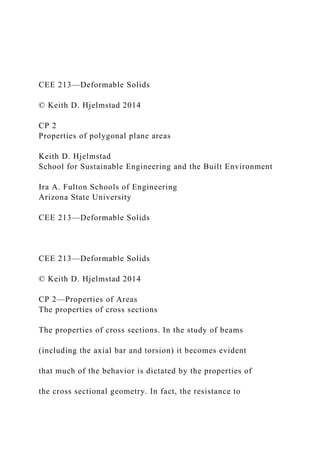
  • 4. For beam theory we need to compute area and moment of inertia (about the centroid). To compute the moment of inertia we need the location of the centroid. The area is simply defined as the sum of the infinitesimal areas that make up the cross section: y z x h c ρ dA 2 e 3 e r O C
  • 5. A The centroid of an area is defined as follows: 1 A dA A In other words, it is the constant vector c that is the average over the area of the position r of the infinitesimal areas. Finally, the moment of inertia (tensor) is defined as Where the vector r is the distance from the centroid C to the infinitesimal area of integration. 2 1 1 1 2 1 2 2 2 1 2 2 T v v v v v v
  • 6. v v v v v v v v The tensor (or outer) product of vectors CEE 213—Deformable Solids © Keith D. Hjelmstad 2014 CP 2—Properties of Areas The moment of inertia tensor The moment of inertia tensor. The problem with computing J is that it is defined in terms of the centroidal coordinate system. We can compute it in the regular coordinates noting that (by vector addition) y z
  • 8. A A A A A A dA dA dA dA dA dA dA dA A A A dA A
  • 9. J ρ ρ r c r c r r c r r c c c r r c r r c c c r r c c c c c c r r c c 2 2 T y y z z y y z y z z
  • 10. r r r r 1 1 2 2 2 1 1 2 2 1 2 2 T c c c c
  • 11. c c c c c c c c c c Thus, we can compute Therefore, we can compute the moment of inertia tensor in the original coordinate system as A We need the centroidal distance c, and we need to figure CEE 213—Deformable Solids
  • 12. © Keith D. Hjelmstad 2014 CP 2—Properties of Areas The general triangular region The general trianglular region. We can specialize the notion of our cross sectional properties to a general triangular region (shown at left). We will need to get specific about how to do the integrals over this region. Once we have found the results, we can use them as a basic building block in an algorithm to compute the three basic properties of any polygonal cross section (and, by taking points close together we can approximate cross sections with curved edges, too). We will construct our concept of the triangle from the position vectors of the two vertices i and j (which will lie on an edge of the polygon later). These vectors are xi and xj. From these vectors we can compute h, b, and the unit vectors n and m (as shown in the box at left). y z
  • 14. i j h b O O The basic triangle i j i h b x n x x m i j i h
  • 15. b x x x All of these key quantities can be computed from the vectors xi and xj CEE 213—Deformable Solids © Keith D. Hjelmstad 2014 1 1 1 2 3 3 2 sin sin
  • 16. dA d d dA d d d d n m n m x h h x x e n m n m e n m e CP 2—Properties of Areas Integration over the triangle Integration over the triangular region. It will be convenient to set up the area integration in the
  • 17. coordinate system n and m (which happens not to be rectangular). dAdxn dhm ( ) 0 0 0 0 ( ) sin ( ) sin ( ) h w A b h h dA d d d d x x
  • 18. dA x n h m ( ) b w h The variables of integration are x (measures distance in n direction) and h (measures distance in m direction), which are in the range Note how the limits of integration are done in the box at right.
  • 19. Thus, the element of integration is And the integration over the area is done as CEE 213—Deformable Solids © Keith D. Hjelmstad 2014 0 0 00 0 21 2 0 1 2 sin sin sin sin sin
  • 21. CP 2—Properties of Areas Area of the general triangle For beam theory we need to compute area, centroidal location, and moment
  • 22. of inertia (about the centroid): 1 2 dA x n h m ( ) b w h Area of the general triangle. We can compute area of the triangle as follows: Note how “one half base times height” still seems to be things: (1) that the triangle is not a right triangle and (2) if it turns out to be negative then the area is “negative.” The area of the general triangle is CEE 213—Deformable Solids
  • 23. © Keith D. Hjelmstad 2014 0 0 21 2 00 2 2 21 2 0 2 3 31 1 3 6 0 2 21 1 3 6 2 1 3 3 sin
  • 25. h h b h b h A h b x x
  • 26. p r n m n m n m n m n m n m A CP 2—Properties of Areas The centroid of the triangle We will sum the contributions for
  • 27. each triangle so we will not compute c (the location of the centroid) for the cross section until we add up all of the p contributions. dA x n h m ( ) b w h The centroid of the triangle. We can compute the integral of r over the triangle as follows: Note that p is one third of the distance from the edges, but adjusted by the general area A and measured in the directions n and m. The location of the centroid of the general triangle is
  • 28. CEE 213—Deformable Solids © Keith D. Hjelmstad 2014 0 0 2 2 0 0 2 2 31 1 2 3 00 2 3 3 3 31 1 2 3 0 2 4 4 41 1 1 4 8 12 sin sin sin sin
  • 29. sin b h h A b h h b h h h dA d d d d d b b b d h h h b b h h
  • 30. x x x
  • 31. r r n m n m A B C A B C A B C A B 3 0 3 2 2 31 1 1 4 8 12 2 21 1 1 2 4 6 sin h b h
  • 32. b h b h b h A h bh b C A B C A B C A n n B n m m n C m m A
  • 33. B C It is convenient to define tensors CP 2—Properties of Areas outer product of r with itself for the triangular region as follows: Hence, we have the following result (which we will eventually use to compute the moment of inertia) These tensors are constant over the triangle and therefore can be pulled out of the integral. Note that we will not compute the actual moment of inertia about the centroid at this point because we plan to add together multiple pieces to construct the moment of inertia for polygonal regions. So we will simply compute (and accumulate) the
  • 34. integrals of the outer product. The vector r to the elemental point of integration is CEE 213—Deformable Solids © Keith D. Hjelmstad 2014 CP 2—Properties of Areas Positive and negative regions We can compute integrals over a cross section by considering positive and negative areas. In regions where there are both, they cancel each other out. The I-beam, for example, can be constructed from the large (positive) rectangle and the two smaller (negative) rectangles. We will use this general idea to accumulate the contributions of the triangles that define the sides of the and if it is less than zero then the area will be negative. For any region that has both a positive and negative contribution the net effect (in all of our integrals) will be zero. Hence, this is a good way to lay out the calculation.
  • 35. A A A A A w dA w dA w dA w dA w dA (-) (0)(+) + = Zero region Actual cross section Positive region
  • 36. Negative region (+) (-) (-) CEE 213—Deformable Solids © Keith D. Hjelmstad 2014 CP 2—Properties of Areas Accumulation of properties Consider the cross section shown at right. Taking the points sequentially we see the contributions of four then the area is negative (red), otherwise it is positive (blue). Notice how the areas outside the cross section get exactly one positive and one negative contribution. In the end, only the blue region remains. 1
  • 37. 2 3 4 n m n m n m n m The Cross Section Triangle 1 (side 1-2) Triangle 2 (side 2-3) Triangle 3 (side 3-4) Triangle 4 (side 4-1) 1 2 2 3 3 4
  • 38. 1 4 O O O O O CEE 213—Deformable Solids © Keith D. Hjelmstad 2014 CP 2—Properties of Areas Positive regions and negative regions Positive regions and negative regions. The power of the approach we are taking is the ability to distinguish between positive regions and negative regions. When we use the general triangle as the building block for computing integrals over a polygonal shape we must be able to assign a positive or negative value to each piece in accord with the need to either add that portion to the of this issue. Recall the definition
  • 39. According to the definition of cross product, the angle is clockwise from the vector n to the vector m. You can see how this plays out in the two examples below (the triangles for sides 1-2 and 2-3 for our example). The sine function is positive in the first and second quadrant and negative in the third and fourth, and this gives the integrals their algebraic sign. Also, as the vectors tend to point along the same line the magnitude gets smaller (to reflect that the region of the triangle gets smaller). n m n m n
  • 40. m 2 e 3 e CEE 213—Deformable Solids © Keith D. Hjelmstad 2014 CP 2—Properties of Areas Algorithm 1 1 2 2 1 1 1. Store coordinates of vertices in array 2. Initialize properties 0, , 3. Loop over the sides, 1: a. Compute the unit vectors and from b. Compute N N
  • 41. i i x y x y x y x y A i N x x p 0 R 0 n m x
  • 42. 1 sin c. Compute the triangle contributions , , and d. Add the contributions to the whole , , 4. Finish the computation of and / , 5. Com i i i i i i i i i A A A i i i A dA dA dA A A A A A
  • 43. n m e p r R r r p p p R R R c J c p J R c c pute principal values of 6. Print and plot results J 1 2 3 4 The Cross SectionO
  • 44. Algorithm. We can organize the computation as follows: The process can be put into a program with the steps outlined at right. In the loop we carry out the computations associated with the triangle whose edge is defined by the current vertices. We then accumulate those into sums for each of the properties (i.e., we are adding up all of the contributions of all triangles). Once the loop is complete we can finish the computations of c and J, find the principal values, and print and/or plot the results. CEE 213—Deformable Solids © Keith D. Hjelmstad 2014 CP 2—Properties of Areas Principal values of J Principal values of J. When the off-diagonal elements of the tensor J are not zero that implies that the Jyy and Jzz values are not the maximum or minimum moments of
  • 45. inertia of the cross section. The way we computed J had the first step of laying down a coordinate system (y, z). We found the location of the centroid C and that allowed us to nail down the coordinate system (x,h), which is simply a translation of the original coordinate system to pass through the centroid. These two coordinate systems were probably chosen because of some other aspect of the problem we are trying to solve (e.g., bending about the y-axis). But, as far as the properties of the cross section are concerned, the choice is arbitrary. An interesting question to ask is this: Could we pick a coordinate system (x',h') in such a way that the values of Jyy and Jzz are the biggest or smallest possible? The answer is “yes” and the coordinate system we need points in the direction of the eigenvectors of J. Similarly, the actual max/min values are the eigenvalues of J. MATLAB gives us a very easy way to compute the eigenvalues of a matrix: 2
  • 46. e 3 e C x h y z Jmax = eig(J) The maximum and minimum values of the inertia tensor J are its eigenvalues. These are the values of J that we would compute in the (x',h') coordinate system (if we knew what it was in advance). For a symmetric cross section J is diagonal and the the max/min values are equal to the diagonal elements of J. Guidelines for Doing Computing Projects
  • 47. The Mechanics Project Keith D. Hjelmstad 08.19.2015 Introduction The Computing Projects are designed to promote a different kind of thinking about me- chanics and to provide a different mechanism for demonstrating understanding of the sub- jects. The each computing project culminates in a written report. The main purpose of the computing projects is to experience an authentic and complete cycle of engineering problem solving. Recitation and exam problems (and virtually all problems that you might find in the back of a textbook) are very limited in scope, very prescriptive in what is given and what is required, and generally more about a snapshot of the state of a system in time rather than the evolution of that system (for dynamics). Com- puting projects usually involve computations that are not practical to do by hand. Once you have a working code, you can execute it for different inputs very easily. That opens up the possibility of examining the effects of the variables and seeing how a system responds over a broad array of input values. That is a prerequisite to any design problem. The way we can get to this view is through numerical computations. That is what the computing projects are all about.
  • 48. This brief guide is meant to give you an outline of what you should do and how you should report on what you have done. You should also, of course, consult the document Evaluation of Computing Projects to see exactly how the reports will be viewed, by your peers during the Peer Review process and by the Instructional Team at final grading. What should be in the reports? The report should have the following sections: 1. Introduction. In this part of the report you present the problem statement. You can summarize from the assignment sheet, but it needs to be your take on the assign- ment. 2. Theory. You need to present the equations that your computer program is based on. If the equations were not given to you then you need to include a derivation of those equations. If you present an equation without derivation give reference to where you got it. Make sure that every symbol you use in your equations is defined somewhere in the text (usually immediately after it is introduced). Make sure that The Mechanics Project Guidelines for Doing Computing Projects
  • 49. 2 your equations meet the standards of report presentation (i.e., they must be typeset using Microsoft Equation 3.0 or equivalent). Do not use MATLAB code notation in the presentation of the theory. It should go without saying that the code has to work—and that does not just mean that MATLAB is no longer bugging you about syntax errors, but that the program is actually computing what you want it to—i.e., it is computing numerically what the theory sets out theoretically. Not only does the code have to work, you have to prove that it works. This process is called verification of the code. Verification means that you can demonstrate that the code generates results that match the solution to the problem done by some independent approach (e.g., using the exact classical solution) or matches the re- sults in some independent source in the reputable literature. Verification is probably the most important and transferrable engineering skill that you will learn through these projects. How do you know when an answer is correct if there is no result in the back of the book to check it with? This is what engineers do. There are many ways to go about verification that span from the qualitative to the quantitative. Pay attention to it; document it.
  • 50. 3. Study and Results. Every report has to be about something. The purpose of these projects is not only to write a program, but also to use that program to explore and discover something about the problem at hand. It is not about “getting an answer” but developing and using an engineering tool. Describe what your study is about (there is a specific section in the grading rubric that asks if you have done that). In this part of the report you will run the program with different inputs and you will need to summarize what you find. Do not simply paste the output of the pro- gram or graphics produced by the program into the report. If you have, for exam- ple, studied how things change when you vary one of the parameters, put your results into a spreadsheet, generate a professional plot, and put that plot into the report. Synthesize information; look for trends. In your report, label every table and figure. Table labels go on top of a table. Label them Table 1, Table 2, etc. Figure labels go below a figure. Label them Fig. 1, Fig. 2, etc. You might want to include text in your table and figure labels to describe what they are about. It is always a joy to read a report that can be largely under- stood by looking at pictures are reading the captions to those pictures. But, even if you do use fairly complete captions, you still need to refer to every table and figure,
  • 51. by number, in the text of your report. If you use references then provide a reference list in an accepted bibliographic format. Your study needs to meet standards of scientific and engineering competence. Don’t just make stuff up. Use good scientific and engineering judgment and use the process to develop your scientific and engineering judgment. The Mechanics Project Guidelines for Doing Computing Projects 3 4. Conclusions. The study must have conclusions and they must relate to the study (there is a specific section in the grading rubric that asks if your conclusions con- nect to information provided in the report). The conclusions do not have to be lengthy, but they should say something coherent about the problem at hand. This is not a place to speculate, it is not that useful to invent future applications. In general, it is not a good idea to talk about how valuable the learning experience was—let’s just take that as a given. The conclusions should emanate from the study. 5. Appendix A—MATLAB code. Always include your complete
  • 52. MATLAB code in an appendix to the report. This will allow the reader to easily look over your code. The code should be nicely presented, with comments, indentation, and other fea- tures that help to make it readable. It is very easy to select your entire .m file and paste it into Word keeping the source format. You probably will need to change the font size to 8 point to get the code to fit. It is also a good idea to never go beyond the vertical line on the right side of the MATLAB editor. If you stay on the left of that line then when you paste your code you will not have word wrap on a line of code. You should think about your program as something someone else will read, not just something that you understand because you suffered through every line. Even you will forget what you were thinking a few weeks later if the code is not well documented. And remember, plagiarism applies to computer code just like it does to writing. Do your own work. 6. Appendix B—Derivations. Include any detailed derivations in an appendix, not in the body of the report. For many computing projects, the derivation of the theory is part of a recitation problem. In such a case you can simply put the derivation from the homework in the appendix. If the derivations are complete in the Course Notes then it is sufficient to refer to those results in the text. No
  • 53. need to include the derivations, even as an appendix, if the results are available in a reference docu- ment. If you have these six sections in your report then you are off to a good start. You can have more sections, but you should not have fewer. Write the report so that someone who was not a part of the process can make sense of it. Is there a difference between complete and good? The report has to be both complete and good and there are a few things that will make it good. “Complete” means you get everything done. It means the theory is there, the code works, you proved that the code works (the report should deal specifically with verification of the code—this is very, very important), you did at least the computations called out in the assignment document, and you wrote a report to document what you did. The Mechanics Project Guidelines for Doing Computing Projects 4 “Good” is not the same as complete. Good means that your derivations are very well done. It means that your code is not a big mess. It means that you don’t say nonsensical things
  • 54. about how the world works (there is a specific part of the grading rubric that concerns scientific competence—that is what it means: you say things that any self-respecting tech- nical person can interpret correctly and those things are not at odds with what is known about the universe at this time). The quality of the report is about how well you write, your attention to important details, and how good the report looks. The report needs to look like it was done by a professional. If you put a plot in your report make sure it meets professional standards. If you include a sketch, make sure it is neat, correct, and easily interpreted. The purpose of graphics is to communicate ideas that are more difficult to convey in words. If the reader cannot make heads or tails of your graphics then you have not communicated. If there is missing infor- mation then you have not communicated. If the information is ambiguous then you have not communicated. Most of these things are common sense and the best rule is the “golden rule”: do unto others as you would have them do unto you. Would you want to read your report? If you had to reproduce the results in your report from the information in the report, could you? One of the main reasons for including peer review is to give the opportunity to take on the role of reader of reports. What you learn from reading the work of others should help you to avoid things that make it hard to read.
  • 55. You can always seek feedback from the Instructional Team about how to do the projects and how to write the reports. In-class Code Checks As with any larger task, the computing projects will take time and may require a bit more management of your time than ordinary homework does. Because computer programming is involved you really have nothing until your program works (and then you have pretty much everything). In order to write a report that will get you the credit you want and need, you will have to get the programs working with enough time left to do the exploration and report writing required. So plan accordingly! To encourage good time management, we will execute in-class code checks in accord with the dates listed in the syllabus and course schedule. The code checks are scheduled during recitation time. Each student will be asked to run their code for someone on the instruc- tional team. You will be granted a significant amount of credit towards the overall grade for the CP based upon this code check. To get full credit come to that recitation with a working code! The code check is generally scheduled one week prior to the due date for the report, fos- tering an appropriate amount of time for exploration and discovery.
  • 56. The Mechanics Project Guidelines for Doing Computing Projects 5 Peer Review in Critviz Written reports as learning vehicles are substantially better if the student has an opportunity to get feedback and to improve the report based on that feedback. Furthermore, students can gain valuable perspective on the overall task of inquiry and communication through reviewing the work of others. You can see examples from others of good things to do and you can provide suggestions to others on how to improve the product. It creates a more democratic answer to the question “what is the instructor looking for?”1 In this case you can learn a great deal from each other. We will use the mechanism of peer review as part of the Computing Project process. Critviz is a program for managing the peer review process. It allows the submission of work, it randomly distributes the work for peer review, and it displays the outcome of the process. The peer review process is anonymous (i.e., you should not know who’s report you are reviewing). To maintain anonymity you are responsible for eliminating identifying infor- mation on your report. Use your ASU posting ID as the
  • 57. identifier on your work. Each project gets five reviews. Having five reviews provides redundancy in the process and enhances the likelihood of generating valuable comments. As a peer reviewer, you are responsible for writing comments in response to the submitted projects of your five as- signed peers. You will also rank your five projects (1 is the best, …, 5 is the “least best”). Rank each project uniquely with no ties. An average ranking is computed by Critviz and the top few projects are selected on this basis to be highlighted in by Critviz. The remaining projects are also displayed, but in al- phabetical order. It is important to note that after the review process is complete the projects and reviews of all students are visible to all students in the class on the Critviz website (but not to anyone outside of our class). This public forum gives you the opportunity to show your work and it gives you the opportunity to see how others have interpreted the assignment and the requirements. This knowledge should help you to improve future reports. Submission and Peer Review Process Here is how the submission and peer review process will work: 1. Each student completes a project report by the due date and submits that report to the Critviz website (www.critviz.com). Your report should be
  • 58. anonymous for the peer review process so use your ASU posting ID rather than your name on your documents and in your code. All projects are due in accord with the course sched- ule. 1 While an expert opinion might be more fully developed, your opinions are also valuable. Further, taking on the responsibility of providing a critique of the work of others is a fantastic way to advance your own per- spective of your own work and to develop expertise. The Mechanics Project Guidelines for Doing Computing Projects 6 Reports must be submitted in .pdf format! It is a good idea to upload a version early so that you are guaranteed to have some- thing. You can always upload again. When you do that, Critviz replaces the file submitted earlier. Click on the file you have just uploaded to make sure it is there and to make sure it is the one you intended to submit. 2. Critviz automatically (and randomly) assigns the peer reviews at a specific time. Only students who submit projects by the deadline are included in the peer review
  • 59. process for that project. If you miss the submission deadline then you missed the boat for peer review. Don’t risk being late. Critviz has a countdown clock to help you out with that. 3. Each project report is distributed to five other students for their review and com- ment. The reviews are due by the date established in the course schedule. Note: Critviz closes the review phase at a specific, preset time. So late reviews cannot be accepted. Note that if peer review is not part of the submission (it is not done for every course in The Mechanics Project), then it is not necessary to maintain anonymity. In such a case, make sure your name and posting ID are on your work. What makes a good peer review? The reviews should be informed by the rubric outlined in the document Evaluation of Com- puting Projects. That is the guide that the instructional team will use. However, your task as a peer reviewer is not to “grade” the project (i.e., there is no need to provide a numerical score for each rubric area). The task of the peer reviewer is to write comments for each of the three main areas. Your main role as reviewer is to provide feedback on the report. The best feedback will promote actions on the part of the author to improve the report. As such,
  • 60. subjective comments on quality (like “this is great” or “this is not great”) are not that helpful. Comments that give specific suggestions or specific direction are better. As you write your comments put your- self in the author’s position of needing to read those comments and actually do something about it. Are you making implementable suggestions or are you asking the impossible? Do unto others as you would have them do unto you! This peer review process is exactly the process used for articles submitted to research jour- nals. In the real world, this is how the community helps to decide what is worthy of publi- cation and what is not. Generally, the reviewer is an “expert” in the field and is asked to provide an “expert” opinion. In practice, every article you review in that arena is a new contribution to the state of the art, so no person is really expert enough to have already solved that problem. So if you think of yourself as somehow not capable of providing peer review of work because you are still learning, think again. We are all learning, but we all The Mechanics Project Guidelines for Doing Computing Projects 7 know something. And through the process of providing your best review you improve your
  • 61. ability to review. Peer review is valuable only if the quality of the reviews is high. Therefore, we will gen- erally associate a portion of the project grade with the quality of your peer reviews (i.e., how you review others counts in your project grade). Quality will generally be associated with insightful and helpful comments. Assigning rubric points is not quality. Cheerleading is not quality. Implementable guidance is quality. The peer reviews do not have to be long to get full marks for peer review (but a few sentences is probably not enough). CEE 213—Deformable Solids The Mechanics Project Arizona State University CP 2—Properties of Areas 1 Computing Project 2 Properties of Areas The computing project Properties of Areas concerns the computation of various properties of cross sectional areas. In each of our theories (i.e., axial bar, torsion, and beams) we arrive
  • 62. at a point where we need certain properties of the cross section to advance the analysis. For the axial bar we needed only the area; for torsion we needed the polar moment of inertia; for the beam we will need moment of inertia of the cross section about the centroid of the cross section. We can develop an algorithm that allows the computation of all of the properties of a cross section if the cross section can be described as a polygon. The algorithm is built on formu- las for the properties of a triangle. What that program will do is create a triangle from the origin and the two vertex nodes associated with a side of the polygon. Whether this polygon adds or subtracts from the accumulating properties will be determined from the vectors defining the sides of the polygon (see the CP Notes for further clarification). If you loop over all of the sides, the end result will be the properties of the entire cross section. The general steps are as follows: 1. Develop a routine that allows you to describe the cross
  • 63. section with a sequence of points numbered in a clockwise fashion starting with 1. The last point should be a repeat of the first one in order to close the polygon. Some suggestions: a. Store the (x,y) coordinates of each point in a single array x(N,2), where N is the number of points required to describe the cross section (including the repeat of the first point as the last point) and the first column contains the x values of the coordinate and the second column contains the values of the coordinate and the second column contains the y value. b. It will eventually be a good idea to put the input into a MATLAB function and call the function from your main program. That way you can build up a library of cross sectional shapes without changing your main program. c. If you need a negative area region (for a cutout section like in an open tube) then number the points in that region in a counter- clockwise fashion.
  • 64. Just keep numbering the vertices in order (no need to start over for the negative areas). 2. Develop a routine to loop over all of the edges of the polygon and compute (and accumulate) the contributions of the triangle defined by the vectors from the origin to the two vertices of the current side of the triangle (that gives two sides) and the CEE 213—Deformable Solids The Mechanics Project Arizona State University CP 2—Properties of Areas 2 vector that points from the first to the second vertex (in numerical order). Calculate the area, centroid, and outer-product contributions to the properties (see the CP Notes for clarification of this issue). 3. Compute the orientation of the principal axes of the cross section using the eigen- value solver in MATLAB (eig) on the moment of inertia matrix
  • 65. J. See the CP Notes for more information on this task. 4. Create an output table (print into the Command Window) giving the relevant cross sectional properties. Develop a routine to plot the cross section. Include the loca- tion of the centroid of the cross section in the graphic along with lines defining the principal axes. 5. Generate a library of cross sections, including some simple ones (e.g., a rectangular cross sections) to verify the code. Include in your library as many of the following cross sections as you can get done: a. Solid rectangle with width b and height h. b. Solid circle of radius R. c. Rectangular tube with different wall thickness on top and bottom. d. I-beam with flange width b, web depth d, flange thickness tf, and web thickness tw. e. Angle section with different leg lengths and leg thicknesses.
  • 66. f. Circular tube with outside radius R and wall thickness t. g. T-beam. 6. Use the program to explore aspects of the problem. For example, a. Why is it more efficient to use an open circular tube for torsion rather than a solid cylinder? b. For beam bending we can control deflections and reduce stresses with a large moment of inertia about the axis of bending. Show the trade-offs available in an I-beam when you can select different web and flange depths and thicknesses. c. Explore any other feature of the problem that you find interesting. Write a report documenting your work and the results (in accord with the specification given in the document Guidelines for Doing Computing Projects). Post it to the Critviz website prior to the deadline. Note that there is only one submission for this problem (the
  • 67. final submission). CEE 213—Deformable Solids The Mechanics Project Arizona State University CP 2—Properties of Areas 3 Please consult the document Evaluation of Computing Projects to see how your project will be evaluated to make sure that you can get full marks. Note that there is no peer review process for reports in this course.