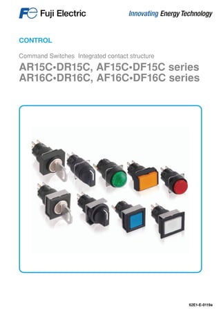
Command Switches Integrated contact structure
•
0 likes•1,512 views

This document provides contact and address information for the head office and branch offices of a company that distributes industrial electrical equipment in Vietnam. It lists the addresses, phone numbers, and fax numbers for the company's offices in Hanoi, Cambodia, and Binh Duong. It also includes the company's slogan "Think Together" in Vietnamese.

Recommended
Recommended
More Related Content
What's hot
What's hot (10)
Viewers also liked
Viewers also liked (17)
Similar to Command Switches Integrated contact structure
Similar to Command Switches Integrated contact structure (20)
More from CTY TNHH HẠO PHƯƠNG
More from CTY TNHH HẠO PHƯƠNG (20)
Recently uploaded
Recently uploaded (20)
Command Switches Integrated contact structure
- 1. CONTROL Command Switches Integrated contact structure 62E1-E-0119a
- 2. Ha Noi Office: No. 95 - TT4, My Dinh Urban Area, My Dinh, Nam Tu Liem, Hanoi. Tel: (84 4) 3568 3740 Fax: (84 4) 3568 3741 Cambodia Office: #140, Room 1-B, St430, Sangkat Toul Tompuong II, Khan Chamkamon, PP. Tel: 855 2322 3635 Fax: 855 2322 3645 Head Office: No 88, Vinh Phu 40, Hoa Long, Vinh Phu, Thuan An, Binh Duong. Tel: (84 650) 37 37 619 Fax: (84 650) 37 37 620 1800 6547 THINK TOGETHER Nhà phân phối thiết bị điện công nghiệp hàng đầu Việt Nam T
- 3. 2 42.5mm 35.9mm 28.4mm 28mm 2mm Ø16 Command Switches An integrated structure with built-in contacts that can reduce control panel depth. A wide variety of sockets are available to simplify wiring. A structure that integrates operator and contacts to reduce panel-mounting depth. Terminals extending to the rear of the switch ensure easy wiring work. Switches combine with a variety of sockets to simplify wiring. Applicable as a fast-connection terminal switch by combining the socket with a switch. Easily wired by simply removing the wire sheath and inserting the wires while pressing the insertion slot button (no soldering required). Incorporates a branch terminal for easy branching. Applicable as a connector by combining the socket with receptacles. The socket holds the receptacles, making it easy to connect the receptacle to the switch with a single operation. Applicable as a switch for PC board by combining the socket with a switch. Pattern wiring reduces the number of wiring man-hour and helps prevent faulty wiring. Mounting panel AR15C・ AR16C・ ・ ・ AH164, 5 series (Contact separated type) Lock lever Insertion slot button Receptacle Lock lever
- 4. contact mechanism Gold-plated contacts and a snap- action mechanism enables IC-level applications (with a switching current of 1 mA at 5 V). 3 Bezel (Standard) Keep in mind that the panel cutout size for the thin type depends on the operator shape. The key selector switch incorporates a pin tumbler type key (reversible type) to improve the insertion/ extraction performance of the key. Washer Tightening nut Six key types are available. The pin tumbler construction improves security. In addition to the standard type, a thin type with a panel protrusion of only 2 mm is available, allowing high-density mounting for attractive panel designs. ・ ・ The AR16V types feature a panel depth dimension of 28 mm for non-illuminated models and can have up to four sets of contacts. With regard to the degree of protection, AR15C・AF15C series which met the requirements of IP40 of IEC 60529, and AR16C・AF16C series which meet the requirements of IP65 of the said, are available. This permits the application to various fields, from machine tools to OA(Office Automation) facilities. IP40 : AR15C・DR15C, AF15C・DF15C IP65 : AR16C・DR16C, AF16C・DF16C Standard models meet UL/CSA requirements, China Compulsory Certification (CCC) standards, and TÜV EN standards, making them ideal for equipment for export. Meets EU RoHS Standard models meet RoHS requirements (EU Directive 2002/95/C). Fast-Connection socket Connector socket Socket for PC board AR15C・ ・ AR16C・ ・ AR16V0R AR16V0L Non-illuminated Illuminated 28mm 31.5mm
- 5. 4 Overview .................................................................................................... 2 Safety precautions ..................................................................................... 7 Glossary .................................................................................................... 8 Selection guide........................................................................................... 9 Featurers, specifications .......................................................................... 13 Type number nomenclature...................................................................... 16 Type numbers and dimemsions ................... 20 Pushbutton switches ................................................................. 22 ..................................................... 24 ................................................... 26 ..................................................... 29 ................... 32 Pushbutton switches ................................................................. 34 ..................................................... 36 ................................................... 38 ..................................................... 41 Panel cutting and mounting...................................................................... 44 Notes on use............................................................................................ 46 Accessories.............................................................................................. 52 Mass .................................................................................................. 56 AR16V Rating and specifications ......................................................................... 57 Type numbers........................................................................................... 59 ................................................................... 60 Notes on use............................................................................................ 61
- 6. 5 Product Index ............................. 32 ............................ 32 ............................. 32 ............................. 34 ............................. 34 ............................. 34 ............................. 32 ............................ 32 ............................. 32 ............................. 34 ............................. 34 ............................. 34 ......................... ......................... ......................... ......................... ......................... ......................... ............................. 32 ............................ 32 ............................. 32 ............................. 34 ............................. 34 ............................. 34 ............................. 32 ............................ 32 ............................. 32 ............................. 34 ............................ 34 ............................. 34 ......................... ......................... ......................... ......................... ......................... ......................... ............................... 52 ................................ 52 ................................ 54 ................................ 54 ................................ 54 ................................ 54 ................................ 54 ................................ 54 ................................. 54 AHX618 ................................ 54 AHX622 ................................. 54 AHX644 ................................. 54 AHX645 ................................. 54 AHX668 ................................. 52 ................................. 52 ................................. 52 ................................. 54 AHX822 ................................. 52 AHX826 ................................ 52 ................................. 54 ............................. ............................ 22 ............................. AR15E5RC ............................ 22 ............................ ............................ ............................. 22 ............................. 22 ............................ ............................ ............................. 22 ............................. 22 ............................ ............................ 22 ............................ ............................ 22 ......................... ......................... ......................... AR15PRC ........................ ........................ ......................... ............................. ............................ 22 ............................. AR16E5RC ............................ 22 ............................ ............................ ............................. 22 ............................. 22 ............................ ............................ ............................. 22 ............................. 22 ............................ ............................ 22 ............................ ............................ 22 ......................... ......................... ......................... AR16PRC ........................ ........................ ......................... ............................... ............................... ............................... AR16V1R............................... AR6C631 ............................... 55 AR6C632 ............................... 55 AR6C633 ............................... 55 AR6C662 ............................... 55 AR6P665 ............................... 55 AR6P666 ............................... 55 ............................... 55 ............................... 53 ............................... 53 ............................... 52 ............................. 24 ............................. 36 ............................ 36 ............................. 36 ............................. 36 ............................ 36 ............................. 36 ............................. 24 ............................ 24 ............................ 24 ............................ 24 ............................. 24 ............................ 24 ............................ 24 ............................... 55 ............................ 55
- 7. 6 The information contained in this catalog does not constitute an express or implied warranty of quality, any warranty of merchantability of fitness for a particular purpose is hereby disclaimed. Since the user's product information, specific use application, and conditions of use are all outside of Fuji Electric FA Components & Systems'control, The products identified in this catalog shall be sold pursuant to the terms and conditions identified in the "Conditions of Sale" issued by Fuji Electric FA with each order confirmation. Except to the extent otherwise provided for in the Conditions of Sale issued by Fuji Electric FA, Fuji Electric FA warrants that the Fuji Electric FA products identified in this catalog shall be free from significant defects in materials and Electric FA at 5-7, Nihonbashi Odemma-cho, Chuo-ku, Tokyo, Japan. The sole and exclusive remedy with respected to the above warranty whether such claim is based on warranty, contract, negligence, strict liability or any other theory, is limited to the repair or replacement of such product or, at Fuji Electric FA's option reimbursement by Fuji Electric FA of the purchase price paid to Fuji Electric FA for the particular product. Except as provided in the Conditions of Sale, no agent or representative of Fuji Electric FA is authorized to modify the terms of this warranty in writing or orally. In no event shall Fuji Electric FA be liable for special, indirect or consequential damages, including but not limited to, loss of use of the product, other equipment, plant and power system which is installed with the product, loss of profits or revenues, cost of capital, or claims against the purchaser or user of the product by its customers resulting from the use of information, recommendations and descriptions contained herein. The purchaser agrees to pass on to its customers and users, in writing at the time inquiries and orders are received by buyer, Fuji Electric FA's warranty as set forth above.
- 9. 8 Classification Rating Operating environment Degree of protection Types of pilot lights and illuminated switches Operational functions Term Rated insulation voltage (Ui) Rated operational voltage (Ue) Rated impulse withstand voltage (Uimp) Conventional free air thermal current (Ith) Rated operational current (Ie) Pollution degree IP code Pilot lights without transformer Illuminated switch without transformer Momentary Alternate Maintained Spring return Spring/manual return Explanation A voltage value that serves as a reference when designing a device and satisfies the clearance and creepage distance and the withstand voltage (dielectric strength) of the device. A voltage value applied to a device under specified conditions.If the device is a control switch, the rated operational voltage (Ue) in combination with the rated operational current determines the equipment that it is to be applied to. Furthermore, the rated operational voltage (Ue) determines the relevant tests and operating load type of the control switch.If the control switch is an illuminated type, the term "lamp operational voltage" is applied in this catalog in order to distinguish it from the rated operational voltage of the switch. This is the peak value of an impulse voltage that has a specified waveform and polarity and that is capable of being withstood by a device under specified test conditions, and serves as a reference for clearance. The maximum value for an electric current used to test the temperature rise of a control switch. An electric current applied under specified conditions. A factor used for determining the clearance and creepage distance of a device. There are four pollution degrees according to the pollutants in the operating environment, such as the dust in the air. Fuji’s Command Switches are applicable to pollution degree 3. Pollution degree 3 refers to the occurrence of conductive pollution or the occurrence of conductivity as a result of condensation, but the occurrence of dry, nonconductive pollution in normal, dry conditions. It applies to environments typical of manufacturing plants. The IP code stipulates the degree of protection of a device provided by its enclosure against the ingress of solid matter and water according to IEC 60529. The IP code is expressed with the code letters IP (Ingress Protection) followed by two digits. The first characteristic digit indicates the degree of protection against the ingress of solid foreign objects. The second characteristic digit indicates the degree of protection against the ingress of water. A pilot light or illuminated switch designed so that the voltage of the electric circuit can be applied directly to the light source. The contacts operate when the pushbutton is pressed and automatically reset when the pushbutton is released. The contacts operate when the pushbutton is pressed and the actuated state is held (locked) when the pushbutton is released. The contacts are reset when the pushbutton is pressed again. The knob (key) of selector switch is operated and reset by hand. The contacts are interlocked according to each knob (key) operation. The knob (key) of the selector switch and the contacts are automatically reset to the normal position if the knob (key) is released while the knob (key) is being actuated. Manual and automatic knob (key) resetting methods combined and applied to three-notch selector switches. Pilot light Illuminated switch Ex. ba b NC NOCOM a Note: The terms of a, b, COM, NC and NO indicate the terminal numbers Command Switches
- 10. Command Switches Illuminated pushbutton switches Operator Flush rectangular Flush rectangular with guard IP40 IP65 IP40 IP65 Operator action Momentary Alternate Momentary Alternate Momentary Alternate Momentary Alternate Type Appearance S S Operator Flush square Extended round IP40 IP65 IP40 IP65 Operator action Momentary Alternate Momentary Alternate Momentary Alternate Momentary Alternate Type Appearance S S Pushbutton switches Operator Flush rectangular Flush rectangular with guard IP40 IP65 IP40 IP65 Operator action Momentary Alternate Momentary Alternate Momentary Alternate Momentary Alternate Type Appearance S S Operator Flush square Extended round IP40 IP65 IP40 IP65 Operator action Momentary Alternate Momentary Alternate Momentary Alternate Momentary Alternate Type AR15E5RC AR16E5RC Appearance S S Pilot lights Operator Flush rectangular Flush square IP40 IP65 IP40 IP65 Type Appearance S S Operator Extended round IP40 IP65 IP40 IP65 Type Appearance S S
- 11. Command Switches Operator Knob with rectangular bezel Knob with square bezel Knob with round bezel No. of position 2-position, 3-position 2-position, 3-position 2-position, 3-position Operator action Maintained, Spring/manual return, Spring return Maintained, Spring/manual return, Spring return Maintained, Spring/manual return, Spring return IP40 IP65 IP40 IP65 IP40 IP65 Type AR15PRC AR16PRC Appearance S S S Operator Key with rectangular bezel Key with square bezel Key with round bezel No. of position 2-position, 3-position 2-position, 3-position 2-position, 3-position Operator action Maintained, Spring/manual return, Spring return Maintained, Spring/manual return, Spring return Maintained, Spring/manual return, Spring return IP40 IP65 IP40 IP65 IP40 IP65 Type Appearance S S S Emergency stop illuminated pushbutton switches Operator Illuminated push-lock Illuminated push-lock Operator action Turn reset or pull reset Turn reset or pull reset IP65 IP65 Type Appearance S S Emergency stop pushbutton switches Operator Push-lock Push-lock Operator action Turn reset or pull reset Turn reset or pull reset IP65 IP65 Type AR16V1R Appearance S S
- 12. 11 Illuminated pushbutton switches Operator Flush rectangular Flush square IP40 IP65 IP40 IP65 Operator action Momentary Alternate Momentary Alternate Momentary Alternate Momentary Alternate Type Appearance S S Operator Flush round IP40 IP65 Operator action Momentary Alternate Momentary Alternate Type Appearance S Pushbutton switches Operator Flush rectangular Flush square IP40 IP65 IP40 IP65 Operator action Momentary Alternate Momentary Alternate Momentary Alternate Momentary Alternate Type Appearance S S Operator Flush round IP40 IP65 Operator action Momentary Alternate Momentary Alternate Type Appearance S Pilot lights Operator Flush rectangular Flush square IP40 IP65 IP40 IP65 Type Appearance S S Operator Flush round IP40 IP65 Type Appearance S Command Switches
- 13. 12 Operator Knob with rectangular bezel Knob with square bezel Knob with round bezel No. of position 2-position, 3-position 2-position, 3-position 2-position, 3-position Operator action Maintained, Spring/manual return, Spring return Maintained, Spring/manual return, Spring return Maintained, Spring/manual return, Spring return IP40 IP65 IP40 IP65 IP40 IP65 Type Appearance S S S Operator Key with rectangular bezel Key with square bezel Key with round bezel No. of position 2-position, 3-position 2-position, 3-position 2-position, 3-position Operator action Maintained, Spring/manual return, Spring return Maintained, Spring/manual return, Spring return Maintained, Spring/manual return, Spring return IP40 IP65 IP40 IP65 IP40 IP65 Type Appearance S S S Command Switches
- 14. 13 Command Switches that reduces control panels’ depth. A unified depth of 28.4mm for the Standard type and 35.9mm for the Thin type. design. Select an optimum one to match your control panel design. mechanism with a snap-action structure that makes and breaks 1mA at 5V. type mechanism provides improved key insertion and Contact rating code 120V 240V Making current Making current 3.6A 0.6A 1.8A 0.3A Type of switches Conventional free air thermal current Ith Rated operational current Ie Rated operational AC AC-13 AC-12 Illuminated pushbutton switch Pushbutton switch Selector switch 5A 24V – – 0.7A *1 1A 120V 1A 1.5A – – 125V – – 0.15A *1 0.2A 240V 0.7A 1A – – Note: *1 T0.95
- 15. 14 Command Switches Item Illuminated pushbutton switch, pushbutton switch Selector switch Pilot lights Mechanical Momentary action: 1 million operations Alternate action: 250,000 operations Maintained: 250,000 operations Spring/manual return: 250,000 operations Spring return: 250,000 operations – Electrical – Operating frequency – Withstand voltage 2000V AC, 1 minute 2000V AC, 1 minute – Insulation resistance 100Mȍ 2.5kV Conditional short-circuit current 1000A Short-circuit protective device Pollution degree 3 Vibration Shock 2 2 Operational ambient temperature Storage temperature –40 to +70°C IP2X (Fast-connection socket: AR6S690, Connector socket: AR6S691-C or Ietm Fast-connection socket Connector socket Socket for PC board Conventional free air thermal current Ith 3A 5A 3A 2.5kV 0.5kV 2000V AC, 1minute 1000V AC, 1minute Insulation resistance 100Mȍ Operational ambient temperature Storage temperature –40 to +70°C Relative humidity Pollution degree 3 depending on the operational ambient conditions and type of load.
- 16. 15 Command Switches Applied method Lamp operational voltage Type Lamp rated voltage Current consumption without transformer Note: A box Illuminated pushbutton / pilot light color Luminous color of high-brightness Type Type Green G Green G Red R Red R White W White P Yellow Y White P Orange A Amber A S Note: *1 A box Type of lamp Judgment criterion Approx. 30000h When the brightness is less than 50% of initial value. CSA C22.2 No.14 TÜV: EN60947-5-1 Pushbutton, Illuminated pushbutton: R50116757 Selector: R50116759 Pilot lights: R50116762 Pilot lights: 2013010305590652 ensuring easier direct or indirect export to North America and European countries with no safety standard concerns.
- 17. 16 Command Switches C2 E3 GAR16 F0NC Product category Operator shape and action Contact arrangement and terminal Category Standard type Thin type Color of button Color Green Red White *1 Yellow Orange Blue LED color Green Red White White Amber Blue Code G R W Y A S Operator shape Flush rectangular Flush rectangular with guard Flush square Extended round Flush round Contact arrangement SPDT 2PDT Code C1 C2 Type of terminal Tab (#110) and solder dual-use terminal Code Standard type Momentary F0NC G0NC F0MC E0LC – Alternate F5NC G5NC F5MC E5LC – Alternate F5NC – F5MC – F5LC Thin type Momentary F0NC – F0MC – F0LC Degree of protection IP40 IP65 IP40 IP65 Code AR15 AR16 AF15 AF16 Note: The button is transparent in color. *1: A combination of the transparent lens and the white legend plate comes to white. Lamp operational voltage and light source Applied method Without transformer Voltage 12V DC 24V DC Code LED B3 E3 AR16 F0TC C2 R Product category Operator shape and action Contact arrangement and terminal Color of button Color Green Red Black *1 White *2 Yellow Orange Blue Code G R B W Y A SOperator shape Flush rectangular Flush rectangular with guard Flush square Extended round Flush round Contact arrangement SPDT 2PDT Code C1 C2 Type of terminal Tab (#110) and solder dual-use terminal Code Standard type Momentary F0TC G0TC F0SC E0RC – Alternate F5TC G5TC F5SC E5RC – Alternate F5TC – F5SC – F5RC Thin type Momentary F0TC – F0SC – F0RC Notes: The button is transparent in color. *1: A combination of the transparent button and the black legend plate comes to black. *2: A combination of the transparent button and the white legend plate comes to white. Category Standard type Thin type Degree of protection IP40 IP65 IP40 IP65 Code AR15 AR16 AF15 AF16 Note: The manufacturing range varies depending on the this catalog.
- 18. Command Switches E3 WDR16 D0LC Product category Lens shape Color of lens Color Green Red White *1 Yellow Orange Blue LED color Green Red White White Amber Blue Code G R W Y A S Lens shape Flush rectangular Flush square Extended round Flush round Dome Code Standard type F0NC F0MC E0LC – D0LC Thin type F0NC F0MC – F0LC – Note: The lens is transparent in color. *1 : A combination of the transparent lens and the white legend plate comes to white (except for dome type). Note: The terminal used is a tab (#110) and solder dual-use terminal. Lamp operational voltage and light source Applied method Without transformer Voltage 12V DC 24V DC Code LED B3 E3 Category Standard type Thin type Degree of protection IP40 IP65 IP40 IP65 Code DR15 DR16 DF15 DF16 Note: The manufacturing range varies depending on the this catalog.
- 19. 18 Command Switches 2 C1 BAR16 PTC Product category Contact arrangement and terminal Contact arrangement SPDT *1 2PDT Code C1 C2 Type of terminal Tab (#110) and solder dual-use terminal Operator shape Operator shape Knob with rectangular bezel Knob with square bezel Knob with round bezel Code PTC PSC PRC Color of knob Color Black Code B Note: *1 2-position model only available No. of positions and operator action No. of positions 2-position (90°) 3-position (45°) Operator action Maintained Spring return (Right to left) Maintained Spring/manual return (Left to center) Spring/manual return (Right to center) Spring return (Left or right to center) Code 2 0 3 6 7 1 Category Standard type Thin type Degree of protection IP40 IP65 IP40 IP65 Code AR15 AR16 AF15 AF16
- 20. Command Switches AR16 JTC 3 E C2 A Product category Contact arrangement and terminal Contact arrangement SPDT *2 2PDT Code C1 C2 Type of terminal Tab (#110) and solder dual-use terminal Operator shape Operator shape Key with rectangular bezel Key with square bezel Key with round bezel Code JTC JSC JRC Types of key Type *1 Code A A B B C C D D E E F F Note: *2 2-position model only Key removable position Key removable position Left Left and right Left, center and right Right Center Center and right Left and center Applicable operator action 2 – – – – 0 – – – – – – 3 6 – – – – 7 – – – – 1 – – – – – – Code A B C D E F G Note: *1 “A” is standard. No. of positions and operator action No. of positions 2-position (90°) 3-position (45°) Operator action Maintained Spring return (Right to left) Maintained Spring/manual return (Left to center) Spring/manual return (Right to center) Spring return (Left or right to center) Code 2 0 3 6 7 1 Category Standard type Thin type Degree of protection IP40 IP65 IP40 IP65 Code AR15 AR16 AF15 AF16
- 21. Command Switches AR16 F0NC – C2 E3 G Product category: Standard type Operator shape and action Color of button Lamp operational voltage and light source Contact arrangement and terminal Operator and Appearance Lamp operational voltage Conntact arrangement Momentary action Type Alternate action Type IP40 IP65 IP40 IP65 Flush rectangular Flush rectangular with guard Flush square Extended round Note:See page 21 for the outline dimensions. Replace the mark by the color code Color Green Red White Yellow Orange Code G R W *1 Y A S Note: *1 A combination of the transparent button and the white legend plate comes to white.
- 22. 21 Command Switches 24 21 18 15 18sq. 15sq. 18sq. 24 21 18 15 6.57 9.5 Panel thickness 1 to 6 28.4 7 28.4 7 28.4 7 28.4 1515 9.5 6.5 6.5 9.5 159.5 6.5 2.8 10 2.8 10 2.8 10 2.8 10 5.8 0.5 13.6 0.5 5.8 0.5 13.6 0.5 5.8 0.5 13.6 0.5 5.8 0.5 13.6 0.5 Flush rectangular AR15F0NC, F5NC and AR16F0NC, F5NC Flush square AR15F0MC, F5MC and AR16F0MC, F5MC Extended round AR15E0LC, E5LC and AR16E0LC, E5LC Flush rectangular with guard AR15G0NC, G5NC and AR16G0NC, G5NC Nut Washer Nut Washer Nut Washer Nut Washer Packing (AR16 only) Packing (AR16 only) Packing (AR16 only) Packing (AR16 only) Panel thickness 1 to 6 Panel thickness 1 to 6 Panel thickness 1 to 6 18
- 23. 22 Command Switches AR16 F0TC – C2 G Product category: Standard type Operator shape and action Color of button Contact arrangement and terminal Replace the mark by the color code Color Green Red White Yellow Orange Code G R 1 W *2 Y A S Notes: *1 A combination of the transparent button and the black legend plate comes to black. *2 A combination of the transparent button and the white legend plate comes to white. Operator and Appearance Conntact arrangement Momentary action Type Alternate action Type IP40 IP65 IP40 IP65 Flush rectangular Flush rectangular with guard Flush square Extended round Note: See page 23 for the outline dimensions.
- 24. 23 Command Switches 24 18 15 21 18sq. 15sq. 18sq. 24 21 18 15 9.5 6.57 15 2.8 10 2.8 10 2.8 10 2.8 10 28.4 7 28.4 7 28.4 7 28.4 5.8 0.5 5.8 0.5 5.8 0.5 5.8 0.5 6.5 6.5 9.5 9.5 6.5 9.5 15 Flush rectangular AR15F0TC, F5TC and AR16F0TC, F5TC Flush square AR15F0SC, F5SC and AR16F0SC, F5SC Extended round AR15E0RC, E5RC and AR16E0RC, E5RC Flush rectangular with guard AR15G0TC, G5TC and AR16G0TC, G5TC Panel thickness 1 to 6 Nut Washer Nut Washer Nut Washer Nut Washer Packing (AR16 only) Packing (AR16 only) Packing (AR16 only) Packing (AR16 only) Panel thickness 1 to 6 Panel thickness 1 to 6 Panel thickness 1 to 6 15 18
- 25. 24 Command Switches DR16 D0LC – E3 W Product category: Standard type Lens shape Color of lens Lamp operational voltage and light source Lens and Appearance Type IP40 IP65 Flush rectangular Flush square Extended round Note: See page 25 for the outline dimensions. Replace the mark by the color code Color Green Red White Yellow Orange Code G R W *1 Y A S Note: *1 A combination of the transparent lens and the white legend plate
- 26. 25 Command Switches 18sq. Flush rectangular DR15F0NC and DR16F0NC Extended round DR15E0LC and DR16E0LC Dome DR15D0LC and DR16D0LC Flush square DR15F0MC and DR16F0MC 24 21 18 15 18sq. 15sq. 18sq. 18sq. 6.5 9.5 15 28.4 6.5 9.5 15 6.5 9.5 6.5 14 2.82.82.82.8 7 28.4 7 28.4 7 28.4 7 13.6 0.5 13.6 0.5 13.6 0.5 13.6 0.5 Panel thickness 1 to 6 Nut Washer Nut Washer Nut Washer Nut Washer Packing (DR16 only) Packing (DR16 only) Packing (DR16 only) Packing (DR16 only) Panel thickness 1 to 6 Panel thickness 1 to 6 Panel thickness 1 to 6 15 18 15
- 27. 26 Command Switches AR16 PTC – 2 C2 B Product category: Standard type Operator shape Color of knob: Black Contact arrangement and terminal No. of positions and operator action 2-position Operator and appearance Contact arrangement Type Contact operation 1 2 Maintained/90° 1 2 Spring return/90° Contact unit *1 Operator position *2 1 2 IP40 IP65 IP40 IP65 Knob with rectangular bezel Left COM NC NO Knob with square bezel Left COM NC NO Knob with round bezel Right COM NC NO Note: *1 *2
- 28. Command Switches 3-position Operator and appearance Contact arrangement Type Contact operation Maintained/each 45° Spring return/each 45° Contact unit *1 Operator position *2 1 2 3 IP40 IP65 IP40 IP65 Knob with rectangular bezel Knob with square bezel Knob with round bezel Left COM NC NO Right COM NC NO Spring/manual return/each 45° Spring/manual return/each 45° Contact unit *1 Operator position *2 1 2 3 IP40 IP65 IP40 IP65 Left COM NC NO Right COM NC NO Notes: *1 *2 ,
- 29. 28 Command Switches Knob with square bezel AR15PSC and AR16PSC Knob with round bezel AR15PRC and AR16PRC Knob with rectangular bezel AR15PTC and AR16PTC 24 18 20.528.4 7.5 9.5 20.528.4 7.5 9.5 20.528.4 7.5 9.5 18sq. 18sq. 2.8 10 2.8 10 2.8 10 7 7 7 0.5 5.8 0.5 5.8 0.5 5.8 Panel thickness 1 to 6 Nut Washer Nut Washer Nut Washer Packing (AR16 only) Packing (AR16 only) Packing (AR16 only) Panel thickness 1 to 6 Panel thickness 1 to 6 17 18 1717
- 30. Command Switches AR16 JTC – 2 B C2 A Product category: Standard type Operator shape No. of positions and operator action Type of key Contact arrangement and terminal Key removable position 2-position Operator and appearance Contact arrangement Type Contact operation 1 2 Maintained/90° 1 2 Spring return/90° Contact unit *1 Operator position *2 1 2 IP40 IP65 IP40 IP65 Key with rectangular bezel Key with square bezel Key with round bezel C1A C1A C1A C1A C1A C1A Left COM NC NO C2A C2A C2A C2A C2A C2A Left COM NC NO Right COM NC NO Notes: *1 *2 : Specify the key removal position in the square mark. Key removable position Applied operator action Code 2 0 Left A – Left – : Available –: Not available Type *1 A C E F Code A C E *1 "A" is standard.
- 31. Command Switches 3-position Operator and appearance Contact arrangement Type Contact operation Maintained/each 45° Spring return/each 45° Contact unit *1 Operator position *2 1 2 3 IP40 IP65 IP40 IP65 Key with rectangular bezel Key with square bezel Key with round bezel C2A C2A C2A C2A C2A C2A Left COM NC NO Right COM NC NO Spring/manual return/each 45° Spring/manual return/each 45° Contact unit *1 Operator position *2 1 2 3 IP40 IP65 IP40 IP65 C2A C2A C2A C2A C2A C2A C2A C2A C2A C2A C2A C2A Left COM NC NO Right COM NC NO Notes: *1 *2 , Specify the key removal position in the square mark. Key removable position Applied operator action Code 3 6 7 1 Left – – A – – – – – – C Right – – Center E – – – – G : Available –: Not available Type *1 A C E F Code A C E *1 "A" is standard.
- 32. 31 Command Switches Key with square bezel AR15JSC and AR16JSC Key with round bezel AR15JRC and AR16JRC 7.5 10 9.5 2828.4 2828.4 2828.4 24 18 18sq. 18sq. Key with rectangular bezel AR15JTC and AR16JTC Panel thickness 1 to 6 Nut Washer 7.5 10 9.5 Nut Washer 7.5 10 9.5 Nut Washer 2.8 10 7 2.8 10 2.8 10 7 7 0.5 5.8 0.5 5.8 0.5 5.8 22 2 Packing (AR16 only) Packing (AR16 only) Packing (AR16 only) Panel thickness 1 to 6 Panel thickness 1 to 6 18
- 33. 32 Command Switches AF16 F0NC – C2 E3 G Prodect category: Thin type Operator shape and action Color of button Lamp operational voltage and light source Contact arrangement and terminal Operator and Appearance operational voltage Conntact arrangement Momentary action Type Alternate action Type IP40 IP65 IP40 IP65 Flush rectangular Flush square Flush round Replace the mark by the color code. Color Green Red White Yellow Orange Code G R W *1 Y A S Note: *1 A combination of the translucent button and the white legend plate comes to white lens.
- 34. 33 Command Switches 5.8 0.5 13.6 0.5 5.8 0.5 13.6 0.5 5.8 0.5 13.6 0.5 28 21 22 15 22sq. 15sq. 22 15 235.9 Panel thickness: 1 to 6 Panel thickness: 1 to 6 Panel thickness: 1 to 6 Nut Panel retainer Nut Panel retainer Nut Panel retainer 7 235.9 7 235.9 7 2.8 10 2.8 10 2.8 10 Flush rectangular AF15F0NC, F5NC and AF16F0NC, F5NC Flush square AF15F0MC, F5MC and AF16F0MC, F5MC Flush round AF15F0LC, F5LC and AF16F0LC, F5LC Packing (AF16 only) Packing (AF16 only) Packing (AF16 only)
- 35. 34 Command Switches AF16 F0TC – C2 G Prodect category: Thin type Operator shape and action Color of button Contact arrangement and terminal Operator and Appearance Contact arrangement Momentary action Type Alternate action Type IP40 IP65 IP40 IP65 Flush rectangular Flush square Flush round Replace the mark by the color code. Color Green Red White Yellow Orange Code G 1 R W *2 Y A S Notes: *1 A combination of the translucent button and the black legend plate comes to black. *2 A combination of the translucent button and the white legend plate comes to white.
- 36. 35 Command Switches Flush rectangular AF15F0TC, F5TC and AF16F0TC, F5TC Flush square AF15F0SC, F5SC and AF16F0SC, F5SC Flush round AF15F0RC, F5RC and AF16F0RC, F5RC 28 21 22 15 22sq. 15sq. 22 235.9 15 Panel thickness: 1 to 6 Panel thickness: 1 to 6 Panel thickness: 1 to 6 2.8 10 2.8 10 2.8 10 Nut Panel retainer 235.9 Nut Panel retainer 235.9 Nut Panel retainer 7 7 7 5.8 0.5 5.8 0.5 5.8 0.5 Packing (AF16 only) Packing (AF16 only) Packing (AF16 only)
- 37. 36 Command Switches DF16 F0NC – E3 W Product category: Thin type Lens shape Color of lens Lamp operational voltage and light source Lens and Appearance Type IP40 IP65 Flush rectangular Flush square Flush round Replace the mark by the color code Color Green Red White Yellow Orange Code G R W *1 Y A S Note: *1 A combination of the transparent lens and the white legend plate comes to white.
- 38. Command Switches 28 21 22 15 22sq. 15sq. 22 15 235.9 235.9 235.9 Panel thickness: 1 to 6 Panel thickness: 1 to 6 Panel thickness: 1 to 6 2.82.82.8 7 7 7 Nut Panel retainer Nut Panel retainer 13.6 0.5 13.6 0.5 13.6 0.5 Nut Panel retainer Packing (DF16 only) Packing (DF16 only) Packing (DF16 only) Flush rectangular DF15F0NC and DF16F0NC Flush square DF15F0MC and DF16F0MC Flush round DF15F0LC and DF16F0LC
- 39. 38 Command Switches AF16 PTC – 2 C2 B Product category: Thin type Operator shape Color of knob: Black Contact arrangement and terminal No. of positions and operator action 2-position Operator Conntact arrangement Type Contact operation 1 2 Maintained/90° 1 2 Spring return/90° Contact unit *1 Operator position *2 1 2 IP40 IP65 IP40 IP65 Knob with rectangular bezel Knob with square bezel Knob with round bezel Left COM NC NO Left COM NC NO Right COM NC NO Notes: *1 *2 : Contact closed.
- 40. Command Switches 3-position Operator Contact arrangement Type Contact operation Maintained/each 45° Spring return/each 45° Contact unit *1 Operator position *2 1 2 3 IP40 IP65 IP40 IP65 Knob with square bezel Knob with round bezel Left COM NC NO Right COM NC NO Spring/manual return/each 45° Spring/manual return/each 45° Contact unit *1 Operator position *2 1 2 3 IP40 IP65 IP40 IP65 Left COM NC NO Right COM NC NO Notes: *1 *2 , : Contact closed.
- 41. Command Switches Knob with square bezel AF15PSC and AF16PSC Knob AF15PRC and AF16PRC Panel thickness: 1 to 6 Panel thickness: 1 to 6 Panel thickness: 1 to 6 28 22 171717 2 1335.9 2 1335.9 2 1335.9 22 22sq. Knob with rectangular bezel AF15PTC and AF16PTC Nut Panel retainer Nut Panel retainer Nut Panel retainer 7 7 2.8 10 2.8 10 7 2.8 10 0.5 5.8 0.5 5.8 0.5 5.8 Packing (AF16 only) Packing (AF16 only) Packing (AF16 only)
- 42. 41 Command Switches AF16 JTC – 2 B C2 A Product category: Standard type Operator shape No. of positions and operator action Type of key Contact arrangement and terminal Key removable position 2-position Operator Contact arrangement Type Contact operation 1 2 Maintained/90° 1 2 Spring return/90° Contact unit *1 Operator position *2 1 2 IP40 IP65 IP40 IP65 Key with rectangular bezel Key with square bezel Key with round bezel C1A C1A C1A C1A C1A C1A Left COM NC NO C2A C2A C2A C2A C2A C2A Left COM NC NO Right COM NC NO Notes: *1 *2 : Contact closed. Replace the mark by the removable positiom code. Removable position Applied operatior position Code 2 0 Left A – Left – C : Available –: Not available Type *1 A C E F Code A C E *1 "A" is standard.
- 43. 42 Command Switches 3-position Operator Contact arrangement Type Contact operation Maintained/each 45° Spring return/each 45° Contact unit *1 Operator position *2 1 2 3 IP40 IP65 IP40 IP65 Key with Flush square Key with square bezel Key with round bezel C2A C2A C2A C2A C2A C2A Left COM NC NO Right COM NC NO Spring/manual return/each 45° Spring/manual return/each 45° Contact unit *1 Operator position *2 1 2 3 IP40 IP65 IP40 IP65 C2A C2A C2A C2A C2A C2A C2A C2A C2A C2A C2A C2A Left COM NC NO Right COM NC NO Notes: *1 *2 , : Contact closed. Replace the mark by the removable positiom code. Removable position Applied operatior position Code 3 6 7 1 Left – – A – – – – – – C Right – – Center E – – – – G : Available –: Not available Type *1 A C E F Code A C E *1 "A" is standard.
- 44. 43 Command Switches Key with square bezel AF15JSC and AF16JSC Key with round bezel AF15JRC and AF16JRC Key with recrangular bezel AF15JTC and AF16JTC 20.5 2 2.5 35.9 20.535.9 20.535.9 28 22 22sq. 22 Panel thickness: 1 to 6 Nut Panel retainer 7 7 7 2.8 10 2.8 10 2.8 10 222 5.8 0.5 5.8 0.5 5.8 0.5 Packing (AF16 only) Packing (AF16 only) Packing (AF16 only) Panel thickness: 1 to 6 Nut Panel retainer Panel thickness: 1 to 6 Nut Panel retainer 2 2.5 2 2.5
- 45. 44 Read the Operating Instructions carefully before mounting, wiring, operating, servicing, or inspecting the command switch. Make sure that the Operating Instructions is delivered to the final user of the command switch. and Caution, with meanings described as follows: : If operation is incorrect, a dangerous situation may occur, resulting in death or serious injuries. : If operation is incorrect, a dangerous situation may occur, resulting in minor to medium injuries or physical damage to equipment. accident, depending on the situation. electric shock or burning may result. or inspecting the product. An electric shock, burning from short- circuiting or equipment malfunction may result. Instructions. Make sure that the size of the wires is suitable for the voltage and applied current. The wrong wiring may result in fire, accidents or malfunctions. (The panel cutout dimension varies depending on Note: When changing the operating angle position of the selector switch, the panel cutout also requires an angle change. 18.1 +0.2 0 19.2 +0.2 0 24.2 +0.2 -0.1 19.2 +0.2 sq.-0.1 -0.1 19.2 +0.2 -0.1 19.2 +0.2 Note: When changing the operating angle position of the selector switch, the panel cutout also requires an angle change. into the mounting hole from the front of the panel, attach the washer and tightening nut from the back of the panel, and Note: *1 Do not use pliers or other improper tools to tighten the nut, or tighten it excessively, Otherwise, the nut may be damaged or the switch may malfunction. *2 Packing *2 Panel Washer Tightening nut *1 Tightening wrench (AHX601) As shown in the figure below, insert the switch main unit into the mounting hole from the front of the panel, attach the panel retainer from the back of the panel, and securely tighten the Switch main unit Packing *2 Panel Panel retainer Tightening nut *1 Tightening wrench (AHX601) Note: *1 Do not use pliers or other improper tools to tighten the nut, or tighten it excessively, Otherwise, the nut may be damaged or the switch may malfunction. *2 Tables 1 and 2 show applicable panel thickness. Mounting condition Applicable panel thickness, mm Without accessories 1 to 6 With accessories Protective cover 1 to 4 1 to 4 Various sockets 1 to 3.2 Terminal cover 1 to 3.2 Protective cover + various sockets 1 to 1.6 Protective cover + Terminal cover 1 to 1.6 Cannot be used. Cannot be used. When requiring rotation prevention or positional stabilization When requiring rotation prevention or positional stabilization Command Switches
- 46. 45 Command Switches Illuminated pushbuttons, pushbuttons, selectors, and pilot lights Mounting condition Applicable panel thickness, mm Without accessories 1 to 6 With accessories Protective cover 1 to 4 Various sockets 1 to 3.2 Terminal cover 1 to 3.2 Protective cover + various sockets 1 to 3.2 Protective cover + Terminal cover 1 to 3.2 ① ② ③ ① ② ③ Illuminated pushbuttons, pushbuttons, selectors, and pilot lights as those without accessories. workability into consideration.
- 47. 46 Command Switches Read the Operating Instructions carefully before mounting, wiring, operating, servicing, or inspecting the command switch. Make sure that the Operating Instructions is delivered to the final user of the command switch. and Caution, with meanings described as follows: : If operation is incorrect, a dangerous situation may occur, resulting in death or serious injuries. : If operation is incorrect, a dangerous situation may occur, resulting in minor to medium injuries or physical damage to equipment. accident, depending on the situation. electric shock or burning may result. or inspecting the product. An electric shock, burning from short- circuiting, or equipment malfunction may result. Instructions. Make sure that the size of the wires is suitable for the voltage and applied current. The wrong wiring may result in fire, accidents, or malfunctions. to the grooves in the color lens and pull out the lens, or pry the lens lightly with a small slotted screwdriver. To remove the color lens, pry the lens lightly with a small slotted screwdriver. If one side of the color lens is separated from the screen, further insert the screwdriver and remove the color lens this. To fit the color lens, align the protrusion of switch main body with the groove of the screen, and press-fit them. Screen groove Protrusion of main unit Packing *1 Note: *1 Insert the tip of a small slotted screwdriver into the groove and press down the screwdriver in the direction of the arrow.
- 48. Command Switches Place the textured surface of the diffusion plate on the screen, place the textured surface of the legend plate on the diffusion plate, and then press the color lens together. Color lens mating groove Textured surface (back side) Textured surface (back side) Legend plate Screen Diffusion plate *1 *1 The diffusion plate is not fused to the screen Set the textured surface side of the legend plate with the screen side, then press-fit the color lens. When press-fitting, inside the screen. ( ) ( ) Set the textured surface side of the legend plate with the screen side, align the screen protrusion with the color lens groove, and press-fit together. When press-fitting, make sure screen. ( ) ( ) Align the protrusion of the legend plate with the groove of the screen, also align the screen protrusion and color lens groove, and press-fit together. When press-fitting, make sure that your ( ) ( ) switches and pushbutton switches, do not remove the color mechanisms may be damaged. Engrave the surface of the legend plate. such as melamine paint, phthalic acid paint, or acrylic paint. Shape Size, mm Rectangular Square Round Notes:*1 A legend sheet may be used, provided that the external dimensions do not exceed the corresponding outer size specified in the above table and that the thickness is 0.1 mm or below. (No legend sheets are *2 easy to change the operating angle position in 45° increments The following figures show a knob type example. The key type is the same. Bezel Bezel Packing *1 Bezel protrusion Bezel groove 1 1 2 290˚ (Standard) 90˚ Separate the bezel from the knob. The desired position can be set in 45° intervals. Set the knob to the desired position, align the groove of the knob, and press-fit the knob. Note: *1 The packing is not enclosed with AR15 series Switches.
- 49. 48 Command Switches insert the lamp. and surges when handling the product. The following anti- electrostatic measure is recommended. lamps. you use the receptacles, use the following. J.S.T Mfg. Co., Ltd : STO-01T-110N is free of tension during soldering. Also, do not deform the terminal. large soldering tip or high heat generation. One stranded wire with a maximum area of 0.75 mm2 Flat-type connection terminal (2.8 2 (2.8 2 When using NO and NC contacts in the same contact block, avoid connection that involves opposite polarity or wiring from different types of power supply. assure isolation. For solder terminals, caution is required if thick wires, in particular, are connected or a large quantity of solder is used. Model Terminal arrangement (view from the terminal Illuminated pushbuttons 2 2 4 4 1 1 a (+) b (-) Pushbuttons and selector switches Pilot lights a (+) b (-) Main unit TOP( ) mark of switch Protrusion side LED lamp (DR6L695C) Electrode side Lamp changer (AHX672) Part A: For LED lamps
- 50. 49 Command Switches AR15C • DR15C, AF15C • DF15C AR16C • DR16C, AF16C • DF16C Notes on use Selector Switches • Knob type The knob can be operated by turning it lightly. Be careful to operate the knob with a torque not exceeding 1N•m. • Key type • Types of keys Five types (B, C, D, E, and F) are available in addition to the standard type (type A). Make sure that the symbol on the key coincides with the symbol on the switch. Symbol on key Symbol on main body • Fully insert the key into the switch and turn the key. Do not pull on the key while turning it. • Operate the key with a torque not exceeding 0.1N•m. • Do not forcibly insert or extract the key. • Do not attempt to operate the switch with the key insufficiently inserted or insert the wrong key. Otherwise, a malfunction may result. LED Lamps • LED lamp malfunctioning (incorrect lighting) A minute current turns on the LED lamp. A leakage current from the surge absorption circuit or noncontact circuit, or stray capacitance between cables, may also turn on the LED lamp. In this case, a countermeasure (e.g., attaching a resistor in parallel with the LED lamp) is required. • Countermeasure against malfunctioning Malfunctioning can be prevented by connecting a shunt resistor (R) in parallel. The resistance in that case varies with the model and operating conditions. In the case of 24V DC R: 10k (0.5W) Shunt resistor R a b (+) (-) • The permissible fluctuation range for the operating voltage of the 12V or 24V model is ±10%. If the operating voltage is always 10% higher, select a resistor that will make the operating current the same as or lower than the rated current, and connect the resistor in series to the LED lamp. • Calculation of external resistance Example: Connecting a 24V red LED to a 48V circuit External resistance [Ω] = Circuit voltage [V] - Rated voltage [V] Rated current [A] = 48-24 =2200 [Ω] 11×10-3 Therefore, use an external resistor of 2.2kΩ 1W. (Select a resistor with sufficient wattage.) • Surges LED products use elements that are sensitive to static electricity. Keep in mind that an unusual voltage, such as a surge voltage, may cause the product to malfunction. Fast-connection socket • Connectable wires • Stranded wire : 0.3 to 0.75 mm2 (AWG22 to AWG18) • Single wire : 0.5 to 1 mm dia. ••Recommended ferrule : Phoenix Contact, part number AI0, 34-8TQ Wire size : 0.34 mm2 (22 AWG) Crimping tool : CRIMPFOX UD6-6 Note :•Use a crimping tool with a hexagonal or round cross section. Sheath external diameter: 2.8 mm dia. Max. • Wire sheath stripping length 11±1mm Note : If ferrules are used, securely insert the wire sheath inside a resin shell. Cut the end of the wire the same length as the ferrule or cut it at a position approximately 0.5 mm longer. Check the length using the strip gauge on the surface of the socket displayed on the model nameplate. If standed wire is used, twist the wire so that there are no loose strands after stripping. • Connection method (1)•Insert the wire while pressing the button on the insertion slot with a small flat-head screwdriver (tip width of 2 mm max.). Release the button when the wire is all the way seated in the switch. (2)•When disconnecting the wire, pull out the wire while pressing the button on the insertion slot with a small flat- head screwdriver. Cut the bare part of the wire if it was previously used, and then newly remove the sheath to reuse the wire. (3)•Insert a single wire for each insertion slot. (4)•Do not pull on the wires with excessive force (15 N or more) when you perform wiring. Make sure that not extemal force is exerted on the wires after wiring has been completed. The next time that a wire is inserted, the parts that support the wire may change shape and result in conduction failure. • Terminal arrangement (Rear-side View) a b NC NO COM Top of switch ( mark) NC NO NC NO a Top mark on nameplate b (for branching) Button COM (for branching) COM (for branching)
- 51. Command Switches Stranded wire: 0.5 to 0.75 mm2 terminal into the socket after connecting the wires to the receptacle terminal. (The wires once connected cannot receptacle terminal is securely connected to the socket. ▲ mark of the socket and the TOP ( switch, and put the socket and switch together. Obtain the mounting pitch based on a reference line to minimize the cumulative error. Make sure that the centering difference between the switch stabilize the operator position of the switch when combined with the socket. free of any bends. socket mounting side. diameter through hole of the PC board. Set the lever to the lock position as viewed from the socket mounting side. PC board, and solder the socket terminal. that the socket terminal does not fall off, and turn over the the PC board and socket. soldering side is in the lock position, and solder the terminal. 16.2 15 +0.2 0 +0.2 0 18.1+0.2 0 Standard type (common) Thin type (round type) 19.2 +0.2 0 4 2 4 b a 2 4 1 1 Left-side contact (-) (+) Note: The right-side contact is connected in the case of an SPDT contact. Right-side contact PC board Lever (Free position) Lever (Lock position)
- 52. 51 Command Switches When continuously lighting pilot lights or pressing illuminated pushbuttons, keep in mind that the ambient temperature may exceed the rated value due to the heat radiated by the lamp. is not made of metal or if the mounting panel is an enclosed type. ambient temperature and humidity ranges. coolant oils, do not use the unit in places where special oils and the frame, the switch may fail to operate normally. Take appropriate measures, such as using a dust-proof protective cover, if the switch is to be used in places that are subject to dusts or filings. sure that the product is not exposed to direct sunlight. adverse effects of ozone or corrosive gases. soldering iron with a large tip or that provides a high heat generation. Make sure that the distance shown in the figure below is maintained between the panel and the PC board. The spacer dimensions vary with the thickness of the mounting panel. Type Standard type 30.2±0.2 Thin type 37.7±0.2 Push down the socket levers all the way viewed from the soldering side in the direction of the free position and remove the PC board sockets. After removal, the socket levers will return to the lock position automatically. Check that the socket lever as viewed from the soldering side is in the lock position, lightly insert the terminal and socket so their position is aligned with the switch on the panel, press the socket-mounting portion of the PC board, and securely insert the entire socket until the socket lever snaps. (Check that the lever as viewed from the soldering board made of copper-plated laminated epoxy resin on a woven glass fabric base. allowed to attach the protective cover to some models and that the adopted models cannot be mounted to some models afterward.
- 53. 52 Command Switches Type Protective cover Type AR15F0NC, F5NC, F0TC, F5TC AR16F0NC, F5NC, F0TC, F5TCAXH826 * AR15F0MC, F5MC, F0SC, F5SC AR15E0LC, E5LC, E0RC, E5RC AR16F0MC, F5MC, F0SC, F5SC AR16E0LC, E5LC, E0RC, E5RC * This cover returns to the home position with spring action to type models. Protective cover Type AF15F0NC, F0TC AF16F0NC, F0TC AF15F0MC, F0SC AF16F0MC, F0SC This cover prevents accidental operation. structure. Color Green Red Transparent * Yellow Orange Code G R C A Color code of main unit G R Y A S * When the color code of the main unit is W, a combination of the transparent lens and the white legend plate comes to white. and the black legend plate comes to black. - tion with spring action. - Type AHX668 AR16F0NC, F5NC, F0TC, F5TC AHX822 AR16F0MC, F5MC, F0SC, F5SC AR16E0LC, E5LC, E0RC, E5RC This cover seals the operator section to prevent powder or dust from Terminal cover Type Illuminated pushbutton switch, pushbutton switch, selector switch, pilot light Protective cover for insulation between terminals and live parts. Standard type Thin type - plicable wires. 25.6 18 3.7 3 Enlarged view of Insert hole 4 4
- 54. 53 Command Switches Type Fast-connection socket Type Pilot light type switch. Standard type Thin type Socket for connector Type Illuminated pushbutton switch, pushbutton switch, selector switch, pilot light connector. Please prepare the receptacle terminal Model No. Standard type Thin type Socket for PC board Type Illuminated pushbutton switch, pushbutton switch, selector switch, pilot light board, connection type switch. Standard type Thin type 4739.5 22.5 24.5 2 18 18
- 55. 54 Command Switches Type Wrench Type When installing a Command Switch on a panel, this tool enables secure and firm tightening. Remover Type AHX618 Illuminated pushbutton switch, pushbutton switch, pilot light This tool is used for removing color lens, buttons or screens. Lamp remover Type Illuminated pushbutton switch, pilot light This tool is used for installing or removing lamps. Panel plug Type Rectangular type Square type Round type *1 Rectangular type *1 Packing and nut are provided. The color is black only. . Type Gray Code Panel plug Type Rectangular type Square type Round type *1 Rectangular type *1 Square type *1 Round type *1 Packing, panel retainer, and nut are provided. Part A φ φ
- 56. 55 Command Switches Type Color lens and button Type AR15F0NC, F5NC, F0TC, F5TC, G0NC, G5NC, G0TC, G5TC AR16F0NC, F5NC, F0TC, F5TC, G0NC, G5NC, G0TC, G5TC AF15F0NC, F5NC, F0TC, F5TC AF16F0NC, F5NC, F0TC, F5TC Note: Enter the color code in the square box . Color Green Red Transparent* Yellow Orange Code G R C A Color code of main unit G R Y A S * When the color code of the main unit is W, a combination of the transparent lens and the code is W. AR6C633 AR6C632 AR6C631 Legend plate Type AR15F0NC, F5NC, F0TC, F5TC, G0NC, G5NC, G0TC, G5TC AR16F0NC, F5NC, F0TC, F5TC, G0NC, G5NC, G0TC, G5TC AF15F0NC, F5NC, F0TC, F5TC AF16F0NC, F5NC, F0TC, F5TC Note: Enter the color code in the square box . Type White Code Color code of main unit G, R, W, Y, A, S white legend plate comes to white. AR6P667 AR6P666 AR6P665 Type Lamp operational voltage, current consumption Note: Enter the color code in the square box . Color Green Red White Amber Code G R P A Color code of main unit G R W Y A S Key Type AR15JTC/JSC/JRC AR16JTC/JSC/JRC AF15JTC/JSC/JRC AF16JTC/JSC/JRC Note: Enter the color code in the square box . A C E Two pieces per set on delivery. 6 10.5
- 57. 56 Command Switches 1. Illuminated push button switches Operator shape AR15 AR16 9.1 9.7 9.3 9.9 9.1 9.7 9.3 9.9 9.2 9.8 9.4 10 9.2 9.8 9.4 10 8.5 9.1 8.7 9.3 8.5 9.1 8.7 9.3 7.9 8.5 8.1 8.7 7.9 8.5 8.1 8.7 2. Pushbutton switches Operator shape AR15 AR16 8.3 8.9 8.5 9.1 8.3 8.9 8.5 9.1 8.5 9.1 8.7 9.3 8.5 9.1 8.7 9.3 7.8 8.4 8 8.6 7.8 8.4 8 8.6 7.2 7.8 7.4 8 E5RC 7.2 7.8 7.4 8 3. Pilot lights Operator shape 8.5 8.7 7.9 8.1 7.3 7.5 7.3 7.5 Operator shape AR15 AR16 9.5 10.1 9.6 10.2 8.5 9.1 8.6 9.2 PRC 8.2 8.8 8.3 8.9 Operator shape AR15 AR16 23.1 23.7 23.2 23.8 22.2 22.8 22.3 22.9 21.8 22.4 21.9 22.5 Note: The value when two keys are attached. 1. Illuminated push button switches Operator shape AF15 AF16 13.3 13.9 13.5 14.1 13.3 13.9 13.5 14.1 12.6 13.2 12.8 13.4 12.6 13.2 12.8 13.4 11.8 12.4 12 12.6 11.8 12.4 12 12.6 2. Pushbutton switches Operator shape AF15 AF16 12.5 13.1 12.7 13.3 12.5 13.1 12.7 13.3 11.8 12.4 12 12.6 11.8 12.4 12 12.6 11.1 11.7 11.3 11.9 11.1 11.7 11.3 11.9 3. Pilot lights Operator shape 12.6 12.8 11.9 12.1 11.2 11.4 Operator shape AF15 AF16 14.1 14.7 14.2 14.8 13.6 14.2 13.7 14.3 PRC 13 13.6 13.1 13.7 Operator shape AF15 AF16 27.7 28.3 27.8 28.4 27.2 27.8 27.3 27.9 26.7 27.3 26.8 27.4 Note: The value when two keys are attached.
- 58. 57 Command Switches AR16V Rating and specifications Specifications (indoor use) Item AR16V Rated insulation voltage Ui 250V AC/DC Durability Mechanical 100,000 operations Electrical 100,000 operations (AC-15, AC-13, AC-12, DC-13, DC-12) Operating frequency 1200 operations / hour (On-load factor : 40%) Withstand voltage Between live section and grounding 2000V AC, 1 minute Between opposite polarity live sections 2000V AC, 1 minute Insulation resistance 100MΩ or more (500V DC megger) Rated impulse withstand voltage Uimp 2.5kV Conditional short-circuit current 1000A Short-circuit protective device gG 6A (IEC60269 Fuse) Pollution degree 3 Vibration Operating extremes : frequency 10 to 500 Hz, double amplitude 0.7mm acceleration 50m/s2 Damage limits : frequency 10 to 500 Hz, double amplitude 0.7mm acceleration 50m/s2 Shock Malfunction durability : 100m/s2 Mchanical durability : 500m/s2 Operational ambient temperature -10 to +55°C (no icing or no condensation) Storage temperature -40 to +70°C Relative humidity (inside control panel) 45 to 85%RH (-5 to 40°C) (no icing or no condensation) Degree of protection of operating (displaying) section IP65 (dust-ploof, water jet proof): IEC 60529 Degree of protection of control section IP2X (Terminal cover : AR6Y262, At the connection) Terminal style Solder terminal Connectable wire Stranded wire: 0.75mm2 maximun (18AWG maximun) Solid wire: 1.0mm diameter maximum • Both pull or turn reset methods are supported. • Two button diameters are available: 32 mm (AR16V0) and 40 mm (AR16V1). • Safety trigger-action mechanism that prevents the contacts from operating until the switch is locked, even if people or objects accidentally come into contact with the switch. • Direct opening mechanism for NC contacts to ensure that the contacts can be opened even in the unlikely event that they become fused. • IP65 protection for operating section. 28mm AR16V0R AR16V1L Features • Up to four sets of contacts in a one-piece structure with a panel depth dimension of 28 mm (non-illuminated type). Non illuminated type Illuminated type 31.5mm • RoHS compliance (EU Directive 2002/95/EC) is a standard feature. • Compliance with UL/CSA standards, China Compulsory Certification (CCC) standards, and TÜV (EN standards). • CE marking. Integrated Contacts Structure Emergency stop pushbutton switches AR16V
- 59. 58 Command Switches AR16V Conventional free air thermal current I th Rated operational current Rated operational voltage AC AC-12 AC-13 AC-15 5A 24V - - - 1.0A 0.7A 120V 1.5A 1.0A 0.3A - - 125V - - - 0.2A 0.15A 240V 1.0A 0.7A 0.3A - - Contact rating code 120V 240V Making current Making current C300 15A 1.5A 7.5A 0.75A 0.95 Contact rating code Making current 125V 250V R300 0.22A 0.11A deperding on the operational ambient conditions and type of load. Operation Push-lock, turn-reset or pull-reset Ave. required operating force 25N Operating travel Approx. 5.4mm Operation angle Approx. 45° 20N 0.3N m UL508 CSA C22.2 No.14 TÜV : EN60947-5-1, EN60947-5-5 R50136611 2003010305071068 Applied method Type of lamp Luminous color Lamp rated voltage Current consumption Without transformer Red
- 60. Command Switches AR16V Operator Contact Type Unibody push-lock, pull or turn-reset (32mm dia.) 1NC AR16V0R-01R 1NO+1NC AR16V0R-11R 2NC AR16V0R-02R 1NO+2NC AR16V0R-12R 3NC AR16V0R-03R 1NO+3NC AR16V0R-13R 4NC AR16V0R-04R Unibody push-lock, pull or turn-reset (40mm dia.) 1NC AR16V1R-01R 1NO+1NC AR16V1R-11R 2NC AR16V1R-02R 1NO+2NC AR16V1R-12R 3NC AR16V1R-03R 1NO+3NC AR16V1R-13R 4NC AR16V1R-04R Operator Contact Unibody push-lock, pull or turn-reset (32mm dia.) 1NC AR16V0L-01 R 1NO+1NC AR16V0L-11 R 2NC AR16V0L-02 R 1NO+2NC AR16V0L-12 R 3NC AR16V0L-03 R 1NO+3NC AR16V0L-13 R (KKD12-066) 4NC AR16V0L-04 R Unibody push-lock, pull or turn-reset (40mm dia.) 1NC AR16V1L-01 R 1NO+1NC AR16V1L-11 R 2NC AR16V1L-02 R 1NO+2NC AR16V1L-12 R 3NC AR16V1L-03 R 1NO+3NC AR16V1L-13 R (KKD12-070) 4NC AR16V1L-04 R mark by the lamp voltage code Lamp voltage Code A3 E3 (KKD12-068) (KKD12-071)
- 61. Command Switches AR16V Description Type Wrench When installing a command switch on a panel, this tool is useful for tightening the switch firmly and efficiently. (KKD07-257) Terminal cover Protective cover for insulation between terminals and live parts. switch. Legend plate for AR16V emergency stop Legend Letter hight 00 - EMERGENCY STOP 5A 7mm ø4020.620.628 ø32 Dimensions, mm 4 0.5 3.8 2.2 ø4020.6 0.5 3.8 2.2 0.8 20.628 4 ø32 4 2 34 2 2 ¡ 7KLFNQHVV PP ¡ ¡ 36
- 62. 61 Command Switches AR16V Read the Operating Instructions carefully before mounting, wiring, operating, servicing, or inspecting the command switch. Make sure that the Operating Instructions is delivered to the final user of the command switch. and , with meanings described follows. : Indicates a potentially hazardous situation, which, if not avoided, could resuit in death or serious injury. : Indicates a potentially hazardous situation, which, if not avoided, may result in minor or moderate injury and/or damage to the equipment. An item described under may resuit in a serious accident, depending on the situation. WARNING electric shock or burning may result. or inspecting, the product. An electric shock, burning from short-circuiting, or equipment malfunction may result. CAUTION Instructions. Make sure that the size of the wires is suitable for the voltage and applied current. The wrong wiring may result in fire, accidents, or malfunctions. As shown in the figure below, insert the switch main unit into the panel cutout from the front of the panel with the top of the switch main tightening nut from the rear of the panel. Note : The proper tightening torque is 0.6 to 1.0 N m. The applicable panel thickness is 1 to 6 mm. When the terminal cover to 3.2 mm. The following minimum mounting pitch applies to high-density mounting. The wiring to this switch must be soldered. Keep the following items in mind when soldering. tension during soldering. Also, do not deform the terminal. Lead-free solder has a high melting point, but the specific melting point depends on the type of lead-free solder. This may cause soldering iron with a large soldering tip or a large heating capacity is used. Keep in mind that overheating the solder may resuit in product malfunctioning. Connectable wires One Solid wires with a maximum diameter of 1.0mm One standed wire with a maximum area of 0.75 mm2 prevent short-circuit, or an insulation tube to assure isolation. Care is necessary when two wires are connected together or a large quantily of solder is applied. In addition, keep in mind that overheating the tube may result in product malfunctioning if a heat-shrinking tube is used. WARNING CAUTION it excessively, or the nut may be damaged or switch may malfunction. Protrusion Packing Inverted triangular ( ) Switch main unit Packing Panel Washer Tightening nut *1 Tightening wrench r max=0.8mm 1.7+0.2 mm φ16.2+0.2 mm0 0 17.9+0.2 mm0 A A Note : Detemine the mounting pitch by taking the operability and wiring workability into consideration. Type AR16V0 AR16V1 With AR6P719 Dimension A 41mm min. 45mm min. 65mm min.
- 63. 62 Command Switches AR16V Model Terminal arrangement Emergency stop pushbutton switches Emergency stop illuminated pushbutton switches the number of contacts. The terminal cover must be attached in the correct direction. Make sure that the triangular on the terminal cover is aligned with the inverted triangular on the top of the unit. Also, when wiring the switch, check the alignment of these triangles and insert the wires correctly through the corresponding holes in the terminal cover. The nameplate must be attached. Attach the nameplate to an appropriate part, such as the panel, after removing the paper from the back of the nameplate. nameplate will be attached with alcohol. The nameplate may come off if the surface is dirty or oily. Remove portions ① and ② from the center of the nameplate, aligh the nameplate with the panel cutout, and lightly press on the front surface of the nameplate to attach it to the panel. Then remove portions ③ and ④ , and press on the entire front surface of the nameplate to complate attaching it to the panel. to operate the button by hand. handle the button with excessive force. use. Push and lock the switch only in an emergency. temperature and humidity ranges. not use the unit in places where special oils may be sprayed onto the product. frame, the switch may fail to operate normally. exposed to direct sunlight. effects of ozone or corrosive gases. ① ② ③ ④ 1 a 2 4 3 4 3 b 12 12 1 2 12 12 Top (marked with inverted triangular) Terminals 1-2 : b (NC) contact terminals Terminals 3-4 : a (NO) contact terminals Terminals a-b : Lamp terminals a 1 2 34 b 12 12 Inverted triangular ( ) Wires Triangular on terminal cover mark Type 1NC 2NC 4NC AR16V0R 19.0 19.4 20.0 AR16V1R 21.1 21.5 22.1 AR16V0L 19.7 20.1 20.7 AR16V1L 21.8 22.2 22.8
- 65. 2013-05 PDF FOLS 62E1-E-0119aInformation in this catalog is subject to change without notice. 5-7, Nihonbashi Odemma-cho, Chuo-ku, Tokyo, 103-0011, Japan URL http://www.fujielectric.co.jp/fcs/eng Safety Considerations wiring.