SlideShare a Scribd company logo
1 of 232
Communication Plan Guidelines
Your Communication Plan is the document which outlines all
the elements of your public health campaign to help guide you
in its facilitation. Please use this document as an outline to
complete your Communication Plan. Use the learning resources
and the current literature to support your Communication Plan.
Part I: Public Health Campaign (3-4 pages)
· Briefly describe the public health issue you selected and
justify your selection
· Identify the audience you wish to target
· Justify the target audience you selected
· Briefly describe and justify the theory in which you will use to
support your campaign
· Explain the initial methods you plan to use to create your
public health campaign and explain why you selected those
methods
· Briefly describe your goals for implementing a public health
campaign (creating social change, changing behavior, increasing
awareness, etc.)
Part II: Communication Tools (2-3 pages)
· Describe and justify the types of communication and social
media tools you would like to use in the dissemination of your
campaign
· Explain two reasons why the tools you selected are
appropriate for your target audience
· Explain two ways you might adjust your public health message
based on the type of social media you may use in your public
health campaign
· Explain three reasons why it may be necessary to adjust your
message depending upon age, community, and potential literacy
levels of your target audience
· Describe two ways you plan to market your public health
campaign
Part III: Engage Target Audience/Communities (3-4 pages)
· Briefly describe your target audience or community you
selected for your public health campaign
· Briefly explain ways you might involve your target audience
in the public health campaign
· Briefly describe two ways you will promote public relations
with your target audience or community
· Briefly explain the behavior change you are hoping to
facilitate among your target audience and explain the key
benefits for the target audience to change their behavior
· Briefly describe potential stakeholders, community leaders,
collaborative partners, or gate-keepers who may help you
disseminate the message and encourage behavior change
· Briefly explain two ways stakeholders might change or impact
the planning or implementation process of the public health
campaign
· Briefly describe two potential barriers or challenges to
accessing your target audience and explain why they are
barriers or challenges
· Explain two ways you might address those barriers
Part IV: Implementation & Evaluation (3-4 pages)
· Briefly explain how you plan to implement your public health
campaign including timeline/milestones and marketing
strategies
· Briefly explain your public health message and justify why
you believe it would promote change within your target
audience
· Briefly explain three ways your public health campaign may
be adopted within your target audience
· Briefly explain how you would incorporate culturally relevant
and sensitive materials in your campaign
· Explain two potential legal or ethical issues that you may have
to consider prior to implementing your campaign and explain
two ways you might address those issues
· Explain the methods you plan to use to evaluate the
effectiveness of your campaign
· Explain two ways your public health campaign can promote
social change
Advanced Engineering Informatics 30 (2016) 522–536
Contents lists available at ScienceDirect
Advanced Engineering Informatics
journal homepage: www.elsevier.com/locate/aei
Full length article
Capturing, structuring and accessing design rationale in
integrated
product design and manufacturing processes
http://dx.doi.org/10.1016/j.aei.2016.06.004
1474-0346/� 2016 Elsevier Ltd. All rights reserved.
⇑ Corresponding author.
E-mail address: [email protected] (M. Poorkiany).
Morteza Poorkiany ⇑ , Joel Johansson, Fredrik Elgh
Department of Product Development, Jönköping University,
Sweden
a r t i c l e i n f o a b s t r a c t
Article history:
Received 1 December 2014
Received in revised form 18 June 2016
Accepted 25 June 2016
Available online 1 August 2016
Keywords:
Design rationale
Computer supported engineering
Engineer-to-order
Design for manufacture
Knowledge acquisition
Developing customized products is the business case for many
manufacturing companies striving to ful-
fill the customers’ specific needs. When manufacturing
customized products it is often necessary to also
develop corresponding customized manufacturing tooling. There
is a need to support concurrent devel-
opment of new product variants along with their manufacturing
toolsets. The communication between
design engineers and manufacturing engineers is hence a key
issue that if solved would enable design
engineers to foresee how changes in product design affect
tooling design and vice versa.
To understand the correlation between the design of a product
and its corresponding manufacturing
tools, access to design rationale of the product and the
developed tooling is required. Design rationale
provides an explanation of why an artifact is designed in the
way it is, including statements (textual,
numerical or geometrical), argumentations, and decisions. Since
design rationale is composed of informa-
tion scattered all across the company’s repositories in different
formats (e.g. in type of a geometry, pic-
ture, table, and textual document), representing the design
rationale is a challenge for many enterprises.
In this paper a method is introduced that enables capture,
structure and access to design rationale across
product design and tooling design. The system enables
representing design rationale in formats such as
CAD models, spreadsheets, textual formats, and web pages. The
method has been examined by develop-
ing a prototype system tested in a case company which develops
and manufactures customized car acces-
sories, such as roof racks and bike carriers, for different car
models. The company develops and
manufactures the products as well as the required tooling
equipment. The prototype system includes dif-
ferent software commonly used by engineers during designing a
product, for the purpose of making it
applicable for other companies.
� 2016 Elsevier Ltd. All rights reserved.
1. Introduction
Tense markets require manufacturing companies to frequently
develop customized products to fulfil new customer
specifications.
In the early phases of the development, having an overview of
the
complete product lifecycle enables the best product quality and
makes it possible to optimize cost and time-to-market [1]. In
con-
current engineering the product’s requirements that need to be
meet during the product lifecycle are already considered in the
project planning and design [2]. Concurrent engineering is ‘‘the
proactive practice of designing products to be built on standard
processes, or concurrently developing new processes while
devel-
oping new products” [1]. It is important to support concurrent
engineering of the product and the related processes including
manufacture and production. Teams from engineering design
and
manufacturing work together to consider the interaction
between
design and manufacture.
When developing a customized product the product designers
should keep in mind what resources are available in the
production
line and if these resources meet the constraints and properties of
the intended manufacturing process. They always have to
consider
manufacturability of the design [1] and be aware of the required
manufacturing toolsets. Sometimes if a product variant is to be
redesigned in order to fulfill new specifications, it is necessary
to
develop new tooling or modify the current ones. The engineers
need to realize when and where changes in product design affect
the tooling design and vice versa. Thus, a close collaboration
between product design and tooling design teams is required.
Most of activities performed when designing a customized pro-
duct rely on previous design projects and obtained experiences.
The importance of reusing design information in order to
improve
future designs is discussed by Kim et al. [3]. The resulting
docu-
mentation from product development and tooling design usually
http://crossmark.crossref.org/dialog/?doi=10.1016/j.aei.2016.06.
004&domain=pdf
http://dx.doi.org/10.1016/j.aei.2016.06.004
mailto:[email protected]
http://dx.doi.org/10.1016/j.aei.2016.06.004
http://www.sciencedirect.com/science/journal/14740346
http://www.elsevier.com/locate/aei
M. Poorkiany et al. / Advanced Engineering Informatics 30
(2016) 522–536 523
describes the results of the design and tooling as they are,
answer-
ing questions regarding ‘‘what” the product is and ‘‘how” it is
to be
manufactured. But if a product is to be redesigned, more
detailed
information is required regarding the purpose of the design, the
reasons behind the design decisions, the evaluated trade-offs,
and the design alternatives. This type of information, which is
called design rationale, often aims to explain the product in the
way it is designed answering ‘‘why” questions [4]. A survey
was
performed in [5] to investigate the value of design rationale and
how it is used in decision making processes. Approximately
80%
of the respondents said they fail to understand the reason of a
design decision without design rationale support. So, capturing
design rationale is important, however, Tang et al. [6] claim
even
when design rationale is captured, it is not well enough
organized
to retrieve and track it easily.
Making the previously captured design rationale accessible,
facilitates reuse and supports the designers to solve similar
design
problems. According to Dutoit et al. [7], approaches for
managing
design rationale should mainly address how to implement three
basic processes as follows: (1) how to capture design rationale;
the process of extracting design rationale from designers, (2)
how to formalize design rationale; the process of transforming
design rationale into desired representation form, and (3) how
to
provide access to design rationale; the process of making design
rationale available for users. It is further mentioned the
possibility
to combine the capture and formalizing processes in a single
oper-
ation. This is also stated in [8] which defines design rationale
cap-
ture as a process of recording knowledge as well as organizing
the
knowledge based on a representation schema, and storing it in a
knowledge base. Although both literatures state the need to for-
malize and organize the rationale based on representation forms,
what is not explicitly mentioned is the importance of structuring
the information. Structuring design rationales supports the
process
of design reasoning by ‘‘helping designers track the issues and
alternatives being explored and their evaluations” [9]. In fact
there
is a trade-off between the ease of retrieval and structure in
design
rationale representations. What will be achieved from well-
structured information is easier retrieval.
Since design rationale varies in type and format, representing
the design rationale can be a challenge for system developers.
Depending on the aim of the system, design rationale can be
repre-
sented in different ways. For example, it could be an
explanation
about a design alternative, an argumentation about a decision,
or
the history of a product design [4,7,10]. As seen, any type of
design
information (e.g. product specification, geometries, design
tables,
and rules) can potentially be a part of a design rationale. Since
the design information is stored in different software
applications,
the interaction between the design rationale system and the soft-
ware applications at the company should always be considered.
One important factor to ease information access is the need to
develop a natural user interface in order to facilitate intuitive
human-computer interaction [11]. User acceptance is of high
importance and strongly related to the access of information.
The
authors’ experiences show that designers are typically reluctant
to accept and add new applications for archiving and annotation
of design rationale to their current portfolio of software.
Therefore,
in this research an integrated design environment for
representing
design rationale is developed. The integrated environment is
con-
stituted of traditional software applications that are currently
used
by the designers and a computer-supported engineering system
which administrates and manages information flow between the
software.
During the design process the majority of all products on the
market are modeled in a CAD system. CAD models provide
specific
information to understand the layout of the assembly and
detailed
information for each part. However, this type of information
fails to
offer high-level semantics [12]. Therefore, the spreadsheets for
cre-
ating design tables and manipulating data and documents in tex-
tual format are broadly used during the design process in order
to record and explicitly represent the generated and utilized
infor-
mation. Considering these types of representations together with
the fact that a big part of the design information at the company
is accessible via internal websites, the target of this study was
to
enable capture and representation of design rationale in
different
formats such as CAD models, spreadsheets, textual format, and
web pages.
Design is an important process in product development and
making proper decisions at this early stage improves the
develop-
ment process and supports the organizations to deliver their
busi-
ness initiatives and strategic goals. The design decisions could
affect different aspects of the product’s lifecycle, therefore, a
design
rationale system should enable the users to keep track of design
rationales and the relevant information in different disciplines
in
order to give insight into the reasons of why design decisions
are
made. For instance, it should preferably be possible to link the
design rationales and the related underlying information
together
within the product design domain, or even extend the
functionality
to cover the design rationales and the relations across the
product
design and the tooling design. This has been addressed in the
research presented in this article and a method was developed
and implemented in a case company where the development of
customized products as well as the development of required
tool-
ing and equipment are carried out concurrently within the enter-
prise. The selected company delivers accessories to cars, both
as
a sub-supplier and by retailing in the consumer market. A proto-
type system has been developed for the purpose to investigate
the applicability of the proposed method.
This paper is organized as follows. Section 2 gives an introduc-
tion to fundamental concepts of design knowledge, design ratio-
nale and basic methods and approaches for capturing,
structuring, and representing the design rationale as well as
related research. In Section 3, the proposed method and the con-
structs for capture, structure, and access to design rationale are
described. Also, an information model that outlines the
backbone
in a computer-based solution is presented in Section 3. The case
study is described in Section 4. In order to examine the
applicabil-
ity of the proposed method a prototype system is developed and
implemented in both product design and tooling design
processes
in the case company, which is described in Section 4. A
discussion
over the proposed method and solutions for enabling capture,
structure, and access is provided in Section 5. Finally, the
conclu-
sion and future works are discussed in Section 6.
2. Frame of reference
This section introduces the basic concepts of design knowledge
and design rationale. Fundamental methods and approaches for
capturing and representing design rationale are also described.
Next, related work to this study are presented and finally, the
knowledge gap and motivation for the research are described.
2.1. Design knowledge
There is a vast number of information and knowledge sources
that are utilized throughout the process of designing an artefact
[13]. These sources contain product knowledge, process knowl-
edge, technology information, formal and informal information
regarding activities, methodologies, discussions and meetings,
as
well as catalogues, CAD files, assemblies, features, rules, and
bill
of material. Johansson [14,15] classifies design knowledge into
four
types when it comes to the metal forming industry which could
524 M. Poorkiany et al. / Advanced Engineering Informatics 30
(2016) 522–536
also be extended to other industries: (1) heuristic which is
gener-
ally found in different handbooks or company standards and is
based on skilled engineer’s experiences, (2) analytical that
derives
from fundamental physical laws tends to be more complex than
heuristic, (3) numerical where most often the common method is
finite element method (FEM), and (4) empirical which is based
on experience. The engineer collects and stores this knowledge
in
different repositories and formats. However, providing an
appro-
priate knowledge representation that enables access to this vast
amount of information which differs in type is a big challenge.
Owen and Horváth [16] classify representation formats into five
categories: pictorial (e.g. sketches, drawings, and pictures),
sym-
bolic (e.g. decision tables, and production rules), linguistic (e.g.
ver-
bal and textual communications), virtual (e.g. CAD models and
simulations), and algorithmic (e.g. computer algorithms, and
mathematical equations). Some knowledge representations can
fit under more than one category. In the early stages of design
the presentations are more linguistic and pictorial in nature,
while
by evolving the design process, the presentations are predomi-
nantly virtual and symbolic [11].
2.2. Design rationale; motivations and challenges
Elgh [17] categorizes design knowledge into two groups: One is
design definition describing the results of the design, without
any
explanation concerning the reasons and argumentations behind
the design. Such information can more often answer the ‘‘what”
question. A CAD model or design table are some examples of
design definition which are mostly based upon insights, experi-
ence, trade-offs, calculation, simulations, etc. The other type of
knowledge is design rationale explaining the purpose and
reasons
behind the design in more details. Design rationale provides a
bet-
ter understanding for design definition and often aims at
explain-
ing the artifact in the way it is designed answering the ‘‘why”
question. For instance, ‘‘why a CAD model looks like as it is?”
The research community has defined design rationale as a way
to know the reasons behind a decision [12,18], but it could also
be
the justification for it, the design alternatives, and the evaluated
trade-offs that led to the decision [9]. In fact anything in a
design
process that can be represented and that trace a reason can and
should be a part of design rationale, for instance in its extreme
even the conversations between the design members during
lunch
or meetings [9] should be acquired.
Lee [9] points out the potential benefits of using design ratio-
nale and implementing design rationale methods. The major
ben-
efits include: (1) Support reuse for a better design. Reuse of
design rationale can support the development of a new artefact
or modification of existing variants (design changes) as it gives
insight into the reasons behind the current design. In addition,
Lee states, reuse can be supported in two ways: one is to serve
as index to similar designs and problems faced. The other one is
to reuse rationale themselves from past activities to suggest
poten-
tial design alternatives. (2) Support documentation. Design
rationale
systems support knowledge transfer by learning from the past
and
explicitly linking the requirements to the final solutions. In
addi-
tion, design rationale includes explanations of what to do and
what
not to do, therefore, it can be used as an external knowledge
source
to support training of new users and keep them up to date. (3)
Sup-
port collaboration. Implementing a design rationale system is a
proper way for designers to share their thoughts to other design
members. Still, collaboration is not just limited to being among
designers, it involves people throughout the complete life cycle
of the product (e.g. sales persons and production engineers).
Successfully capturing design rationale requires the identifica-
tion of the types and details of rationales as well as the means
and objective for capturing it [7]. Design rationale can be
captured
during the design phase or when the design process is finished,
directly by the designer or by an agent. Regli et al. [19] discuss
two major methods for design rationale capture: (1) User-
intervention-based capture which is the documentation method
created by the designers and the intention is to record the
history
of design activities as the design process evolves. This type of
doc-
umentation helps people outside the project to understand the
process and activities. (2) Automatic rationale capture which
records the communication among the involved people to
extract
design rationale and decisions as they proceed in design project.
A drawback for the latter approach would be that some people
might not feel confident to record their communications
including
their e-mails and telephone calls. Dutoit et al. [7] mention
captur-
ing design rationale can be an intrusiveness activity for the
design-
ers and a reason to resist performing it. Usually, design
rationale
systems provide some methods for capturing design rationales,
for instance, filling out a template. This requires some extra
works
to be done by the designers which could be a drawback for
design
rationale systems [20]. So, design rationale capture might
actually
be detrimental to design process and disrupt designers’
thinking.
Additionally, design is an intense activity and it should be
consid-
ered that the focus of a designer shall be more on doing creative
tasks not routine and monotonous jobs such as archiving
informa-
tion and documentation.
Lee [9] proposed a generic structure to what to be represented
by a design rationale system. The structure takes the form of
three
layers: decision layer containing design alternatives, arguments
and issues; design artifact layer containing both decision
making
steps and related information; and design intent layer
representing
information underlying design decisions such as objectives and
intentions.
Some organizations try to keep and manage the generated
design rationales during the design process (e.g. incentives,
plans,
and procedures) and store them in different sources (e.g. hand-
books, and hard drives). However, still the explanation of the
rea-
soning and the way of creating the artefact might be missing in
knowledge documentations [21]. Explicitly representing design
rationale is a big challenge, because design rationale is usually
cap-
tured partially and informally, often as natural language in
design
documents [7]. Therefore, defining the type of the design
rationale
and how it should be retrieved from these repositories and in
what
level is a fundamental issue and depends upon the aim and
scope
of the design rationale systems [19].
Methods for representing design rationale can be divided in two
groups: descriptive and prescriptive. The descriptive approach
tends to capture the history of the design activities, methods,
and strategies, more specifically, what and why decisions are
made
and by whom [19]. The prescriptive approach on the other hand,
aims to improve the reasoning of designers and attempt to make
the design process more correct and consistent [7]. However, a
design rationale approach might be prescriptive in intent but
also
has some descriptive objectives. Additionally, Saridakis and
Dentsoras [22] discuss computer-based models which enhance
features from the descriptive and the prescriptive models. These
computer-based models provide a better understanding of design
problems by addressing decision-making processes or analyzing
the design knowledge.
2.3. Related work
A big challenge when developing a design rationale system is
the interaction between design rationale and knowledge
reposito-
ries. A research project demonstrating the feasibility of
applying
architectural support to manage interaction with heterogeneous
information sources was performed in [23]. The focus of the
work
was on interaction between the base layer, where the original
M. Poorkiany et al. / Advanced Engineering Informatics 30
(2016) 522–536 525
information resides, and the superimposed layer, where new
infor-
mation or new interpretations are laid over existing information.
Because the base-information types might differ, it is not
possible
to use a common interface for performing navigation and
querying
with the base layers. Therefore, there is a need for an
appropriate
architectural application placed between the two layers,
allowing
the user to navigate and inquire within base layers regardless of
their types. The developed middleware framework which is
called
SPARCE provides plug-ins that add toolbar or menu to
Microsoft
Excel, Word and PowerPoint, Adobe Acrobat, Internet Explorer
and Media Player. More specifically, SPARCE applications can
pro-
vide links to a selection in base documents, for example, in
spread-
sheets or word documents [24]. Although SPARCE can ease
communication between the layers, the created hyperlinks to
information sources are unidirectional which means they lead
out, but not back in [25].
IBIS [26] and DRL [4] are two approaches for representing the
reasons and arguments behind the design decisions. They use
node
elements to represent the design concepts and links to represent
the relationships between the nodes. An example of such models
is presented in [27]. The model is based on IBIS’s schema and
pro-
vides a semantic representation for design rationale. The study
addresses the process of solution evolution when developing an
artifact. The process starts by identifying design issues. Issues
are
specific to particular situations and describe the objectives and
motivational reasons for designing an artifact. A solution is to
be
developed to address the identified issue. The solution can be
sup-
ported by providing an argument. Argument reflects a
designer’s
view point on the chosen solution and is a statement to support
or object to the solution. The provided solution, however, might
cause to creating a new issue which that issue would be
addressed
by another solution. Again an argument is required to support
the
second solution. The process evolves until the design
requirements
are meet. The final solution results in at least one artifact.
DRed (Design Rationale Editor) is a tool for capturing design
rationale [18] based on the IBIS model. DRed uses the nodes
and
links concept and allows engineers to record their rationales as
the design proceeds and the designers gain understanding of the
design problems and how to solve them. An important
considera-
tion in designing of DRed is that there is no hidden information
and
everything is displayed directly on the charts rather than pop-up
dialogs or windows. Bracewell et al. [25] developed an
extension
to DRed in order to enhance the applicability of DRed allowing
a
more efficient integration environment. In addition, a software
prototype is developed and integrated into DRed by Kim et al.
[3]
which enables searching the required information according to
the current task of the designer. The proposed solution is an
exten-
sion to DRed, employing a bidirectional hyperlink approach
(tunnel
linking) to allow graphs to be distributed over documents and
sub-
sequently navigated freely in any direction from any starting
point.
A bottleneck for DRed would be that by increasing the number
of
nodes the graphs easily become more complex.
Developing software tools for annotation has been researched
as a means to improve design collaboration. One example is the
system developed by Hisarciklilar and Boujut [28]. Further,
Sand-
berg et al. [29] propose an approach that provides knowledge
retention and sharing across product development process in
CAD environment. The method enables adding design rationale
within 3D annotations carried out by designers allowing design
and documentation at the same time. The 3D annotations may
include general text notes or hyperlinks to other sources of
infor-
mation such as textual documents, figures, spreadsheets and
URLs.
These systems allow the designers to express specific
information
with a particular intention. In addition, the systems provide an
integrated representation of knowledge, awareness of
knowledge
sources, access to the knowledge and easy communication
among
system users. However, in both mentioned systems, the
applicabil-
ity of the systems is limited to CAD environment. A solution to
improve the situation can be enabling implementation of more
software applications.
2.4. Knowledge gap
Although there has been considerable effort to develop design
rationale systems, we are yet to see widespread use of
representa-
tions to facilitate information exchange especially between
knowl-
edge bases and CAD software. One reason is that there are
neither
appropriate standards available nor widely accessible design
knowledge repositories [11]. Therefore, the organizations
usually
use other tools and applications for capturing and recording the
design information beside the CAD tools. Capturing is effective
when it is integrated into the current practice of the actors
involved. Lundin [30] states capture and representation of
design
information should derive from design implementations directly
and be a natural part of the design process.
Ease of use and access to the information is a major of concern
in design rationale approaches. A fundamental problem in
access
and retrieval of the information is the variety of applications
and
software to represent the information. A research was carried
out
in [31], focusing on documentation and management of product
related knowledge. The purpose of the project was to reveal
prob-
lems related to the reuse of design rules in a case company.
Inves-
tigations in the studied company show that it is difficult for
individuals to share their good developed solutions, due to no
pre-
sent system for such documentation covering all organizational
tools (in that case office programs, CAD, and programming
soft-
ware). Moreover, they discuss the difficulty in communication
among the design engineers and the design programmers and
stress that people are, typically, reluctant to add a new
application
to the tools in hand in order to improve the situation.
Such circumstances and also the need for information exchange
between design members, leads the organizations to move
toward
integration of independent tools for the sake of bettering
informa-
tion representation and contextual communication [30]. Most
companies, preferably, look for seamless integration of their
tools
and applications in order to prevent duplication of effort and
need
of maintaining several systems. Having a design rationale
system
that is compatible with organizational platforms and allows
inter-
operation with other systems, is easy for the users to understand
and work with, and has low intrusion to the design process is an
ideal situation for many companies.
It can be concluded from the above that there is a need to
develop methods for supporting capturing, structuring, and
access-
ing design rationale. The methods should enable easy access to
design rationale in the engineering tools to foster their use. This
can be achieved by providing an integrated environment consti-
tuted of traditional software in order to capture, structure, and
access design rationale in the appropriate software.
3. Constructs for design rationale capture, structure, and access
Lee [9] states a design rationale system should have the poten-
tial to support documentation by linking the requirements to the
final solutions, and support collaboration by enabling the
designers
to share their thoughts and decisions to other design members
across the development process. Fig. 1 shows how a design
ratio-
nale system can be introduced to support the decision making
pro-
cess across the development process. At the beginning of a
product
development project there are not much information but some
few
documents related to the product requirements that are
identified
in project planning phase. Even though few, these documents
are
User interface
Function
Board
Design Rationale
database
AccessCa
pt
ur
e
Ca
pt
ur
e
Ca
pt
ur
e Access
Design rationale system
Project planning
Identiy product
requirements
• Function
• Performance
Product development process
Product design
3D-model
Prototype
Test
...
Tooling design
3D-model
Prototype
Test
...
Engineering design
CAD-file RequirementsFMEA Test report
Knowledge repository
……
Access
Fig. 1. Integrating capturing and accessing of design rationale.
526 M. Poorkiany et al. / Advanced Engineering Informatics 30
(2016) 522–536
important and affect the downstream decisions. Based on the
requirements, the engineering design phase including product
design and tooling design is initiated. By starting the product
design, the number of documents increase rapidly including
test-
reports, FMEA, and CAD-models. Soon the manufacturing engi-
neers start to develop tooling design suggestions based on the
dif-
ferent design proposals. The documents are stored in a PLM-
system or in project file folders and are treated as files. The
con-
cepts, ideas and decisions are however not stored in single files
but are fragmented in many files and have different structures
than
the file structure or even than the product structure. Therefore,
design rationale management requires methods and tools to cap-
ture, structure, and access information across organizations,
pro-
cesses, systems and products regardless of file and product
structures.
As the development process evolves decisions are made in
more details, some rationale will be elaborated, some will be
modified completely when, for example, a decision made earlier
is shown to be incorrect and needs to be altered [32]. The infor-
mation generated in one phase can be used as input to perform
design activities in other development phases. So, first, it is
required to enable the engineers to record their decisions, inten-
tions, and argumentations, and second, provide instant access of
this information to other design team members. As shown in
Fig. 1, the suggestion is to enable capture and access to the
ratio-
nale for design members through providing a user interface.
Ide-
ally, the user interface is embedded in the current practice of
engineers.
The information considered, generated, or analyzed during a
decision making process is stored in knowledge repositories in
form of test-reports, FMEA, CAD-models, etc. What is need to
be
captured beside that, is information such as intention of
activities,
and argumentations for or against the considered alternatives.
The
information and their relation can be organized and managed by
using a database. A so called ‘‘function board” controls
collecting
and managing the information between the repositories and
data-
base and enables the engineers to capture and access to this
infor-
mation through the user interface.
In order to support retrieval of design rationale and reuse of
design knowledge, a rationale representation should be able to
address three questions [12] such as know-what: the solutions
cre-
ated, know-how: the courses of action, and know-why: the
reason-
ing process. It is essential to besides capturing the identified
issues,
problems, and developed solutions during the design process,
cap-
ture also how and why these solutions are created. Fig. 2 shows
a
UML model for representing design rationale. The Design
Rationale
and the Decision classes are central in the model. Design
Rationale
objects carry general information (text and picture based
descrip-
tions) regarding the concept or idea together with a set of
Decision
objects. The Decision objects carry information regarding
decisions
taken during the design process such as date, who took the deci-
sion and, importantly, the argumentation behind the decision.
The decision object also contains pointers to the information the
decision and its argumentation was based on. Since that
informa-
tion is scattered these pointers have to be very specific, yet
since
that information is of many different types the pointers have to
Design Ra�onale
+Descrip�on
+xhtml()
Decision
+Date
+Responsible
+Argumenta�on
+xhtml()
Statement
+Local Path
Suppor�ng Document
+URL
Requirements FMEA Test Report
Discipline Model
+Department
+Owner
Geometrical Model
+URLs
Product Design
+Ar�cle Number
+Name
+Cost()
Tooling Design
+Tool ID
+Machine ID
+Cost()
Assembly
Assembly ID
Weight()
Part
+Weight()
+Part ID
Feature
+Type
+Volume()
Parameter
+Name
En�ty
+Name
1
0..*
0..*
0..*
1 1..*
0..*
10..* 10..*
1
0..*
Material
+ID
+Name
+Youngs Modulus
+Yield Stress
+Density
+Unit Price()
0..*
1
0..* 1
+Value
0..* 0..*
1
0..*
1
0..*
1
Fig. 2. Class diagram supporting capturing, structuring and
accessing design rationale.
M. Poorkiany et al. / Advanced Engineering Informatics 30
(2016) 522–536 527
be very general. In the proposed model, pointers to documents
that
are not related to CAD-models are called Statements. Statement
objects capture information typically found in test-reports, lists
of requirements and FMEA documents. (Note that the pointers
tar-
get sub-sets of the supporting documents, not the whole files.)
Since decisions made during the product development process
affect the geometry of the product to a great extent it is possible
to make the Decision objects point to Assembly, Part, Feature,
Parameter, and Entity objects in CAD-models. A decision may
also
affect the material selection of components of the product or the
tooling and in such cases there are pointers to Material objects.
Design rationale occurs all the time over the product life cycle
and should be captured at its origin using the proposed class
dia-
gram which can be achieved by providing an integrated environ-
ment. In such an environment the tools for capturing design
rationale as well as representing it are integrated to software
already used by the engineers. A great advantage of such an
envi-
ronment is that the designers can perform design tasks in
different
software and applications and concurrently capture design ratio-
nale. Design rationale can be captured and represented in
formats
that the designers are already familiar and would prefer to work
with.
Besides using the software as representation tools, many com-
panies would like to share their corporate design knowledge via
the internal websites to make it accessible for geographically
dis-
persed team members. The Design Rationale objects and the
Deci-
sion objects have functionality to produce xhtml-fragments to
make flexible web-pages that are generated on demand based on
the captured design rationale and underlying information.
The Discipline Model class is introduced to filter the design
rationale between disciplines. Product Design and Tooling
Design
are both derived from the Discipline class in the model
presented
here, but more such classes could be introduced. A Tooling
Design
object is associated to at least one product design (which is the
common case but one tool could be used to produce several
com-
ponents). A Product Design object is associated with all that is
handed over from product designers to manufacturing engineers,
including the rationale as shown in the class diagram, see Fig.
2.
When design changes are to be done the related design rationale
can be browsed in generated web-pages or accessed through the
integrated design rationale environment to see what assemblies,
parts, features, parameters, and geometrical entities it will
affect
in design itself but also on the tooling. The underlying
decisions
with all connected documents will also show up. Going in the
other
direction, i.e. when changing the tooling design, is also possible
when using the proposed class diagram.
Fig. 3 shows an example of a decision object and how it can be
linked to feature and statement classes. A set of headings are
defined in the decision class to provide a better and detailed
under-
standing not only about the final solution and the decision
made,
but also about the process of making the decision such as date,
design members, and arguments for and against the alternatives
(both selected and rejected ones). The statements and feature
can be linked to the decision object but in a more specific way
they
can be linked to the exact headings in the decision object.
4. Case study
To investigate the applicability of the proposed method and the
class diagram a prototype system was developed in
collaboration
with a company. The selected company develops and manufac-
tures customized products and accessories, such as roof racks
and bike carriers, for different car models. The development
pro-
cess of a car’s roof rack was selected for more investigation.
The
company acts on the open market competing with car
manufactur-
ers and therefore gets no nominal data of car roofs. Instead, the
engineers have to collect geometrical information about car
roofs
by measuring the actual car’s roof and develop the roof rack
based
on that geometrical information. The trend of selling new roof
racks is highly related to the time a new car enters the market.
A clamping roof rack is a rack used on cars without rails on the
roof (i.e. the rack is standing on the roof and clamped around it
Spreadsheet
Plain text/picture
CAD-model
statement
feature
Statement
statement
…...
Another representa�on format
Decision
• Date
• Responsible
• Argumenta�on
• ...
A roof rack without need for rail can be customized and
adjusted to the new car by modifying two components,
footpad and brackets, shown in the picture.
In this project the design of footpad and bracket developed
previously for car type xxxx was selected as base to adapt
them according to new requirements.
Fig. 3. The correlation between decision, statement and feature
objects according to the UML-model.
528 M. Poorkiany et al. / Advanced Engineering Informatics 30
(2016) 522–536
where the doors are). Fig. 4 shows how a roof rack is attached
to a
car. The roof rack is developed in a way which enables the engi-
neers to instead of developing a complete new roof rack for a
new car, just design the two components called brackets and
foot-
pads in Fig. 4, and accordingly, adapt the roof rack to the new
car.
Fig. 4. A virtual model of roof rack.
4.1. Enabling capture, structure, and access to design rationale
The development process of the footpad was selected as the
case study. Collaboration and communication between the
product
designers and tooling designers is significant in the company in
order to allow them to realize the downstream effects of their
design activities. Access to design rationale explaining the
reasons,
arguments, and effects of decisions made for both footpad and
tooling could support this collaboration and provide a better
understanding of the design.
The approach is based on the integration of SolidWorks, Word,
Excel, and wiki pages. The reason of choosing different
software
was to represent the design rationale in different formats. Solid-
Works was chosen as representative for 3D modeling, Microsoft
Excel for rules definition and drawing tables, and Microsoft
Word
for specifications and textual usage were selected. Besides the
soft-
ware, wiki pages are chosen to record the decisions. Wiki is a
type
of content management tool and enables linking, navigation and
searching the information. It allows the users to edit and form
both
the information and the structure to fit their purposes in an
organic
way. Free available sources and user friendly are the other
benefits
of using wikis. 18 wiki pages are created explaining a number
of
decisions.
An information model, displayed in Fig. 5, was developed in
order to form the principles of the introduced method. The
infor-
mation model consists of two types of classes; general and
specific.
The general classes comprise Design Rationale, Decision, and
State-
ment classes. The Statement class includes any of the software
applications. The specific classes target the software
applications,
in this case Word, Excel and SolidWorks. It should be
considered
that the information model for the developed prototype is
slightly
different from the UML model presented in Fig. 2. Here, the
geo-
metrical model class is included in the statement class.
When using the information model, the statement class carry
information about where the actual design content is stored.
These statements can be viewed as hyperlinks, which can point
to a specific file on the hard drive or a web-page at a certain
URL, but the statements are more specific than that, pointing to,
for instance, a specific feature or a dimension in 3D-modeling
software, a specific bookmark in a word processing document,
or a certain range of cells in a spreadsheet. It is possible to
extend
the information model to target other software applications by
implementing new types of specific classes, indicated with
dashed lines in Fig. 5. Additionally, the decision class is used to
cluster the statement objects that are related together. For exam-
ple, some ranges of spread sheets, bookmarks in different
textual
documents, and some features in some geometrical models that
have something to do with each other in a natural way can form
a decision class. Such a group can be viewed and utilized as a
multilateral hyperlink that makes it possible to go back and
forth
from one statement object to several others. So, for instance,
when selecting a feature in a CAD-model that is targeted in a
statement class, all other statement objects in that decision can
be monitored to the user making it possible to jump to the con-
nected workbook or spreadsheet entities, or other 3D-modeling
entities.
Fig. 5. The backbone information model in the prototype
system.
M. Poorkiany et al. / Advanced Engineering Informatics 30
(2016) 522–536 529
To make the decision classes meaningful, they are stored in
Design Rationale objects that can contain a number of decisions
that are somehow naturally connected to each other.
By integrating the capture process with other design activities,
the designers are able to record the design rationale wherever
the
need is raised. Access to the information can be strengthened by
allowing the user browse and navigate across documents
contain-
ing design rationale. The suggestion is to provide a common
user
interface in each software that presents all the rationales, state-
ments, and decisions (see Fig. 6). Hence, it is proposed to
develop
add-ins to the targeted software applications in a standardized
way so that the users feel comfortable and recognize the system
and the functions it stands for.
In the standardized add-in user interface there should not only
be functionality for monitoring available design rationales but
also
to connect the related statements. The user interface can
facilitate
the user to create a new design rationale, connect the statements
together, and associate a wiki to the design rationale. Since the
user interface is common for all the software and controlled by
the function board, whenever a new design rationale is
generated
or a new link between the statements is created, all the
activities
are presented and the content of the windows is updated
simulta-
neously in all the software.
The prototype system was developed in Microsoft.net environ-
ment. It can be installed in form of extension to Word, Excel,
and
SolidWorks, however, it is possible to target more software if
ben-
eficial. The system connects SolidWorks, Excel and Word
together.
In order to embed the wiki into the system, the system allows
the
user to attach the URL address of a specific wiki page to a
design
rationale.
The graphical user interface of the prototype system consists of
three windows (task panes) added to each targeted software
appli-
cation, see Fig. 6 (screenshots of SolidWorks and Excel are pre-
sented in Figs. 9 and 10). Two windows, called Design
Rationales
and Statements, are added to the right side of each software.
The
third window is named Decision which is shown at the bottom
of
the software. The properties of each window can be summarized
as below:
� The Design Rationale window edits and monitors all the
design
rationales regardless of which software they were first created
in. This window shows the created design rationale and is con-
stituted of two tabs named Active Selection and Browse. The
Active Selection tab enables add, edit, or remove a design ratio-
nale. It is also possible to attach an extra file, for instance, a
wiki
page to a design rationale. All these functions can be accessed
by right clicking in the windows and selecting the desired func-
tion. The Browse tab monitors all the available design
rationales.
� The Statements window allows to link the related statements
together by forming groups. This window provides functionality
to group the related statements together across different
software.
� The Decision window displays the decision (wiki page)
attached
to a design rationale.
4.2. Use case example
In order to express the functionality of the prototype system an
object diagram is created by showing two examples of decisions
made in product and tooling design, see Fig. 7. Decision 1 is
about
changing the dimension of the footpad after testing the created
prototype. This decision includes one statement in FMEA and
one
statement in CAD model. Decision 2 concerns applying changes
in tooling design after changes occur in footpad design. This
model
is explained in the following sub-sections. Due to the
company’s
policy, the information presented in the following picture is
fictive.
4.2.1. Product design
An example is given to show how product designers are to work
with the suggested system. This example targets the design pro-
cess of the footpad. According to the requirements, two design
alternatives are considered which after some evaluations a deci-
sion is made on choosing one of the alternatives. A prototype of
the selected alternative is created. The prototype is tested which
indicates the need for performing some changes in the footpad
design.
Fig. 8 shows the created wiki page explaining the decision. It
should be considered that this wiki is a sub-page of another
page that provides explanation in a higher level of granularity
about the product. A template including some headings is pro-
vided to make it easy to record, understand and modify the con-
tent. The headings are: article name/number, design date, design
team members, intention and goals, assumptions, alternatives,
and evaluations. As seen in Fig. 8, the page is not only to
Software 1
Design
Rationales
Statements
Decision I
Software 2
Design
Rationales
Statements
Decision II
Design rationale I
CAD-model
Considered
alternatives
Test report and
evaluations
FM EA
design
Design rationale II
CAD-model
Validation
test
Manufacturing
planni ng
FMEA
process
Decision I
...
Decision II
...
Function Board
Fig. 6. Enabling capture and access to design rationale via a
common user interface.
Design Rationale
D1: Decision
Responsible=xxxx
Date= xxxx
D2: Decision
Name= Design of tooling
Date= xxxx
S3: Statement
Name= Design memo
S4: Statement
File path= C:Working
DirectoryTooling design
Local path= [email protected][email protected]
Name= Tooling upper
plate
S1: Statement
Name= FMEA design
Local path=ws.cell(A6:F6)
Argumentation=change
dimension of the
rectangles due to being
hard to mount the
footpad
Argumentation=change
position of the cylinders
due to change in footpad
design
File path= C:Working
DirectoryTooling design
Local path= bookmark
Responsible=xxxx
Description: Project nr.
1114:22 for developing a roof
rack for car type xxxx-4 door
sedan
File path=C:Working
DirectoryFootpad
design
S2: Statement
File path=C:Working
DirectoryFootpad design
Local path= [email protected][email protected]@roof
rack
Name= Footpad feature
Name= Design of footpad
Fig. 7. An object diagram illustrating two examples of decisions
in product design and tooling design.
530 M. Poorkiany et al. / Advanced Engineering Informatics 30
(2016) 522–536
address the decision that lead to the final solution but also
explains how the solution is created and analyzed, if there were
other alternatives considered but rejected, and evaluations of
the
solution. The evaluation section explains that the final design of
the footpad is tested by making a prototype. However, it has
been difficult to mount the prototype on the car. This can
happen due to the level of accuracy in manufacturing
equipment. After a discussion between the product design and
tooling design, the designers agree upon changing the tolerance
to 1.
Fig. 8. A decision in footpad design recorded in wiki page.
1 For interpretation of color in Fig. 10, the reader is referred to
the web version o
this article.
M. Poorkiany et al. / Advanced Engineering Informatics 30
(2016) 522–536 531
The change of the rectangles’ dimension should be applied in
footpad CAD model. Fig. 9 shows the footpad designed in
Solid-
Works. First the corresponding feature for the big rectangles in
the tree view in SolidWorks is selected. Next, a design rationale
object called design of big rectangles is created by right
clicking in
the active selection window. By creating a design rationale
object,
the statements window is updated showing the path for the
feature
in SolidWorks. The user can assign a name to the decision, for
instance, prototype evaluation in the statements window,
indicating
that this group of statements addresses a decision regarding
proto-
type evaluation. This allows the user to categorize the
statements
that address the same issue. Moreover, the user can assign a
partic-
ular wiki page or even a pdf-file as an attachment to the design
rationale (shown in active selection window). In this example
the
wiki shown in Fig. 8 is attached to design of big rectangles.
In addition, the change of the dimension in footpad design
should be captured in FMEA. Fig. 10 shows a statement in the
FMEA captured in Excel that targets certain cells addressing
this
issue. Since both SolidWorks and Excel are controlled by the
func-
tion board, the content of the user interface in Excel was
updated
when design of big rectangles was created in SolidWorks. Now,
the user can select the corresponding cells in Excel, right click
on
the prototype evaluation in statements window and click on add
statement. The statements window will be updated showing
paths
to two statements. So, a design rationale object is created called
design of big rectangles which targets two statements: one a
feature
in SolidWorks, and one a range of cells in FMEA. The
statements are
now connected to each other which means if the user clicks on
the
rectangles in SolidWorks the corresponding cells in Excel docu-
ment will be highlighted in blue1 and the other way around, by
clicking on a cell in that row in Excel the rectangles in
SolidWorks
will be highlighted. This makes it easier for the users to find the
par-
ticular statement that they are looking for that is linked to the
cur-
rent statement they are clicking on.
The wiki page that was attached to design of big rectangles is
also
f
Fig. 9. The footpad modeled in SolidWorks.
532 M. Poorkiany et al. / Advanced Engineering Informatics 30
(2016) 522–536
shown in the decision window in Fig. 10. It can be maximize or
opened separately if it is preferred.
4.2.2. Tooling design
Decision 2 shown in Fig. 7 is explained in this section. The
main
process in manufacturing a footpad is using a press machine. A
tooling is to be developed to be used in the press machine for
form-
ing the footpad. The tooling consists of plates and cylinders that
are designed separately and then assembled together. The design
team is agreed upon reuse of a tooling that was developed previ-
ously for manufacturing a former footpad variant. Fig. 11 shows
the wiki page created to record the decision. The page is created
by following the same template as used in product design.
Due to the changes in footpad design, the tooling needs to be
modified. Two alternatives are considered and after a discussion
the second alternative which suggests changing the positions of
the cylinders in the upper plate is chosen. The arguments for
and
against each alternative is recorded in the wiki.
When the decision is made, the changes should be performed in
the CAD model. Fig. 12 shows the tooling modeled in
SolidWorks.
The upper plate is indicated by an arrow. The upper plate’s
sketch
is modified according to the decision and a design rationale
object
is created called upper plate targeting the new dimension.
Further, the change is to be recorded in the design memo in
order to inform the other engineers. Fig. 13 shows the design
memo recorded in Word document. By opening up the
document,
all the created design rationales are shown in the user interface.
Now, the user can select the lines that express the change, select
the upper plate in design rationales window, right clicks on the
cor-
responding file path and select add statement. So, the dimension
in
SolidWorks is connected to the lines in Word. By clicking on
the
lines in Word, the plate in SolidWorks will be highlighted, or
vice
versa (some lines in Word are highlighted in gray in Fig. 13).
The wiki page containing the information about the decision is
also attached to the upper plate, shown in the decision window.
The system allows the users to group a number of design ratio-
nales together by mapping them into a virtual folder. For
instance,
Tooling is a folder containing three design rationales such as
upper
plate, press, and cylinder (see the Browse tab in Fig. 13).
4.3. Case study evaluation
The prototype system was evaluated in the case company
through workshops and an evaluation session. The product
devel-
opment manager, the chief engineer for racks, and a production
engineer participated in the evaluation. After presenting the sys-
tem, a number of questions were distributed to be answered by
the participants. Overall, the participants affirmed the
possibility
to employ such a system into the design implementations in the
company. They stated the great advantage of linking the related
information (statements) across the software, especially
between
SolidWorks and Excel. It was acknowledged that such
functionality
would highly facilitate tracing the effected knowledge when
updates are required across the product documentation in the
company.
Although the participants would like to test the prototype sys-
tem in the organization across the broad in a larger scale, they
are
optimistic that the benefits would outbalance the efforts.
However,
maintenance of an additional system, and the need for learning
and
understanding the system by the users were the concerns
stressed
Fig. 10. The FMEA recorded in Excel.
M. Poorkiany et al. / Advanced Engineering Informatics 30
(2016) 522–536 533
by the participants. Providing a view of the CAD model in
Excel in
order to be used by the practitioners who do not need to have
access to SolidWorks, were the suggestions for further
improvements.
5. Discussion
A method to support capture, structure, and access to design
rationale was introduced in this paper. The contribution of the
pro-
posed method to each of these processes is explained as follows.
5.1. Capturing design rationale
In order to reduce the intrusion of capturing design rationale, it
is suggested to embed capturing design rationale as closely in
the
design activities as possible. This can be achieved by enabling
the
users to capture the design rationale in the software that they
are already using to do their work. Thus, the user does not need
to open up an additional tool for the sole purpose of capturing
the rationale.
Since accomplishing the design activities entails using different
independent software, integrating the software allow the users
to
capture the design rationale in a range of formats that the
available
software in the organization support. The suggestion for
creating
such integration is to implement extensible applications into the
software to enable capturing the rationale in the appropriate
soft-
ware wherever the need is raised. The application should have
the
ability to target the information in each software and connect
the
related information together in different software. An
application
with the intention of presenting the information in an explicit
way (in this study wiki was used to represent information in
form
of text and picture) could also be embedded in this environment
in
order to record the argumentations that is usually not captured
in
the statements, for instance, the rejected design alternatives.
One limitation in the introduced method is the lack of a shared
base to allow the engineers to record the tacit knowledge from
their minds in a common form that is understandable for all
other
users, not just some texts and comments that can be understood
only by the persons who have recorded them.
5.2. Structuring design rationale
Structure is achieved by the proposed class model as presented
in the UML diagram and the template provided for the wiki
pages.
The decision class presented in Fig. 2 makes it possible to
group
and map the related statements across different software. This
facilitates traceability to pursue the effected information when a
part of the knowledge needs to be updated.
What needs to be explored more is the granularity of the
recorded design rationales and the ability to structure and repre-
sent the information in different layers of details as discussed in
Section 2.2.
Fig. 11. A decision in tooling design recorded in wiki page.
534 M. Poorkiany et al. / Advanced Engineering Informatics 30
(2016) 522–536
5.3. Access to design rationale
Access to design rationale can be strengthened by enabling the
user to quickly list, view, and browse the design rationales
across
the documents. Providing instant access would more likely
encour-
age the designers to capture the rationale, because they know
the
information can benefit them or their colleagues now, not just
dur-
ing the future design projects. The suggestion is to provide a
user
interface to facilitate intuitive human-computer interaction.
This
can be supported by developing extensible applications
integrated
in the software that the designers are using, to make the
informa-
tion instantly accessible whenever it is required. However, a
bot-
tleneck in such user interfaces is to keep their efficiency and
simplicity when the number of the statements and decisions are
increasing.
The proposed method was examined by implementing a proto-
type system in the case company. One request from the
designers
was to find and expose the related design knowledge in one
soft-
ware when changes occur in the content of the design
knowledge
in another software. Therefore, access to the design rationales
and
statements through a common user interface was recognized as a
big advantage of the method in order to fulfil the designers’
needs
at the company.
The literature review of design rationale systems provided in
Section 2, presents some similar contributions to this study. For
instance, providing annotations to explicitly comment an argu-
ment in a CAD software, or hyperlinks to knowledge sources.
What
is new in this study is enabling the users to simultaneously work
in
an integrated environment of software in which the design ratio-
nale statements are interconnected in a way making it possible
to go back and forth. For example, when selecting a cell in
Excel
the system notifies the user about other interconnected Excel
cells,
but also interconnected SolidWorks-features, word bookmarks,
or
wiki-pages. Additionally, if found in random access memory the
interconnected entities will interactively highlight in its
software.
Currently, the prototype system has been tested on local com-
puters. Therefore, it is not possible to exchange the information
across networks. Centralizing the prototype system on a server
and providing a database enables the engineers to communicate
through interactive selections. Such an architecture would
facili-
tate collaboration and communication among a group of
engineers
especially when one performs an activity in one software and
the
other one can simultaneously see the activity and trace the
Fig. 12. The tooling modeled in SolidWorks.
Fig. 13. The design memo recorded in Word.
M. Poorkiany et al. / Advanced Engineering Informatics 30
(2016) 522–536 535
effected knowledge in another software. This allows the
engineers
to assimilate the relevant cues and examine the potential
downstream effects of their decisions even if the engineers are
not co-located.
536 M. Poorkiany et al. / Advanced Engineering Informatics 30
(2016) 522–536
6. Conclusion and future work
The focus of the research presented in this paper was on captur-
ing, structuring, and accessing design rationale by integration of
different software that are commonly used in the design
process.
The research resulted in a method applicable to both product
design and tooling design. The proposed method based on the
introduced class diagram was tested in a case company
developing
car roof racks. It is essential that the product design conforms
to
the constraints and properties of the intended manufacturing
pro-
cesses, therefore, a close collaboration and support for
knowledge
exchange between product design and tooling design is
important.
The feedback from the evaluation sessions and workshops in
the case company shows the potential benefits of the presented
method. Some of the advantages of the method are: integrating
design rationale capture and access in the design
implementations,
representing design rationale in a proper format, and structuring
the related statements into a decision. The practitioners at the
case
company found the proposed method helpful and that it could
con-
siderably save time and cost during developing new product
vari-
ants. However, at this early stage, it is not possible to quantify
the
benefits of the method or if the benefits outbalance the effort.
There are still issues remain regarding the consistency, quality,
and version control of the captured design rationale and
documentation.
From an industrial perspective the implementation and integra-
tion of a system is a critical process and of high importance.
Under-
standing the relationships between the system and its external
environment is essential to establish system functionalities and
the way the system communicates with other tools and systems.
Actions are required to ensure system alignment with the com-
pany’s IT infrastructure, more specifically, elaborating on
multi-
platform solutions such as Linux, IOS, and windows.
Additionally,
the applicability of the method for a group of users, the
communi-
cation among the users and the maintenance of the system
realiza-
tion are issues for future research.
Acknowledgments
This research was a part of the IMPACT project financially sup-
ported by KK Foundation in Sweden. The authors gratefully
acknowledge Thule Sweden for technical guidance regarding the
case product and for being enthusiastic about the proposed
method.
References
[1] D.M. Anderson, Design for Manufacturability & Concurrent
Engineering: How
to Design for Low Cost, Design in High Quality, Design for
Lean Manufacture,
and Design Quickly for Fast Production, CIM Press, 2004.
[2] M. Bonev, Enabling mass customization in engineer-to-order
industries, A
multiple case study analysis on concepts, methods and tools,
DTU
Management Engineering, 2015.
[3] S. Kim, R. Bracewell, K. Wallace, Improving design reuse
using context, in:
ICED07: 16th International Conference on Engineering Design,
2007.
[4] J. Lee, K.-Y. Lai, What’s in design rationale? Hum. Comput.
Interact. 6 (3–4)
(1991) 251–280.
[5] A. Tang et al., A survey of architecture design rationale, J.
Syst. Softw. 79 (12)
(2006) 1792–1804.
[6] A. Tang, Y. Jin, J. Han, A rationale-based architecture
model for design
traceability and reasoning, J. Syst. Softw. 80 (6) (2007) 918–
934.
[7] A.H. Dutoit et al., Rationale management in software
engineering: concepts
and techniques, Springer, 2006, 1–48.
[8] S. Szykman, R.D. Sriram, W.C. Regli, The role of
knowledge in next-generation
product development systems, J. Comput. Inform. Sci. Eng. 1
(1) (2001) 3–11.
[9] J. Lee, Design rationale systems: understanding the issues,
IEEE Intell. Syst. 12
(3) (1997) 78–85.
[10] J. Johansson, M. Poorkiany, F. Elgh, Design rationale
management—a proposed
cloud solution, in: Moving Integrated Product Development to
Service Clouds
in the Global Economy, 2014.
[11] S.K. Chandrasegaran et al., The evolution, challenges, and
future of knowledge
representation in product design systems, Comput. Aided Des.
(2012).
[12] H. Wang, A.L. Johnson, R.H. Bracewell, The retrieval of
structured design
rationale for the re-use of design knowledge with an integrated
representation, Adv. Eng. Inform. 26 (2) (2012) 251–266.
[13] B. Hicks et al., A framework for the requirements of
capturing, storing and
reusing information and knowledge in engineering design, Int.
J. Inform.
Manage. 22 (4) (2002) 263–280.
[14] J. Johansson, A flexible design automation system for
toolsets for the rotary
draw bending of aluminium tubes, in: ASME, American Society
of Mechanical
Engineers, New York, United States, 2007.
[15] J. Johansson, D.C. Brown, Automated Computer Systems
for Manufacturability
Analyses and Tooling Design: Applied to the Rotary Draw
Bending Process,
School of Engineering, Jönköping University, 2011.
[16] R. Owen, I. Horváth, Towards product-related knowledge
asset warehousing in
enterprises, in: Proceedings of the 4th International Symposium
on Tools and
Methods of Competitive Engineering, Hubei, China, 2002.
[17] F. Elgh, Modeling and management of product knowledge
in an engineer-to-
order business model, in: ICED11: 18th International
Conference on
Engineering Design, 2011.
[18] R. Bracewell et al., Capturing design rationale, Comput.
Aided Des. 41 (3)
(2009) 173–186.
[19] W.C. Regli et al., A survey of design rationale systems:
approaches,
representation, capture and retrieval, Eng. Comput. 16 (3–4)
(2000) 209–235.
[20] Y. Nomaguchi, K. Fujita, Knowledge representation
framework for interactive
capture and management of reflection process in product
concepts
development, Adv. Eng. Inform. 27 (4) (2013) 537–554.
[21] M. Poorkiany, J. Johansson, F. Elgh, A case study on
implementing design
automation: identified issues and solution for documentation,
in: 20th ISPE
International Conference on Concurrent Engineering, 2013.
[22] K.M. Saridakis, A.J. Dentsoras, Soft computing in
engineering design—a review,
Adv. Eng. Inform. 22 (2) (2008) 202–221.
[23] S. Murthy, D. Maier, SPARCE. Superimposed Pluggable
Architecture for
Contexts and Excerpts, Technical Report CSE-03-010, Maseeh
College of
Engineering and Computer Science, 2003.
[24] S. Murthy et al., Putting integrated information in context:
superimposing
conceptual models with SPARCE, Proceedings of the first
Asian-Pacific
Conference on Conceptual Modelling, vol. 31, 2004.
[25] R. Bracewell et al., In: ICED07: 16th International
Conference on Engineering
Design, Paris, France.
[26] W. Kunz, H.W. Rittel, Issues as Elements of Information
Systems, vol. 131,
Institute of Urban and Regional Development, University of
California
Berkeley, California, 1970.
[27] Y. Zhang et al., A semantic representation model for
design rationale of
products, Adv. Eng. Inform. 27 (1) (2013) 13–26.
[28] O. Hisarciklilar, J.-F. Boujut, An annotation based
approach to support design
communication, in: ICED07: 16th International Conference on
Engineering
Design, Paris, France, 2007.
[29] S. Sandberg et al., Supporting engineering decisions
through contextual,
model-oriented communication and knowledge-based
engineering in
simulation-driven product development: an automotive case
study, J. Eng.
Des. 24 (1) (2013) 45–63.
[30] M. Lundin, Computer-Aided Product Development: Using
computer-aided
technologies for efficient design capture and representation for
reuse, Luleå
University of Technology, 2015.
[31] F. Elgh, M. Cederfeldt, Documentation and management of
product knowledge
in a system for automated variant design: a case study, in: New
World
Situation: New Directions in Concurrent Engineering, Springer,
2010, pp. 237–
245.
[32] J. Burge, D.C. Brown, Design Rationale Types and Tools,
AI in Design Group,
1998.
http://refhub.elsevier.com/S1474-0346(16)30172-0/h0005
http://refhub.elsevier.com/S1474-0346(16)30172-0/h0010
http://refhub.elsevier.com/S1474-0346(16)30172-0/h0015
http://refhub.elsevier.com/S1474-0346(16)30172-0/h0020
http://refhub.elsevier.com/S1474-0346(16)30172-0/h0025
http://refhub.elsevier.com/S1474-0346(16)30172-0/h0030
http://refhub.elsevier.com/S1474-0346(16)30172-0/h0040
http://refhub.elsevier.com/S1474-0346(16)30172-0/h0045
http://refhub.elsevier.com/S1474-0346(16)30172-0/h0050
http://refhub.elsevier.com/S1474-0346(16)30172-0/h0055
http://refhub.elsevier.com/S1474-0346(16)30172-0/h0060
http://refhub.elsevier.com/S1474-0346(16)30172-0/h0065
http://refhub.elsevier.com/S1474-0346(16)30172-0/h0070
http://refhub.elsevier.com/S1474-0346(16)30172-0/h0075
http://refhub.elsevier.com/S1474-0346(16)30172-0/h0085
http://refhub.elsevier.com/S1474-0346(16)30172-0/h0090
http://refhub.elsevier.com/S1474-0346(16)30172-0/h0095
http://refhub.elsevier.com/S1474-0346(16)30172-0/h0100
http://refhub.elsevier.com/S1474-0346(16)30172-0/h0105
http://refhub.elsevier.com/S1474-0346(16)30172-0/h0110
http://refhub.elsevier.com/S1474-0346(16)30172-0/h0115
http://refhub.elsevier.com/S1474-0346(16)30172-0/h0120
http://refhub.elsevier.com/S1474-0346(16)30172-0/h0130
http://refhub.elsevier.com/S1474-0346(16)30172-0/h0135
http://refhub.elsevier.com/S1474-0346(16)30172-0/h0145
http://refhub.elsevier.com/S1474-0346(16)30172-0/h0150
http://refhub.elsevier.com/S1474-0346(16)30172-0/h0155
http://refhub.elsevier.com/S1474-0346(16)30172-0/h0160
http://refhub.elsevier.com/S1474-0346(16)30172-
0/h0160Capturing, structuring and accessing design rationale in
integrated product design and manufacturing processes1
Introduction2 Frame of reference2.1 Design knowledge2.2
Design rationale; motivations and challenges2.3 Related
work2.4 Knowledge gap3 Constructs for design rationale
capture, structure, and access4 Case study4.1 Enabling capture,
structure, and access to design rationale4.2 Use case
example4.2.1 Product design4.2.2 Tooling design4.3 Case study
evaluation5 Discussion5.1 Capturing design rationale5.2
Structuring design rationale5.3 Access to design rationale6
Conclusion and future workAcknowledgmentsReferences
10/24/2016 Quantifying Design for Manufacturability
https://www.mdtmag.com/article/2012/06/quantifying-design-m
anufacturability 1/11
Wed, 06/06/2012 - 8:56am
DEEPER
INSIGHTS
A New Mindset in
Product Design: 3D
printing can help
Quantifying Design for
Manufacturability
by John Rokus
It was the scientist Lord Kelvin who said, "When you
can measure what you are speaking about, and
express it in numbers, you know something about it;
but when you cannot measure it, when you cannot
express it in numbers, your knowledge is of a meager
and unsatisfactory kind.” So, if you are among those
in the medical device industry who are struggling to
keep DFM alive and well within your organization, or
you plan to kick off a DFx initiative, this article is for
you.
While Google and Wikipedia were
both fruitless in providing a
definitive answer as to the origins
of Design for Manufacturability
(DFM), it does not diminish the
profound impact the process can
have on real profitability. The vast
majority of medical device
engineers and engineering
managers are familiar with DFM or
7
http://whitepapers.ecnmag.com/20151028_stratasys_product_de
sign_3d_printing_wp/?cmpid=regwallcontent&utm_source=Dee
per%20Insights&__hstc=150617065.06d7738c5c3e1f95e2e6bd5
d66f7df23.1476771473140.1476845573913.1477358529849.5&
__hssc=150617065.1.1477358529849&__hsfp=1710401753
http://whitepapers.ecnmag.com/20151028_stratasys_product_de
sign_3d_printing_wp/?cmpid=regwallcontent&utm_source=Dee
per%20Insights&__hstc=150617065.06d7738c5c3e1f95e2e6bd5
d66f7df23.1476771473140.1476845573913.1477358529849.5&
__hssc=150617065.1.1477358529849&__hsfp=1710401753
10/24/2016 Quantifying Design for Manufacturability
https://www.mdtmag.com/article/2012/06/quantifying-design-m
anufacturability 2/11
printing can help
bring products to
market faster
Design For “x” (DFx) concepts but
relatively few have implemented
methods to measure the
effectiveness of their efforts.
Consider the following formula:
Price = Cost + Profit. In a
noncompetitive environment, a company may get away with
assuming Cost and Profit are fixed amounts by which they
determine the Price they will charge for their product.
Now consider this version of the formula; Profit = Price – Cost,
where Price is fixed by what the market will bear and Cost is
the true variable by which Profit can be maximized.
Designing for manufacturability is an essential core
competency for any design or manufacturing company that is
seeking customers in a competitive environment because it
supports a holistic approach to cost and profitability. Think of it
as lean design if you’re in a company practicing Lean. It helps
analyze designs and make decisions that lower overall costs,
not just product costs. Combining DFM with new product
development will yield significant cost reductions by:
Increasing manufacturing throughput
Reducing damage rates of products and people
Obtaining higher first time quality
Streamlining logistics
Faster development and delivery of new products.
When to apply DFM
http://whitepapers.ecnmag.com/20151028_stratasys_product_de
sign_3d_printing_wp/?cmpid=regwallcontent&utm_source=Dee
per%20Insights&__hstc=150617065.06d7738c5c3e1f95e2e6bd5
d66f7df23.1476771473140.1476845573913.1477358529849.5&
__hssc=150617065.1.1477358529849&__hsfp=1710401753
10/24/2016 Quantifying Design for Manufacturability
https://www.mdtmag.com/article/2012/06/quantifying-design-m
anufacturability 3/11
Figure-1
Figure 1. Influencing Product Cost
Design engineering will often cry, “It’s too early, the design
isn’t far enough along for critique” only to find themselves
later saying, “Oh, we should have done this six months ago
because the tooling has already been cut”
Most DFM experts will agree that approximately 65% of the
total product cost will be dictated by the specified materials
and required labor to assemble with only 5% accounted for in
product design efforts. Ironically, the tiny proportion of the
product cost consumed by design engineering will account for
70% of influence on the total product cost. A quick study of
Figure 1 will highlight the importance of product design on
product cost relative to its financial investment over the life of
the product.
So, with this realization, it becomes apparent that we must
initiate DFM efforts earlier than intuition would suggest. Most
organizations can accept this suggestion as long as the effort
is type cast correctly and void of process ambiguity. This
brings us to our first and most fundamental way to quantify
our efforts through Conceptual DFM analysis and “The Part
Value Challenge”.
10/24/2016 Quantifying Design for Manufacturability
https://www.mdtmag.com/article/2012/06/quantifying-design-m
anufacturability 4/11
Conceptual DFM
What is it? – Conceptual DFM helps analyze the design concept
through the part value challenge but it also facilitates other
high level discussion that is design related but often times not
discussed within new product development teams as early as
it should be in order to maximize manufacturing, procurement
and quality systems.
When do we do it? – After customer requirements are
gathered and before any significant amount of CAD work
starts.
Who should facilitate? - Project Manager or Design Engineer
Does it have to be done on the entire assembly? – No,
conceptual DFM analysis sessions can be broken down to
smaller subassemblies. Especially in the case where some
parts of the design are further along than others.
Who should attend?
Design Engineering
Manufacturing Engineer
Quality
Procurement
Suppliers as appropriate
What should be brought to the meeting?
1. Any tangible product or products that will help visualize the
concept design.
2. Customer requirements
Function specific questions to be asked:
Manufacturing:
Are we designing in parts or processes that will require
unfamiliar equipment or methods? If so, does the
project plan incorporate related milestones to bring the
equipment in and get it and it's processes validated?
What fixtures or assembly aids will be required in
assembly? Can we design them out?
Procurement:
Are we designing in any parts with lead times longer
10/24/2016 Quantifying Design for Manufacturability
https://www.mdtmag.com/article/2012/06/quantifying-design-m
anufacturability 5/11
than xx weeks>
Are any of the parts single sourced? What would it take
to make them dual sourced?
Are we designing in any parts with risk of going
obsolete within the product life cycle?
Quality - Considering other similar products, what quality or
reliability issues stand out that need to be addressed or
avoided on this new design?
Test Engineering - Do we have a concept for end of line
production testing and will it comply with internal best
practices for cycle time and repeatability?
Part Value Challenge
Figure-2
Figure 2.Original Door Design
The intent of the part value challenge is to provide a high level
assessment of the parts intended to be used in the makeup of
the product. This tool is used to help safeguard against putting
hours of detail design work into a concept that is way off the
mark in terms of being DFM friendly.
Here’s how it works. Conceptually or literally, the designer
creates a bill of material to the best of his ability (actual piece
part dimensions may be unknown but material, quantity and
basic description will suffice). The DFM team evaluates each
part against predetermined criteria and labels each part good
or bad. Calculating the ratio of good parts to the total number
of parts results in a metric titled: Design Efficiency. If the
10/24/2016 Quantifying Design for Manufacturability
https://www.mdtmag.com/article/2012/06/quantifying-design-m
anufacturability 6/11
design efficiency is less than 30%, stop the current design,
develop a new concept and reanalyze.
For printed circuit board components, we ask the following
questions and if the answer is yes to any of these questions
then the part is considered bad.
1. Can the part’s function be combined within other parts
or components?
2. Does the component require manual soldering?
3. Can the component utilize surface mount technology?
Note: wires, threaded fasteners and loose interconnects are
always candidates for elimination.
For parts other than circuit boards, the following questions can
be used:
1. Does the part have to move?
2. Does the part have to be a fundamentally different
material?
Individual companies who experiment with the part value
challenge will often derive a set of customized questions to
better serve their industry and tribal knowledge of design
elements that have hurt them in the past
Conceptual DFM deliverables:
Design Efficiency %......Go or no go decision on the
current concept (Design efficiency less than 30%
requires fundamental redesign)
List of ideas and action items to be followed up on in
order to improve manufacturability, testability,
reliability, serviceability, quality, procurement and
mistake proofing, etc.
Practical DFM
What is it?—A workshop that applies a method for analyzing
the parts and associated assembly operations in an attempt to
apply standardized penalty points to the design so that a
design team can:
Use the scores to compare different design alternatives
10/24/2016 Quantifying Design for Manufacturability
https://www.mdtmag.com/article/2012/06/quantifying-design-m
anufacturability 7/11
Figure-3
Figure 3. DFM Door Design
Establish benchmarks and “target” design scores for
similar designs in the future
Think holistically and get all of the benefit from the
design review instead of cherry picking a few good
ideas.
Stimulate creative thinking
Heighten the design engineers’ awareness of
manufacturing problems and make manufacturing
engineers aware of functional problems
The scoring system is organized into six categories. Each
category contains a set of related penalties with pre-defined
descriptions and points to be applied when applicable.
1. Pick-up Part
2. Part to Operator Interface
3. Part to Part Interface
4. Tools
5. Operations
6. Fastening
For example, every part that has to be picked up prior to being
added to the assembly must be assessed for its Pick-up Part
score. A part requiring one hand to pick it up gets two points.
A two hand pick-up gets 3 points and parts having to use any
sort of assist device is burdened with 30 penalty points. All
parts are analyzed with all six categories until a cumulative
score is obtained for the entire assembly.
10/24/2016 Quantifying Design for Manufacturability
https://www.mdtmag.com/article/2012/06/quantifying-design-m
anufacturability 8/11
In addition to this penalty score, it is highly recommended to
capture or estimate additional metrics such as labor associated
with each assembly step, number of assembly steps, number
of parts, number of “good” parts, number of fasteners and the
number of opportunities for incorrect assembly (Poka Yoke
issues).
How do you do it? – While software is available from more
than one supplier, it is possible to develop your own
methodology and use Excel, Visio or plotter paper and sticky
notes to document the scores for each part and category.
How long does it last? –Workshops can last several hours,
depending on the complexity of the assembly and the
experience of the team. It is not unusual to spend three hours
to score a design and 1 hour to brainstorm and prioritize DFM
improvements.
When to do it? – Practical DFM can take place any time after
the conceptual session as long as the window for design
changes is open.
What preparation is required? – In particular, the
manufacturing and design engineers use of concurrent
engineering prior to the Practical DFM session should have
allowed the manufacturing engineer to developed a
preliminary manufacturing plan inclusive of process steps
broken down to the piece part level, a list of tools and fixtures
required in each step and assumptions for fastening methods
if they are not already defined.
Practical DFM example
Consider the simple compartment door design shown in figure
2.
Now consider its potential for redesign as shown in figure 3.
In this example, the proposed design accomplishes several key
DFM objectives:
Reduction in the overall part count
Reduced assembly labor
Reduction for incoming inspection
10/24/2016 Quantifying Design for Manufacturability
https://www.mdtmag.com/article/2012/06/quantifying-design-m
anufacturability 9/11
Reduction in the number of suppliers
Reduction in the number of opportunities for operator
assembly error
Elimination of threaded fasteners
Elimination of a tool required for assembly
Elimination of part types with potential to rattle
A typical format for summarizing the results and facilitating
decision making is shown in table 1. The table provides a
simplified quantitative comparison the original and proposed
designs. While most of the entries are self-explanatory, notice
the entries for Quality Burden. In some cases this is a
subjective number but in many cases, a company will have
historical quality records to substantiate the cost of poor
quality.
table1
table1
Table 1.Executive DFM Summary
Summary:
The beauty of DFM metrics is in its ability to help communicate
several cost variables instead of focusing on individual piece
part costs. Manufacturing engineers and Operations managers
need a way to quantify their hidden factories that are
negatively impacted by designs that are all too often thrown
over the wall with little DFM applied. A final product design is
essentially a life sentence to the assemblers and all those who
support the product in production. New product development
teams must accept the responsibility as the stewards of all
those who build and support the product. This is one of those
rare opportunities we have to satisfy the worker and Wall
Street at the same time.
The author would like to give a special thanks to Munro &
Associates, Inc. for allowing the reproduction of a portion of
their training material including the structured methodology
10/24/2016 Quantifying Design for Manufacturability
https://www.mdtmag.com/article/2012/06/quantifying-design-m
anufacturability 10/11
for calculating the design efficiency and the method described
to score an entire assembly.
John Rokus was formerly Vice President of Continuous
Improvement for Micro Power Electronics, Inc. A subsidiary of
Electrochem
Solution
s, Inc., Micro Power supplies custom
battery systems to the portable medical, handheld Automatic
Identification and Data Collection (AIDC) and commercial
military markets. Micro Power is ISO 13485 and 9001:2008
certified, as well as ITAR registered.
RELATED READS
5 Challenges of
Getting Validation
Right for Medical
Molding and How
to Overcome Them
New NIST Test
Bed Makes The
'Digital Thread'
Accessible
Precision Molded
Parts Deliver Drug
Compatibility,
Purity and
Stability
Industrial 3D
Printing
Translates
Breakthroughs into Lifesaving Technologies on University
7
http://www.mdtmag.com/article/2015/10/5-challenges-getting-
validation-right-medical-molding-and-how-overcome-
them?cmpid=horizontalcontent
http://www.ecnmag.com/news/2016/10/new-nist-test-bed-
makes-digital-thread-
accessible?cmpid=horizontalcontent&__hstc=150617065.06d77
38c5c3e1f95e2e6bd5d66f7df23.1476771473140.1476845573913
.1477358529849.5&__hssc=150617065.1.1477358529849&__hs
fp=1710401753
http://www.mdtmag.com/news/2016/06/precision-molded-parts-
deliver-drug-compatibility-purity-and-
stability?cmpid=horizontalcontent
http://www.mdtmag.com/article/2015/12/industrial-3d-printing-
translates-breakthroughs-lifesaving-technologies-university-
budget?cmpid=horizontalcontent
http://www.micro-power.com/
http://www.mdtmag.com/article/2015/10/5-challenges-getting-
validation-right-medical-molding-and-how-overcome-
them?cmpid=horizontalcontent
http://www.ecnmag.com/news/2016/10/new-nist-test-bed-
makes-digital-thread-
accessible?cmpid=horizontalcontent&__hstc=150617065.06d77
38c5c3e1f95e2e6bd5d66f7df23.1476771473140.1476845573913
.1477358529849.5&__hssc=150617065.1.1477358529849&__hs
fp=1710401753
http://www.mdtmag.com/news/2016/06/precision-molded-parts-
deliver-drug-compatibility-purity-and-
stability?cmpid=horizontalcontent
http://www.mdtmag.com/article/2015/12/industrial-3d-printing-
translates-breakthroughs-lifesaving-technologies-university-
budget?cmpid=horizontalcontent
10/24/2016 Quantifying Design for Manufacturability
https://www.mdtmag.com/article/2012/06/quantifying-design-m
anufacturability 11/11
Breakthroughs into Lifesaving Technologies on University
Budget
High-Intensity Ultrasound Energy Used to
Here's How to Convince the Brain that
ALSO ON MEDICAL DESIGN TECHNOLOGY
0 Comments Medical Design Technology
Share⤤ Sort by Best
Start the discussion…
Be the first to comment.
http://www.mdtmag.com/article/2015/12/industrial-3d-printing-
translates-breakthroughs-lifesaving-technologies-university-
budget?cmpid=horizontalcontent
http://disq.us/url?url=https%3A%2F%2Fwww.mdtmag.com%2F
news%2F2016%2F08%2Fhigh-intensity-ultrasound-energy-
used-treat-
hypertension%3ANT4uoKOm70snpSzliJEC1PPMkVk&imp=6qjl
fed2fg19gj&prev_imp&forum_id=1388198&forum=mdtmag&thr
ead_id=747189181&thread=5040728281&zone=thread&area=bo
ttom&object_type=thread&object_id=5040728281
http://disq.us/url?url=https%3A%2F%2Fwww.mdtmag.com%2F
article%2F2016%2F09%2Fheres-how-convince-brain-
prosthetic-legs-are-
real%3AIYfxTfqZ1nEaAnJVfQQnfj30xdg&imp=6qjlfed2fg19gj
&prev_imp&forum_id=1388198&forum=mdtmag&thread_id=74
7189181&thread=5141148194&zone=thread&area=bottom&obje
ct_type=thread&object_id=5141148194
https://disqus.com/home/forums/mdtmag/
https://disqus.com/home/inbox/
Copyright © 1999. All rights reserved.
ORIGINAL ARTICLE
Detecting re-design area for increasing manufacturability
of drilling and three-axis pocketing operations
Hesam Samarghandy & Ye Li
Received: 12 October 2012 /Accepted: 19 April 2013 /Published
online: 10 May 2013
# Springer-Verlag London 2013
Abstract The intensive competition has forced the
manufacturing industry to improve product quality and pro-
duction efficiency, and meanwhile reduce production cost.
Detecting potential manufacturability problems in early de-
sign stages would prevent unnecessary cost involved in re-
work and/or re-design activities at later manufacturing
stages. This paper presents an algorithm for determining
re-design areas to feedback the designer when the design
model involves machining holes and pockets using a three-
axis computer numerical control machine. The algorithm
takes into account the various sizes of tools and tool holders,
and therefore allows a designer to test the manufacturability
of their available cutters on their design models. A color-
based obstacle-detecting method, based on layer-slicing of
re-design areas, helps a designer to re-evaluate a design
model for increasing manufacturability. Practical examples
are provided as the output of the process.
Keywords Re-design . DFM (design for manufacturing) .
Visibility . Manufacturability . Obstacle feature
1 Introduction
Currently, there is an intensive competition among manu-
facturers to obtain production processes with increased pro-
ductivity, quality and reduced costs and time. This
competition is significantly dependent on the effectiveness
of product design. It has been reported that 70–80 % of
product costs are directly affected by product design [1–3].
On the other hand, it has been shown that almost 90 % of the
designers do not have deep understanding of manufacturing
processes [4]. Therefore, it will be necessary to make a good
connection between designers and manufacturers. In order
to close this gap, design for manufacturability (DFM) has
been developed since 1970s [5]. By associating design with
manufacturing, DFM is able to avoid design defects in
manufacturing stages, and therefore leads to reduced cost
and production time that may be incurred in the forms of
defects and re-work. With DFM implemented, design
models are continuously evaluated and revised from early
design stages so that the design problems can be minimized
prior to manufacturing. This has made DFM well received
in both industry and academia.
In order to make design models manufacturable, one solu-
tion is to define manufacturing features and then design by
those predefined manufacturing features. However restricting
designers with predefined manufacturing features tend to nar-
row down the designers’ creativity and freedom [4, 6, 7]. For
Communication Plan GuidelinesYour Communication Plan is the docu.docx

More Related Content

Similar to Communication Plan GuidelinesYour Communication Plan is the docu.docx

Human Factors Design E.1.1
Human Factors Design E.1.1Human Factors Design E.1.1
Human Factors Design E.1.1Jutka Czirok
 
User Centered Design Process to Develop a Multi-modal Family Needs Assessment...
User Centered Design Process to Develop a Multi-modal Family Needs Assessment...User Centered Design Process to Develop a Multi-modal Family Needs Assessment...
User Centered Design Process to Develop a Multi-modal Family Needs Assessment...Arthi Krishnaswami
 
Create a 3 page paper identifying the health concern that you thin
Create a 3 page paper identifying the health concern that you thinCreate a 3 page paper identifying the health concern that you thin
Create a 3 page paper identifying the health concern that you thinCruzIbarra161
 
IT Project Management In this course, we only introduce p.docx
IT Project Management  In this course, we only introduce p.docxIT Project Management  In this course, we only introduce p.docx
IT Project Management In this course, we only introduce p.docxchristiandean12115
 
I need this assignment done using this paper that follows it.Pro.docx
I need this assignment done using this paper that follows it.Pro.docxI need this assignment done using this paper that follows it.Pro.docx
I need this assignment done using this paper that follows it.Pro.docxevontdcichon
 
Content Strategy Tutorial: TC World 2017
Content Strategy Tutorial: TC World 2017Content Strategy Tutorial: TC World 2017
Content Strategy Tutorial: TC World 2017Saul Carliner
 
Pearson HND BTEC Level 5 HNDManaging a Successful Business Pr.docx
Pearson HND BTEC Level 5 HNDManaging a Successful Business Pr.docxPearson HND BTEC Level 5 HNDManaging a Successful Business Pr.docx
Pearson HND BTEC Level 5 HNDManaging a Successful Business Pr.docxAASTHA76
 
Writing Successful Project Proposal
Writing Successful Project ProposalWriting Successful Project Proposal
Writing Successful Project ProposalGhulam Qadir
 
Capturing Attention How To Use The Research Translation Toolkit’s Communicati...
Capturing Attention How To Use The Research Translation Toolkit’s Communicati...Capturing Attention How To Use The Research Translation Toolkit’s Communicati...
Capturing Attention How To Use The Research Translation Toolkit’s Communicati...Francois Stepman
 
Introduction to product design and development (module 1)
Introduction to product design and development  (module 1)Introduction to product design and development  (module 1)
Introduction to product design and development (module 1)subhashFTVET
 
OverviewDraft an announcement and agenda for a meeting with stak
OverviewDraft an announcement and agenda for a meeting with stakOverviewDraft an announcement and agenda for a meeting with stak
OverviewDraft an announcement and agenda for a meeting with stakemelyvalg9
 
Developing Winning Program Proposals
Developing Winning Program ProposalsDeveloping Winning Program Proposals
Developing Winning Program ProposalsPrevention Inventions
 
Master in Strategi
Master in StrategiMaster in Strategi
Master in Strategisix14
 
GFW Partner Meeting 2017 - Parallel Discussions 2: Private Sector
GFW Partner Meeting 2017 - Parallel Discussions 2: Private SectorGFW Partner Meeting 2017 - Parallel Discussions 2: Private Sector
GFW Partner Meeting 2017 - Parallel Discussions 2: Private SectorWorld Resources Institute (WRI)
 

Similar to Communication Plan GuidelinesYour Communication Plan is the docu.docx (20)

Human Factors Design E.1.1
Human Factors Design E.1.1Human Factors Design E.1.1
Human Factors Design E.1.1
 
User Centered Design Process to Develop a Multi-modal Family Needs Assessment...
User Centered Design Process to Develop a Multi-modal Family Needs Assessment...User Centered Design Process to Develop a Multi-modal Family Needs Assessment...
User Centered Design Process to Develop a Multi-modal Family Needs Assessment...
 
Create a 3 page paper identifying the health concern that you thin
Create a 3 page paper identifying the health concern that you thinCreate a 3 page paper identifying the health concern that you thin
Create a 3 page paper identifying the health concern that you thin
 
IT Project Management In this course, we only introduce p.docx
IT Project Management  In this course, we only introduce p.docxIT Project Management  In this course, we only introduce p.docx
IT Project Management In this course, we only introduce p.docx
 
Personal design thinking guide veronica
Personal design thinking guide veronicaPersonal design thinking guide veronica
Personal design thinking guide veronica
 
I need this assignment done using this paper that follows it.Pro.docx
I need this assignment done using this paper that follows it.Pro.docxI need this assignment done using this paper that follows it.Pro.docx
I need this assignment done using this paper that follows it.Pro.docx
 
Content Strategy Tutorial: TC World 2017
Content Strategy Tutorial: TC World 2017Content Strategy Tutorial: TC World 2017
Content Strategy Tutorial: TC World 2017
 
Pearson HND BTEC Level 5 HNDManaging a Successful Business Pr.docx
Pearson HND BTEC Level 5 HNDManaging a Successful Business Pr.docxPearson HND BTEC Level 5 HNDManaging a Successful Business Pr.docx
Pearson HND BTEC Level 5 HNDManaging a Successful Business Pr.docx
 
Writing Successful Project Proposal
Writing Successful Project ProposalWriting Successful Project Proposal
Writing Successful Project Proposal
 
Capturing Attention How To Use The Research Translation Toolkit’s Communicati...
Capturing Attention How To Use The Research Translation Toolkit’s Communicati...Capturing Attention How To Use The Research Translation Toolkit’s Communicati...
Capturing Attention How To Use The Research Translation Toolkit’s Communicati...
 
Systematic Innovation
Systematic InnovationSystematic Innovation
Systematic Innovation
 
Introduction to product design and development (module 1)
Introduction to product design and development  (module 1)Introduction to product design and development  (module 1)
Introduction to product design and development (module 1)
 
Designing the User Experience
Designing the User ExperienceDesigning the User Experience
Designing the User Experience
 
Part_II.pptx
Part_II.pptxPart_II.pptx
Part_II.pptx
 
Interactive work proyecto_iii
Interactive work proyecto_iiiInteractive work proyecto_iii
Interactive work proyecto_iii
 
Interactive work proyecto_iii
Interactive work proyecto_iiiInteractive work proyecto_iii
Interactive work proyecto_iii
 
OverviewDraft an announcement and agenda for a meeting with stak
OverviewDraft an announcement and agenda for a meeting with stakOverviewDraft an announcement and agenda for a meeting with stak
OverviewDraft an announcement and agenda for a meeting with stak
 
Developing Winning Program Proposals
Developing Winning Program ProposalsDeveloping Winning Program Proposals
Developing Winning Program Proposals
 
Master in Strategi
Master in StrategiMaster in Strategi
Master in Strategi
 
GFW Partner Meeting 2017 - Parallel Discussions 2: Private Sector
GFW Partner Meeting 2017 - Parallel Discussions 2: Private SectorGFW Partner Meeting 2017 - Parallel Discussions 2: Private Sector
GFW Partner Meeting 2017 - Parallel Discussions 2: Private Sector
 

More from clarebernice

Consider the vision for a successful Southwest Transit marketing tea.docx
Consider the vision for a successful Southwest Transit marketing tea.docxConsider the vision for a successful Southwest Transit marketing tea.docx
Consider the vision for a successful Southwest Transit marketing tea.docxclarebernice
 
Consider the various ways to create effective communication in teams.docx
Consider the various ways to create effective communication in teams.docxConsider the various ways to create effective communication in teams.docx
Consider the various ways to create effective communication in teams.docxclarebernice
 
consider the unique and varied forms of slaveryenslavement in Afric.docx
consider the unique and varied forms of slaveryenslavement in Afric.docxconsider the unique and varied forms of slaveryenslavement in Afric.docx
consider the unique and varied forms of slaveryenslavement in Afric.docxclarebernice
 
Consider the types of digital technology advances that exist and how.docx
Consider the types of digital technology advances that exist and how.docxConsider the types of digital technology advances that exist and how.docx
Consider the types of digital technology advances that exist and how.docxclarebernice
 
Consider the two following statements Photosynthesis and cellular .docx
Consider the two following statements Photosynthesis and cellular .docxConsider the two following statements Photosynthesis and cellular .docx
Consider the two following statements Photosynthesis and cellular .docxclarebernice
 
Consider the study on Ethnography you described last week, Remind us.docx
Consider the study on Ethnography you described last week, Remind us.docxConsider the study on Ethnography you described last week, Remind us.docx
Consider the study on Ethnography you described last week, Remind us.docxclarebernice
 
Consider the role of HR in a rapidly-changing world. What cha.docx
Consider the role of HR in a rapidly-changing world. What cha.docxConsider the role of HR in a rapidly-changing world. What cha.docx
Consider the role of HR in a rapidly-changing world. What cha.docxclarebernice
 
Consider the scenarios involving the unwilling moral agents of J.docx
Consider the scenarios involving the unwilling moral agents of J.docxConsider the scenarios involving the unwilling moral agents of J.docx
Consider the scenarios involving the unwilling moral agents of J.docxclarebernice
 
Consider the scenario below.A toxic waste dump company wants to .docx
Consider the scenario below.A toxic waste dump company wants to .docxConsider the scenario below.A toxic waste dump company wants to .docx
Consider the scenario below.A toxic waste dump company wants to .docxclarebernice
 
Consider the role of interest groups in the policy-making process, w.docx
Consider the role of interest groups in the policy-making process, w.docxConsider the role of interest groups in the policy-making process, w.docx
Consider the role of interest groups in the policy-making process, w.docxclarebernice
 
Consider the role of stakeholders in addressing a health problem a.docx
Consider the role of stakeholders in addressing a health problem a.docxConsider the role of stakeholders in addressing a health problem a.docx
Consider the role of stakeholders in addressing a health problem a.docxclarebernice
 
Consider the quote by Adam Fuss in this module in which he describes.docx
Consider the quote by Adam Fuss in this module in which he describes.docxConsider the quote by Adam Fuss in this module in which he describes.docx
Consider the quote by Adam Fuss in this module in which he describes.docxclarebernice
 
Consider the obstacles that Phoenix Jackson had to overcome on h.docx
Consider the obstacles that Phoenix Jackson had to overcome on h.docxConsider the obstacles that Phoenix Jackson had to overcome on h.docx
Consider the obstacles that Phoenix Jackson had to overcome on h.docxclarebernice
 
Consider the nurse leader’s role in achieving the IHI Quadruple Ai.docx
Consider the nurse leader’s role in achieving the IHI Quadruple Ai.docxConsider the nurse leader’s role in achieving the IHI Quadruple Ai.docx
Consider the nurse leader’s role in achieving the IHI Quadruple Ai.docxclarebernice
 
Consider the music business as a supply network. How has music d.docx
Consider the music business as a supply network. How has music d.docxConsider the music business as a supply network. How has music d.docx
Consider the music business as a supply network. How has music d.docxclarebernice
 
Consider the mean of a cluster of objects from a binary transact.docx
Consider the mean of a cluster of objects from a binary transact.docxConsider the mean of a cluster of objects from a binary transact.docx
Consider the mean of a cluster of objects from a binary transact.docxclarebernice
 
Consider the importance of using a variety of assessments in the.docx
Consider the importance of using a variety of assessments in the.docxConsider the importance of using a variety of assessments in the.docx
Consider the importance of using a variety of assessments in the.docxclarebernice
 
Consider the importance of visuals in connecting with an audienc.docx
Consider the importance of visuals in connecting with an audienc.docxConsider the importance of visuals in connecting with an audienc.docx
Consider the importance of visuals in connecting with an audienc.docxclarebernice
 
Consider the imagery you created in your mind as you interacted with.docx
Consider the imagery you created in your mind as you interacted with.docxConsider the imagery you created in your mind as you interacted with.docx
Consider the imagery you created in your mind as you interacted with.docxclarebernice
 
Consider the followingContrast Soviet and post-Soviet migration.docx
Consider the followingContrast Soviet and post-Soviet migration.docxConsider the followingContrast Soviet and post-Soviet migration.docx
Consider the followingContrast Soviet and post-Soviet migration.docxclarebernice
 

More from clarebernice (20)

Consider the vision for a successful Southwest Transit marketing tea.docx
Consider the vision for a successful Southwest Transit marketing tea.docxConsider the vision for a successful Southwest Transit marketing tea.docx
Consider the vision for a successful Southwest Transit marketing tea.docx
 
Consider the various ways to create effective communication in teams.docx
Consider the various ways to create effective communication in teams.docxConsider the various ways to create effective communication in teams.docx
Consider the various ways to create effective communication in teams.docx
 
consider the unique and varied forms of slaveryenslavement in Afric.docx
consider the unique and varied forms of slaveryenslavement in Afric.docxconsider the unique and varied forms of slaveryenslavement in Afric.docx
consider the unique and varied forms of slaveryenslavement in Afric.docx
 
Consider the types of digital technology advances that exist and how.docx
Consider the types of digital technology advances that exist and how.docxConsider the types of digital technology advances that exist and how.docx
Consider the types of digital technology advances that exist and how.docx
 
Consider the two following statements Photosynthesis and cellular .docx
Consider the two following statements Photosynthesis and cellular .docxConsider the two following statements Photosynthesis and cellular .docx
Consider the two following statements Photosynthesis and cellular .docx
 
Consider the study on Ethnography you described last week, Remind us.docx
Consider the study on Ethnography you described last week, Remind us.docxConsider the study on Ethnography you described last week, Remind us.docx
Consider the study on Ethnography you described last week, Remind us.docx
 
Consider the role of HR in a rapidly-changing world. What cha.docx
Consider the role of HR in a rapidly-changing world. What cha.docxConsider the role of HR in a rapidly-changing world. What cha.docx
Consider the role of HR in a rapidly-changing world. What cha.docx
 
Consider the scenarios involving the unwilling moral agents of J.docx
Consider the scenarios involving the unwilling moral agents of J.docxConsider the scenarios involving the unwilling moral agents of J.docx
Consider the scenarios involving the unwilling moral agents of J.docx
 
Consider the scenario below.A toxic waste dump company wants to .docx
Consider the scenario below.A toxic waste dump company wants to .docxConsider the scenario below.A toxic waste dump company wants to .docx
Consider the scenario below.A toxic waste dump company wants to .docx
 
Consider the role of interest groups in the policy-making process, w.docx
Consider the role of interest groups in the policy-making process, w.docxConsider the role of interest groups in the policy-making process, w.docx
Consider the role of interest groups in the policy-making process, w.docx
 
Consider the role of stakeholders in addressing a health problem a.docx
Consider the role of stakeholders in addressing a health problem a.docxConsider the role of stakeholders in addressing a health problem a.docx
Consider the role of stakeholders in addressing a health problem a.docx
 
Consider the quote by Adam Fuss in this module in which he describes.docx
Consider the quote by Adam Fuss in this module in which he describes.docxConsider the quote by Adam Fuss in this module in which he describes.docx
Consider the quote by Adam Fuss in this module in which he describes.docx
 
Consider the obstacles that Phoenix Jackson had to overcome on h.docx
Consider the obstacles that Phoenix Jackson had to overcome on h.docxConsider the obstacles that Phoenix Jackson had to overcome on h.docx
Consider the obstacles that Phoenix Jackson had to overcome on h.docx
 
Consider the nurse leader’s role in achieving the IHI Quadruple Ai.docx
Consider the nurse leader’s role in achieving the IHI Quadruple Ai.docxConsider the nurse leader’s role in achieving the IHI Quadruple Ai.docx
Consider the nurse leader’s role in achieving the IHI Quadruple Ai.docx
 
Consider the music business as a supply network. How has music d.docx
Consider the music business as a supply network. How has music d.docxConsider the music business as a supply network. How has music d.docx
Consider the music business as a supply network. How has music d.docx
 
Consider the mean of a cluster of objects from a binary transact.docx
Consider the mean of a cluster of objects from a binary transact.docxConsider the mean of a cluster of objects from a binary transact.docx
Consider the mean of a cluster of objects from a binary transact.docx
 
Consider the importance of using a variety of assessments in the.docx
Consider the importance of using a variety of assessments in the.docxConsider the importance of using a variety of assessments in the.docx
Consider the importance of using a variety of assessments in the.docx
 
Consider the importance of visuals in connecting with an audienc.docx
Consider the importance of visuals in connecting with an audienc.docxConsider the importance of visuals in connecting with an audienc.docx
Consider the importance of visuals in connecting with an audienc.docx
 
Consider the imagery you created in your mind as you interacted with.docx
Consider the imagery you created in your mind as you interacted with.docxConsider the imagery you created in your mind as you interacted with.docx
Consider the imagery you created in your mind as you interacted with.docx
 
Consider the followingContrast Soviet and post-Soviet migration.docx
Consider the followingContrast Soviet and post-Soviet migration.docxConsider the followingContrast Soviet and post-Soviet migration.docx
Consider the followingContrast Soviet and post-Soviet migration.docx
 

Recently uploaded

Hybridoma Technology ( Production , Purification , and Application )
Hybridoma Technology  ( Production , Purification , and Application  ) Hybridoma Technology  ( Production , Purification , and Application  )
Hybridoma Technology ( Production , Purification , and Application ) Sakshi Ghasle
 
Q4-W6-Restating Informational Text Grade 3
Q4-W6-Restating Informational Text Grade 3Q4-W6-Restating Informational Text Grade 3
Q4-W6-Restating Informational Text Grade 3JemimahLaneBuaron
 
Software Engineering Methodologies (overview)
Software Engineering Methodologies (overview)Software Engineering Methodologies (overview)
Software Engineering Methodologies (overview)eniolaolutunde
 
CARE OF CHILD IN INCUBATOR..........pptx
CARE OF CHILD IN INCUBATOR..........pptxCARE OF CHILD IN INCUBATOR..........pptx
CARE OF CHILD IN INCUBATOR..........pptxGaneshChakor2
 
POINT- BIOCHEMISTRY SEM 2 ENZYMES UNIT 5.pptx
POINT- BIOCHEMISTRY SEM 2 ENZYMES UNIT 5.pptxPOINT- BIOCHEMISTRY SEM 2 ENZYMES UNIT 5.pptx
POINT- BIOCHEMISTRY SEM 2 ENZYMES UNIT 5.pptxSayali Powar
 
URLs and Routing in the Odoo 17 Website App
URLs and Routing in the Odoo 17 Website AppURLs and Routing in the Odoo 17 Website App
URLs and Routing in the Odoo 17 Website AppCeline George
 
SOCIAL AND HISTORICAL CONTEXT - LFTVD.pptx
SOCIAL AND HISTORICAL CONTEXT - LFTVD.pptxSOCIAL AND HISTORICAL CONTEXT - LFTVD.pptx
SOCIAL AND HISTORICAL CONTEXT - LFTVD.pptxiammrhaywood
 
_Math 4-Q4 Week 5.pptx Steps in Collecting Data
_Math 4-Q4 Week 5.pptx Steps in Collecting Data_Math 4-Q4 Week 5.pptx Steps in Collecting Data
_Math 4-Q4 Week 5.pptx Steps in Collecting DataJhengPantaleon
 
PSYCHIATRIC History collection FORMAT.pptx
PSYCHIATRIC   History collection FORMAT.pptxPSYCHIATRIC   History collection FORMAT.pptx
PSYCHIATRIC History collection FORMAT.pptxPoojaSen20
 
Concept of Vouching. B.Com(Hons) /B.Compdf
Concept of Vouching. B.Com(Hons) /B.CompdfConcept of Vouching. B.Com(Hons) /B.Compdf
Concept of Vouching. B.Com(Hons) /B.CompdfUmakantAnnand
 
Crayon Activity Handout For the Crayon A
Crayon Activity Handout For the Crayon ACrayon Activity Handout For the Crayon A
Crayon Activity Handout For the Crayon AUnboundStockton
 
Organic Name Reactions for the students and aspirants of Chemistry12th.pptx
Organic Name Reactions  for the students and aspirants of Chemistry12th.pptxOrganic Name Reactions  for the students and aspirants of Chemistry12th.pptx
Organic Name Reactions for the students and aspirants of Chemistry12th.pptxVS Mahajan Coaching Centre
 
Introduction to ArtificiaI Intelligence in Higher Education
Introduction to ArtificiaI Intelligence in Higher EducationIntroduction to ArtificiaI Intelligence in Higher Education
Introduction to ArtificiaI Intelligence in Higher Educationpboyjonauth
 
Sanyam Choudhary Chemistry practical.pdf
Sanyam Choudhary Chemistry practical.pdfSanyam Choudhary Chemistry practical.pdf
Sanyam Choudhary Chemistry practical.pdfsanyamsingh5019
 
BASLIQ CURRENT LOOKBOOK LOOKBOOK(1) (1).pdf
BASLIQ CURRENT LOOKBOOK  LOOKBOOK(1) (1).pdfBASLIQ CURRENT LOOKBOOK  LOOKBOOK(1) (1).pdf
BASLIQ CURRENT LOOKBOOK LOOKBOOK(1) (1).pdfSoniaTolstoy
 
Industrial Policy - 1948, 1956, 1973, 1977, 1980, 1991
Industrial Policy - 1948, 1956, 1973, 1977, 1980, 1991Industrial Policy - 1948, 1956, 1973, 1977, 1980, 1991
Industrial Policy - 1948, 1956, 1973, 1977, 1980, 1991RKavithamani
 
Micromeritics - Fundamental and Derived Properties of Powders
Micromeritics - Fundamental and Derived Properties of PowdersMicromeritics - Fundamental and Derived Properties of Powders
Micromeritics - Fundamental and Derived Properties of PowdersChitralekhaTherkar
 
Incoming and Outgoing Shipments in 1 STEP Using Odoo 17
Incoming and Outgoing Shipments in 1 STEP Using Odoo 17Incoming and Outgoing Shipments in 1 STEP Using Odoo 17
Incoming and Outgoing Shipments in 1 STEP Using Odoo 17Celine George
 
Employee wellbeing at the workplace.pptx
Employee wellbeing at the workplace.pptxEmployee wellbeing at the workplace.pptx
Employee wellbeing at the workplace.pptxNirmalaLoungPoorunde1
 

Recently uploaded (20)

Model Call Girl in Bikash Puri Delhi reach out to us at 🔝9953056974🔝
Model Call Girl in Bikash Puri  Delhi reach out to us at 🔝9953056974🔝Model Call Girl in Bikash Puri  Delhi reach out to us at 🔝9953056974🔝
Model Call Girl in Bikash Puri Delhi reach out to us at 🔝9953056974🔝
 
Hybridoma Technology ( Production , Purification , and Application )
Hybridoma Technology  ( Production , Purification , and Application  ) Hybridoma Technology  ( Production , Purification , and Application  )
Hybridoma Technology ( Production , Purification , and Application )
 
Q4-W6-Restating Informational Text Grade 3
Q4-W6-Restating Informational Text Grade 3Q4-W6-Restating Informational Text Grade 3
Q4-W6-Restating Informational Text Grade 3
 
Software Engineering Methodologies (overview)
Software Engineering Methodologies (overview)Software Engineering Methodologies (overview)
Software Engineering Methodologies (overview)
 
CARE OF CHILD IN INCUBATOR..........pptx
CARE OF CHILD IN INCUBATOR..........pptxCARE OF CHILD IN INCUBATOR..........pptx
CARE OF CHILD IN INCUBATOR..........pptx
 
POINT- BIOCHEMISTRY SEM 2 ENZYMES UNIT 5.pptx
POINT- BIOCHEMISTRY SEM 2 ENZYMES UNIT 5.pptxPOINT- BIOCHEMISTRY SEM 2 ENZYMES UNIT 5.pptx
POINT- BIOCHEMISTRY SEM 2 ENZYMES UNIT 5.pptx
 
URLs and Routing in the Odoo 17 Website App
URLs and Routing in the Odoo 17 Website AppURLs and Routing in the Odoo 17 Website App
URLs and Routing in the Odoo 17 Website App
 
SOCIAL AND HISTORICAL CONTEXT - LFTVD.pptx
SOCIAL AND HISTORICAL CONTEXT - LFTVD.pptxSOCIAL AND HISTORICAL CONTEXT - LFTVD.pptx
SOCIAL AND HISTORICAL CONTEXT - LFTVD.pptx
 
_Math 4-Q4 Week 5.pptx Steps in Collecting Data
_Math 4-Q4 Week 5.pptx Steps in Collecting Data_Math 4-Q4 Week 5.pptx Steps in Collecting Data
_Math 4-Q4 Week 5.pptx Steps in Collecting Data
 
PSYCHIATRIC History collection FORMAT.pptx
PSYCHIATRIC   History collection FORMAT.pptxPSYCHIATRIC   History collection FORMAT.pptx
PSYCHIATRIC History collection FORMAT.pptx
 
Concept of Vouching. B.Com(Hons) /B.Compdf
Concept of Vouching. B.Com(Hons) /B.CompdfConcept of Vouching. B.Com(Hons) /B.Compdf
Concept of Vouching. B.Com(Hons) /B.Compdf
 
Crayon Activity Handout For the Crayon A
Crayon Activity Handout For the Crayon ACrayon Activity Handout For the Crayon A
Crayon Activity Handout For the Crayon A
 
Organic Name Reactions for the students and aspirants of Chemistry12th.pptx
Organic Name Reactions  for the students and aspirants of Chemistry12th.pptxOrganic Name Reactions  for the students and aspirants of Chemistry12th.pptx
Organic Name Reactions for the students and aspirants of Chemistry12th.pptx
 
Introduction to ArtificiaI Intelligence in Higher Education
Introduction to ArtificiaI Intelligence in Higher EducationIntroduction to ArtificiaI Intelligence in Higher Education
Introduction to ArtificiaI Intelligence in Higher Education
 
Sanyam Choudhary Chemistry practical.pdf
Sanyam Choudhary Chemistry practical.pdfSanyam Choudhary Chemistry practical.pdf
Sanyam Choudhary Chemistry practical.pdf
 
BASLIQ CURRENT LOOKBOOK LOOKBOOK(1) (1).pdf
BASLIQ CURRENT LOOKBOOK  LOOKBOOK(1) (1).pdfBASLIQ CURRENT LOOKBOOK  LOOKBOOK(1) (1).pdf
BASLIQ CURRENT LOOKBOOK LOOKBOOK(1) (1).pdf
 
Industrial Policy - 1948, 1956, 1973, 1977, 1980, 1991
Industrial Policy - 1948, 1956, 1973, 1977, 1980, 1991Industrial Policy - 1948, 1956, 1973, 1977, 1980, 1991
Industrial Policy - 1948, 1956, 1973, 1977, 1980, 1991
 
Micromeritics - Fundamental and Derived Properties of Powders
Micromeritics - Fundamental and Derived Properties of PowdersMicromeritics - Fundamental and Derived Properties of Powders
Micromeritics - Fundamental and Derived Properties of Powders
 
Incoming and Outgoing Shipments in 1 STEP Using Odoo 17
Incoming and Outgoing Shipments in 1 STEP Using Odoo 17Incoming and Outgoing Shipments in 1 STEP Using Odoo 17
Incoming and Outgoing Shipments in 1 STEP Using Odoo 17
 
Employee wellbeing at the workplace.pptx
Employee wellbeing at the workplace.pptxEmployee wellbeing at the workplace.pptx
Employee wellbeing at the workplace.pptx
 

Communication Plan GuidelinesYour Communication Plan is the docu.docx

  • 1. Communication Plan Guidelines Your Communication Plan is the document which outlines all the elements of your public health campaign to help guide you in its facilitation. Please use this document as an outline to complete your Communication Plan. Use the learning resources and the current literature to support your Communication Plan. Part I: Public Health Campaign (3-4 pages) · Briefly describe the public health issue you selected and justify your selection · Identify the audience you wish to target · Justify the target audience you selected · Briefly describe and justify the theory in which you will use to support your campaign · Explain the initial methods you plan to use to create your public health campaign and explain why you selected those methods · Briefly describe your goals for implementing a public health campaign (creating social change, changing behavior, increasing awareness, etc.) Part II: Communication Tools (2-3 pages) · Describe and justify the types of communication and social media tools you would like to use in the dissemination of your campaign · Explain two reasons why the tools you selected are appropriate for your target audience · Explain two ways you might adjust your public health message based on the type of social media you may use in your public health campaign · Explain three reasons why it may be necessary to adjust your message depending upon age, community, and potential literacy levels of your target audience · Describe two ways you plan to market your public health campaign
  • 2. Part III: Engage Target Audience/Communities (3-4 pages) · Briefly describe your target audience or community you selected for your public health campaign · Briefly explain ways you might involve your target audience in the public health campaign · Briefly describe two ways you will promote public relations with your target audience or community · Briefly explain the behavior change you are hoping to facilitate among your target audience and explain the key benefits for the target audience to change their behavior · Briefly describe potential stakeholders, community leaders, collaborative partners, or gate-keepers who may help you disseminate the message and encourage behavior change · Briefly explain two ways stakeholders might change or impact the planning or implementation process of the public health campaign · Briefly describe two potential barriers or challenges to accessing your target audience and explain why they are barriers or challenges · Explain two ways you might address those barriers Part IV: Implementation & Evaluation (3-4 pages) · Briefly explain how you plan to implement your public health campaign including timeline/milestones and marketing strategies · Briefly explain your public health message and justify why you believe it would promote change within your target audience · Briefly explain three ways your public health campaign may be adopted within your target audience · Briefly explain how you would incorporate culturally relevant and sensitive materials in your campaign · Explain two potential legal or ethical issues that you may have to consider prior to implementing your campaign and explain two ways you might address those issues · Explain the methods you plan to use to evaluate the
  • 3. effectiveness of your campaign · Explain two ways your public health campaign can promote social change Advanced Engineering Informatics 30 (2016) 522–536 Contents lists available at ScienceDirect Advanced Engineering Informatics journal homepage: www.elsevier.com/locate/aei Full length article Capturing, structuring and accessing design rationale in integrated product design and manufacturing processes http://dx.doi.org/10.1016/j.aei.2016.06.004 1474-0346/� 2016 Elsevier Ltd. All rights reserved. ⇑ Corresponding author. E-mail address: [email protected] (M. Poorkiany). Morteza Poorkiany ⇑ , Joel Johansson, Fredrik Elgh Department of Product Development, Jönköping University, Sweden a r t i c l e i n f o a b s t r a c t Article history: Received 1 December 2014 Received in revised form 18 June 2016 Accepted 25 June 2016 Available online 1 August 2016 Keywords: Design rationale Computer supported engineering Engineer-to-order
  • 4. Design for manufacture Knowledge acquisition Developing customized products is the business case for many manufacturing companies striving to ful- fill the customers’ specific needs. When manufacturing customized products it is often necessary to also develop corresponding customized manufacturing tooling. There is a need to support concurrent devel- opment of new product variants along with their manufacturing toolsets. The communication between design engineers and manufacturing engineers is hence a key issue that if solved would enable design engineers to foresee how changes in product design affect tooling design and vice versa. To understand the correlation between the design of a product and its corresponding manufacturing tools, access to design rationale of the product and the developed tooling is required. Design rationale provides an explanation of why an artifact is designed in the way it is, including statements (textual, numerical or geometrical), argumentations, and decisions. Since design rationale is composed of informa- tion scattered all across the company’s repositories in different formats (e.g. in type of a geometry, pic- ture, table, and textual document), representing the design rationale is a challenge for many enterprises. In this paper a method is introduced that enables capture, structure and access to design rationale across product design and tooling design. The system enables representing design rationale in formats such as CAD models, spreadsheets, textual formats, and web pages. The method has been examined by develop- ing a prototype system tested in a case company which develops and manufactures customized car acces- sories, such as roof racks and bike carriers, for different car
  • 5. models. The company develops and manufactures the products as well as the required tooling equipment. The prototype system includes dif- ferent software commonly used by engineers during designing a product, for the purpose of making it applicable for other companies. � 2016 Elsevier Ltd. All rights reserved. 1. Introduction Tense markets require manufacturing companies to frequently develop customized products to fulfil new customer specifications. In the early phases of the development, having an overview of the complete product lifecycle enables the best product quality and makes it possible to optimize cost and time-to-market [1]. In con- current engineering the product’s requirements that need to be meet during the product lifecycle are already considered in the project planning and design [2]. Concurrent engineering is ‘‘the proactive practice of designing products to be built on standard processes, or concurrently developing new processes while devel- oping new products” [1]. It is important to support concurrent engineering of the product and the related processes including manufacture and production. Teams from engineering design and manufacturing work together to consider the interaction between design and manufacture. When developing a customized product the product designers should keep in mind what resources are available in the production line and if these resources meet the constraints and properties of
  • 6. the intended manufacturing process. They always have to consider manufacturability of the design [1] and be aware of the required manufacturing toolsets. Sometimes if a product variant is to be redesigned in order to fulfill new specifications, it is necessary to develop new tooling or modify the current ones. The engineers need to realize when and where changes in product design affect the tooling design and vice versa. Thus, a close collaboration between product design and tooling design teams is required. Most of activities performed when designing a customized pro- duct rely on previous design projects and obtained experiences. The importance of reusing design information in order to improve future designs is discussed by Kim et al. [3]. The resulting docu- mentation from product development and tooling design usually http://crossmark.crossref.org/dialog/?doi=10.1016/j.aei.2016.06. 004&domain=pdf http://dx.doi.org/10.1016/j.aei.2016.06.004 mailto:[email protected] http://dx.doi.org/10.1016/j.aei.2016.06.004 http://www.sciencedirect.com/science/journal/14740346 http://www.elsevier.com/locate/aei M. Poorkiany et al. / Advanced Engineering Informatics 30 (2016) 522–536 523 describes the results of the design and tooling as they are, answer- ing questions regarding ‘‘what” the product is and ‘‘how” it is to be manufactured. But if a product is to be redesigned, more detailed
  • 7. information is required regarding the purpose of the design, the reasons behind the design decisions, the evaluated trade-offs, and the design alternatives. This type of information, which is called design rationale, often aims to explain the product in the way it is designed answering ‘‘why” questions [4]. A survey was performed in [5] to investigate the value of design rationale and how it is used in decision making processes. Approximately 80% of the respondents said they fail to understand the reason of a design decision without design rationale support. So, capturing design rationale is important, however, Tang et al. [6] claim even when design rationale is captured, it is not well enough organized to retrieve and track it easily. Making the previously captured design rationale accessible, facilitates reuse and supports the designers to solve similar design problems. According to Dutoit et al. [7], approaches for managing design rationale should mainly address how to implement three basic processes as follows: (1) how to capture design rationale; the process of extracting design rationale from designers, (2) how to formalize design rationale; the process of transforming design rationale into desired representation form, and (3) how to provide access to design rationale; the process of making design rationale available for users. It is further mentioned the possibility to combine the capture and formalizing processes in a single oper- ation. This is also stated in [8] which defines design rationale cap- ture as a process of recording knowledge as well as organizing
  • 8. the knowledge based on a representation schema, and storing it in a knowledge base. Although both literatures state the need to for- malize and organize the rationale based on representation forms, what is not explicitly mentioned is the importance of structuring the information. Structuring design rationales supports the process of design reasoning by ‘‘helping designers track the issues and alternatives being explored and their evaluations” [9]. In fact there is a trade-off between the ease of retrieval and structure in design rationale representations. What will be achieved from well- structured information is easier retrieval. Since design rationale varies in type and format, representing the design rationale can be a challenge for system developers. Depending on the aim of the system, design rationale can be repre- sented in different ways. For example, it could be an explanation about a design alternative, an argumentation about a decision, or the history of a product design [4,7,10]. As seen, any type of design information (e.g. product specification, geometries, design tables, and rules) can potentially be a part of a design rationale. Since the design information is stored in different software applications, the interaction between the design rationale system and the soft- ware applications at the company should always be considered. One important factor to ease information access is the need to develop a natural user interface in order to facilitate intuitive human-computer interaction [11]. User acceptance is of high
  • 9. importance and strongly related to the access of information. The authors’ experiences show that designers are typically reluctant to accept and add new applications for archiving and annotation of design rationale to their current portfolio of software. Therefore, in this research an integrated design environment for representing design rationale is developed. The integrated environment is con- stituted of traditional software applications that are currently used by the designers and a computer-supported engineering system which administrates and manages information flow between the software. During the design process the majority of all products on the market are modeled in a CAD system. CAD models provide specific information to understand the layout of the assembly and detailed information for each part. However, this type of information fails to offer high-level semantics [12]. Therefore, the spreadsheets for cre- ating design tables and manipulating data and documents in tex- tual format are broadly used during the design process in order to record and explicitly represent the generated and utilized infor- mation. Considering these types of representations together with the fact that a big part of the design information at the company is accessible via internal websites, the target of this study was to enable capture and representation of design rationale in different formats such as CAD models, spreadsheets, textual format, and
  • 10. web pages. Design is an important process in product development and making proper decisions at this early stage improves the develop- ment process and supports the organizations to deliver their busi- ness initiatives and strategic goals. The design decisions could affect different aspects of the product’s lifecycle, therefore, a design rationale system should enable the users to keep track of design rationales and the relevant information in different disciplines in order to give insight into the reasons of why design decisions are made. For instance, it should preferably be possible to link the design rationales and the related underlying information together within the product design domain, or even extend the functionality to cover the design rationales and the relations across the product design and the tooling design. This has been addressed in the research presented in this article and a method was developed and implemented in a case company where the development of customized products as well as the development of required tool- ing and equipment are carried out concurrently within the enter- prise. The selected company delivers accessories to cars, both as a sub-supplier and by retailing in the consumer market. A proto- type system has been developed for the purpose to investigate the applicability of the proposed method. This paper is organized as follows. Section 2 gives an introduc- tion to fundamental concepts of design knowledge, design ratio-
  • 11. nale and basic methods and approaches for capturing, structuring, and representing the design rationale as well as related research. In Section 3, the proposed method and the con- structs for capture, structure, and access to design rationale are described. Also, an information model that outlines the backbone in a computer-based solution is presented in Section 3. The case study is described in Section 4. In order to examine the applicabil- ity of the proposed method a prototype system is developed and implemented in both product design and tooling design processes in the case company, which is described in Section 4. A discussion over the proposed method and solutions for enabling capture, structure, and access is provided in Section 5. Finally, the conclu- sion and future works are discussed in Section 6. 2. Frame of reference This section introduces the basic concepts of design knowledge and design rationale. Fundamental methods and approaches for capturing and representing design rationale are also described. Next, related work to this study are presented and finally, the knowledge gap and motivation for the research are described. 2.1. Design knowledge There is a vast number of information and knowledge sources that are utilized throughout the process of designing an artefact [13]. These sources contain product knowledge, process knowl- edge, technology information, formal and informal information regarding activities, methodologies, discussions and meetings, as well as catalogues, CAD files, assemblies, features, rules, and bill of material. Johansson [14,15] classifies design knowledge into
  • 12. four types when it comes to the metal forming industry which could 524 M. Poorkiany et al. / Advanced Engineering Informatics 30 (2016) 522–536 also be extended to other industries: (1) heuristic which is gener- ally found in different handbooks or company standards and is based on skilled engineer’s experiences, (2) analytical that derives from fundamental physical laws tends to be more complex than heuristic, (3) numerical where most often the common method is finite element method (FEM), and (4) empirical which is based on experience. The engineer collects and stores this knowledge in different repositories and formats. However, providing an appro- priate knowledge representation that enables access to this vast amount of information which differs in type is a big challenge. Owen and Horváth [16] classify representation formats into five categories: pictorial (e.g. sketches, drawings, and pictures), sym- bolic (e.g. decision tables, and production rules), linguistic (e.g. ver- bal and textual communications), virtual (e.g. CAD models and simulations), and algorithmic (e.g. computer algorithms, and mathematical equations). Some knowledge representations can fit under more than one category. In the early stages of design the presentations are more linguistic and pictorial in nature, while by evolving the design process, the presentations are predomi- nantly virtual and symbolic [11]. 2.2. Design rationale; motivations and challenges
  • 13. Elgh [17] categorizes design knowledge into two groups: One is design definition describing the results of the design, without any explanation concerning the reasons and argumentations behind the design. Such information can more often answer the ‘‘what” question. A CAD model or design table are some examples of design definition which are mostly based upon insights, experi- ence, trade-offs, calculation, simulations, etc. The other type of knowledge is design rationale explaining the purpose and reasons behind the design in more details. Design rationale provides a bet- ter understanding for design definition and often aims at explain- ing the artifact in the way it is designed answering the ‘‘why” question. For instance, ‘‘why a CAD model looks like as it is?” The research community has defined design rationale as a way to know the reasons behind a decision [12,18], but it could also be the justification for it, the design alternatives, and the evaluated trade-offs that led to the decision [9]. In fact anything in a design process that can be represented and that trace a reason can and should be a part of design rationale, for instance in its extreme even the conversations between the design members during lunch or meetings [9] should be acquired. Lee [9] points out the potential benefits of using design ratio- nale and implementing design rationale methods. The major ben- efits include: (1) Support reuse for a better design. Reuse of design rationale can support the development of a new artefact or modification of existing variants (design changes) as it gives
  • 14. insight into the reasons behind the current design. In addition, Lee states, reuse can be supported in two ways: one is to serve as index to similar designs and problems faced. The other one is to reuse rationale themselves from past activities to suggest poten- tial design alternatives. (2) Support documentation. Design rationale systems support knowledge transfer by learning from the past and explicitly linking the requirements to the final solutions. In addi- tion, design rationale includes explanations of what to do and what not to do, therefore, it can be used as an external knowledge source to support training of new users and keep them up to date. (3) Sup- port collaboration. Implementing a design rationale system is a proper way for designers to share their thoughts to other design members. Still, collaboration is not just limited to being among designers, it involves people throughout the complete life cycle of the product (e.g. sales persons and production engineers). Successfully capturing design rationale requires the identifica- tion of the types and details of rationales as well as the means and objective for capturing it [7]. Design rationale can be captured during the design phase or when the design process is finished, directly by the designer or by an agent. Regli et al. [19] discuss two major methods for design rationale capture: (1) User- intervention-based capture which is the documentation method created by the designers and the intention is to record the history of design activities as the design process evolves. This type of doc- umentation helps people outside the project to understand the
  • 15. process and activities. (2) Automatic rationale capture which records the communication among the involved people to extract design rationale and decisions as they proceed in design project. A drawback for the latter approach would be that some people might not feel confident to record their communications including their e-mails and telephone calls. Dutoit et al. [7] mention captur- ing design rationale can be an intrusiveness activity for the design- ers and a reason to resist performing it. Usually, design rationale systems provide some methods for capturing design rationales, for instance, filling out a template. This requires some extra works to be done by the designers which could be a drawback for design rationale systems [20]. So, design rationale capture might actually be detrimental to design process and disrupt designers’ thinking. Additionally, design is an intense activity and it should be consid- ered that the focus of a designer shall be more on doing creative tasks not routine and monotonous jobs such as archiving informa- tion and documentation. Lee [9] proposed a generic structure to what to be represented by a design rationale system. The structure takes the form of three layers: decision layer containing design alternatives, arguments and issues; design artifact layer containing both decision making steps and related information; and design intent layer
  • 16. representing information underlying design decisions such as objectives and intentions. Some organizations try to keep and manage the generated design rationales during the design process (e.g. incentives, plans, and procedures) and store them in different sources (e.g. hand- books, and hard drives). However, still the explanation of the rea- soning and the way of creating the artefact might be missing in knowledge documentations [21]. Explicitly representing design rationale is a big challenge, because design rationale is usually cap- tured partially and informally, often as natural language in design documents [7]. Therefore, defining the type of the design rationale and how it should be retrieved from these repositories and in what level is a fundamental issue and depends upon the aim and scope of the design rationale systems [19]. Methods for representing design rationale can be divided in two groups: descriptive and prescriptive. The descriptive approach tends to capture the history of the design activities, methods, and strategies, more specifically, what and why decisions are made and by whom [19]. The prescriptive approach on the other hand, aims to improve the reasoning of designers and attempt to make the design process more correct and consistent [7]. However, a design rationale approach might be prescriptive in intent but also has some descriptive objectives. Additionally, Saridakis and Dentsoras [22] discuss computer-based models which enhance
  • 17. features from the descriptive and the prescriptive models. These computer-based models provide a better understanding of design problems by addressing decision-making processes or analyzing the design knowledge. 2.3. Related work A big challenge when developing a design rationale system is the interaction between design rationale and knowledge reposito- ries. A research project demonstrating the feasibility of applying architectural support to manage interaction with heterogeneous information sources was performed in [23]. The focus of the work was on interaction between the base layer, where the original M. Poorkiany et al. / Advanced Engineering Informatics 30 (2016) 522–536 525 information resides, and the superimposed layer, where new infor- mation or new interpretations are laid over existing information. Because the base-information types might differ, it is not possible to use a common interface for performing navigation and querying with the base layers. Therefore, there is a need for an appropriate architectural application placed between the two layers, allowing the user to navigate and inquire within base layers regardless of their types. The developed middleware framework which is called SPARCE provides plug-ins that add toolbar or menu to
  • 18. Microsoft Excel, Word and PowerPoint, Adobe Acrobat, Internet Explorer and Media Player. More specifically, SPARCE applications can pro- vide links to a selection in base documents, for example, in spread- sheets or word documents [24]. Although SPARCE can ease communication between the layers, the created hyperlinks to information sources are unidirectional which means they lead out, but not back in [25]. IBIS [26] and DRL [4] are two approaches for representing the reasons and arguments behind the design decisions. They use node elements to represent the design concepts and links to represent the relationships between the nodes. An example of such models is presented in [27]. The model is based on IBIS’s schema and pro- vides a semantic representation for design rationale. The study addresses the process of solution evolution when developing an artifact. The process starts by identifying design issues. Issues are specific to particular situations and describe the objectives and motivational reasons for designing an artifact. A solution is to be developed to address the identified issue. The solution can be sup- ported by providing an argument. Argument reflects a designer’s view point on the chosen solution and is a statement to support or object to the solution. The provided solution, however, might cause to creating a new issue which that issue would be addressed by another solution. Again an argument is required to support the second solution. The process evolves until the design
  • 19. requirements are meet. The final solution results in at least one artifact. DRed (Design Rationale Editor) is a tool for capturing design rationale [18] based on the IBIS model. DRed uses the nodes and links concept and allows engineers to record their rationales as the design proceeds and the designers gain understanding of the design problems and how to solve them. An important considera- tion in designing of DRed is that there is no hidden information and everything is displayed directly on the charts rather than pop-up dialogs or windows. Bracewell et al. [25] developed an extension to DRed in order to enhance the applicability of DRed allowing a more efficient integration environment. In addition, a software prototype is developed and integrated into DRed by Kim et al. [3] which enables searching the required information according to the current task of the designer. The proposed solution is an exten- sion to DRed, employing a bidirectional hyperlink approach (tunnel linking) to allow graphs to be distributed over documents and sub- sequently navigated freely in any direction from any starting point. A bottleneck for DRed would be that by increasing the number of nodes the graphs easily become more complex. Developing software tools for annotation has been researched as a means to improve design collaboration. One example is the system developed by Hisarciklilar and Boujut [28]. Further,
  • 20. Sand- berg et al. [29] propose an approach that provides knowledge retention and sharing across product development process in CAD environment. The method enables adding design rationale within 3D annotations carried out by designers allowing design and documentation at the same time. The 3D annotations may include general text notes or hyperlinks to other sources of infor- mation such as textual documents, figures, spreadsheets and URLs. These systems allow the designers to express specific information with a particular intention. In addition, the systems provide an integrated representation of knowledge, awareness of knowledge sources, access to the knowledge and easy communication among system users. However, in both mentioned systems, the applicabil- ity of the systems is limited to CAD environment. A solution to improve the situation can be enabling implementation of more software applications. 2.4. Knowledge gap Although there has been considerable effort to develop design rationale systems, we are yet to see widespread use of representa- tions to facilitate information exchange especially between knowl- edge bases and CAD software. One reason is that there are neither appropriate standards available nor widely accessible design knowledge repositories [11]. Therefore, the organizations usually use other tools and applications for capturing and recording the design information beside the CAD tools. Capturing is effective
  • 21. when it is integrated into the current practice of the actors involved. Lundin [30] states capture and representation of design information should derive from design implementations directly and be a natural part of the design process. Ease of use and access to the information is a major of concern in design rationale approaches. A fundamental problem in access and retrieval of the information is the variety of applications and software to represent the information. A research was carried out in [31], focusing on documentation and management of product related knowledge. The purpose of the project was to reveal prob- lems related to the reuse of design rules in a case company. Inves- tigations in the studied company show that it is difficult for individuals to share their good developed solutions, due to no pre- sent system for such documentation covering all organizational tools (in that case office programs, CAD, and programming soft- ware). Moreover, they discuss the difficulty in communication among the design engineers and the design programmers and stress that people are, typically, reluctant to add a new application to the tools in hand in order to improve the situation. Such circumstances and also the need for information exchange between design members, leads the organizations to move toward integration of independent tools for the sake of bettering informa- tion representation and contextual communication [30]. Most
  • 22. companies, preferably, look for seamless integration of their tools and applications in order to prevent duplication of effort and need of maintaining several systems. Having a design rationale system that is compatible with organizational platforms and allows inter- operation with other systems, is easy for the users to understand and work with, and has low intrusion to the design process is an ideal situation for many companies. It can be concluded from the above that there is a need to develop methods for supporting capturing, structuring, and access- ing design rationale. The methods should enable easy access to design rationale in the engineering tools to foster their use. This can be achieved by providing an integrated environment consti- tuted of traditional software in order to capture, structure, and access design rationale in the appropriate software. 3. Constructs for design rationale capture, structure, and access Lee [9] states a design rationale system should have the poten- tial to support documentation by linking the requirements to the final solutions, and support collaboration by enabling the designers to share their thoughts and decisions to other design members across the development process. Fig. 1 shows how a design ratio- nale system can be introduced to support the decision making pro- cess across the development process. At the beginning of a product development project there are not much information but some few documents related to the product requirements that are
  • 23. identified in project planning phase. Even though few, these documents are User interface Function Board Design Rationale database AccessCa pt ur e Ca pt ur e Ca pt ur e Access Design rationale system Project planning
  • 24. Identiy product requirements • Function • Performance Product development process Product design 3D-model Prototype Test ... Tooling design 3D-model Prototype Test ... Engineering design CAD-file RequirementsFMEA Test report Knowledge repository …… Access Fig. 1. Integrating capturing and accessing of design rationale. 526 M. Poorkiany et al. / Advanced Engineering Informatics 30
  • 25. (2016) 522–536 important and affect the downstream decisions. Based on the requirements, the engineering design phase including product design and tooling design is initiated. By starting the product design, the number of documents increase rapidly including test- reports, FMEA, and CAD-models. Soon the manufacturing engi- neers start to develop tooling design suggestions based on the dif- ferent design proposals. The documents are stored in a PLM- system or in project file folders and are treated as files. The con- cepts, ideas and decisions are however not stored in single files but are fragmented in many files and have different structures than the file structure or even than the product structure. Therefore, design rationale management requires methods and tools to cap- ture, structure, and access information across organizations, pro- cesses, systems and products regardless of file and product structures. As the development process evolves decisions are made in more details, some rationale will be elaborated, some will be modified completely when, for example, a decision made earlier is shown to be incorrect and needs to be altered [32]. The infor- mation generated in one phase can be used as input to perform design activities in other development phases. So, first, it is required to enable the engineers to record their decisions, inten- tions, and argumentations, and second, provide instant access of this information to other design team members. As shown in Fig. 1, the suggestion is to enable capture and access to the ratio- nale for design members through providing a user interface. Ide- ally, the user interface is embedded in the current practice of
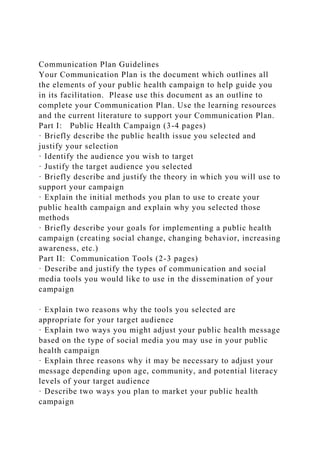
  • 26. engineers. The information considered, generated, or analyzed during a decision making process is stored in knowledge repositories in form of test-reports, FMEA, CAD-models, etc. What is need to be captured beside that, is information such as intention of activities, and argumentations for or against the considered alternatives. The information and their relation can be organized and managed by using a database. A so called ‘‘function board” controls collecting and managing the information between the repositories and data- base and enables the engineers to capture and access to this infor- mation through the user interface. In order to support retrieval of design rationale and reuse of design knowledge, a rationale representation should be able to address three questions [12] such as know-what: the solutions cre- ated, know-how: the courses of action, and know-why: the reason- ing process. It is essential to besides capturing the identified issues, problems, and developed solutions during the design process, cap- ture also how and why these solutions are created. Fig. 2 shows a UML model for representing design rationale. The Design Rationale and the Decision classes are central in the model. Design Rationale objects carry general information (text and picture based descrip-
  • 27. tions) regarding the concept or idea together with a set of Decision objects. The Decision objects carry information regarding decisions taken during the design process such as date, who took the deci- sion and, importantly, the argumentation behind the decision. The decision object also contains pointers to the information the decision and its argumentation was based on. Since that informa- tion is scattered these pointers have to be very specific, yet since that information is of many different types the pointers have to Design Ra�onale +Descrip�on +xhtml() Decision +Date +Responsible +Argumenta�on +xhtml() Statement +Local Path Suppor�ng Document +URL Requirements FMEA Test Report
  • 28. Discipline Model +Department +Owner Geometrical Model +URLs Product Design +Ar�cle Number +Name +Cost() Tooling Design +Tool ID +Machine ID +Cost() Assembly Assembly ID Weight() Part +Weight() +Part ID Feature +Type +Volume()
  • 30. 0..* 1 0..* 1 +Value 0..* 0..* 1 0..* 1 0..* 1 Fig. 2. Class diagram supporting capturing, structuring and accessing design rationale. M. Poorkiany et al. / Advanced Engineering Informatics 30 (2016) 522–536 527 be very general. In the proposed model, pointers to documents that are not related to CAD-models are called Statements. Statement objects capture information typically found in test-reports, lists of requirements and FMEA documents. (Note that the pointers tar- get sub-sets of the supporting documents, not the whole files.) Since decisions made during the product development process affect the geometry of the product to a great extent it is possible to make the Decision objects point to Assembly, Part, Feature, Parameter, and Entity objects in CAD-models. A decision may
  • 31. also affect the material selection of components of the product or the tooling and in such cases there are pointers to Material objects. Design rationale occurs all the time over the product life cycle and should be captured at its origin using the proposed class dia- gram which can be achieved by providing an integrated environ- ment. In such an environment the tools for capturing design rationale as well as representing it are integrated to software already used by the engineers. A great advantage of such an envi- ronment is that the designers can perform design tasks in different software and applications and concurrently capture design ratio- nale. Design rationale can be captured and represented in formats that the designers are already familiar and would prefer to work with. Besides using the software as representation tools, many com- panies would like to share their corporate design knowledge via the internal websites to make it accessible for geographically dis- persed team members. The Design Rationale objects and the Deci- sion objects have functionality to produce xhtml-fragments to make flexible web-pages that are generated on demand based on the captured design rationale and underlying information. The Discipline Model class is introduced to filter the design rationale between disciplines. Product Design and Tooling Design are both derived from the Discipline class in the model presented here, but more such classes could be introduced. A Tooling
  • 32. Design object is associated to at least one product design (which is the common case but one tool could be used to produce several com- ponents). A Product Design object is associated with all that is handed over from product designers to manufacturing engineers, including the rationale as shown in the class diagram, see Fig. 2. When design changes are to be done the related design rationale can be browsed in generated web-pages or accessed through the integrated design rationale environment to see what assemblies, parts, features, parameters, and geometrical entities it will affect in design itself but also on the tooling. The underlying decisions with all connected documents will also show up. Going in the other direction, i.e. when changing the tooling design, is also possible when using the proposed class diagram. Fig. 3 shows an example of a decision object and how it can be linked to feature and statement classes. A set of headings are defined in the decision class to provide a better and detailed under- standing not only about the final solution and the decision made, but also about the process of making the decision such as date, design members, and arguments for and against the alternatives (both selected and rejected ones). The statements and feature can be linked to the decision object but in a more specific way they can be linked to the exact headings in the decision object. 4. Case study To investigate the applicability of the proposed method and the class diagram a prototype system was developed in
  • 33. collaboration with a company. The selected company develops and manufac- tures customized products and accessories, such as roof racks and bike carriers, for different car models. The development pro- cess of a car’s roof rack was selected for more investigation. The company acts on the open market competing with car manufactur- ers and therefore gets no nominal data of car roofs. Instead, the engineers have to collect geometrical information about car roofs by measuring the actual car’s roof and develop the roof rack based on that geometrical information. The trend of selling new roof racks is highly related to the time a new car enters the market. A clamping roof rack is a rack used on cars without rails on the roof (i.e. the rack is standing on the roof and clamped around it Spreadsheet Plain text/picture CAD-model statement feature Statement statement
  • 34. …... Another representa�on format Decision • Date • Responsible • Argumenta�on • ... A roof rack without need for rail can be customized and adjusted to the new car by modifying two components, footpad and brackets, shown in the picture. In this project the design of footpad and bracket developed previously for car type xxxx was selected as base to adapt them according to new requirements. Fig. 3. The correlation between decision, statement and feature objects according to the UML-model. 528 M. Poorkiany et al. / Advanced Engineering Informatics 30 (2016) 522–536 where the doors are). Fig. 4 shows how a roof rack is attached to a car. The roof rack is developed in a way which enables the engi- neers to instead of developing a complete new roof rack for a new car, just design the two components called brackets and foot- pads in Fig. 4, and accordingly, adapt the roof rack to the new car. Fig. 4. A virtual model of roof rack. 4.1. Enabling capture, structure, and access to design rationale The development process of the footpad was selected as the case study. Collaboration and communication between the
  • 35. product designers and tooling designers is significant in the company in order to allow them to realize the downstream effects of their design activities. Access to design rationale explaining the reasons, arguments, and effects of decisions made for both footpad and tooling could support this collaboration and provide a better understanding of the design. The approach is based on the integration of SolidWorks, Word, Excel, and wiki pages. The reason of choosing different software was to represent the design rationale in different formats. Solid- Works was chosen as representative for 3D modeling, Microsoft Excel for rules definition and drawing tables, and Microsoft Word for specifications and textual usage were selected. Besides the soft- ware, wiki pages are chosen to record the decisions. Wiki is a type of content management tool and enables linking, navigation and searching the information. It allows the users to edit and form both the information and the structure to fit their purposes in an organic way. Free available sources and user friendly are the other benefits of using wikis. 18 wiki pages are created explaining a number of decisions. An information model, displayed in Fig. 5, was developed in order to form the principles of the introduced method. The infor- mation model consists of two types of classes; general and specific.
  • 36. The general classes comprise Design Rationale, Decision, and State- ment classes. The Statement class includes any of the software applications. The specific classes target the software applications, in this case Word, Excel and SolidWorks. It should be considered that the information model for the developed prototype is slightly different from the UML model presented in Fig. 2. Here, the geo- metrical model class is included in the statement class. When using the information model, the statement class carry information about where the actual design content is stored. These statements can be viewed as hyperlinks, which can point to a specific file on the hard drive or a web-page at a certain URL, but the statements are more specific than that, pointing to, for instance, a specific feature or a dimension in 3D-modeling software, a specific bookmark in a word processing document, or a certain range of cells in a spreadsheet. It is possible to extend the information model to target other software applications by implementing new types of specific classes, indicated with dashed lines in Fig. 5. Additionally, the decision class is used to cluster the statement objects that are related together. For exam- ple, some ranges of spread sheets, bookmarks in different textual documents, and some features in some geometrical models that have something to do with each other in a natural way can form a decision class. Such a group can be viewed and utilized as a multilateral hyperlink that makes it possible to go back and forth from one statement object to several others. So, for instance, when selecting a feature in a CAD-model that is targeted in a statement class, all other statement objects in that decision can
  • 37. be monitored to the user making it possible to jump to the con- nected workbook or spreadsheet entities, or other 3D-modeling entities. Fig. 5. The backbone information model in the prototype system. M. Poorkiany et al. / Advanced Engineering Informatics 30 (2016) 522–536 529 To make the decision classes meaningful, they are stored in Design Rationale objects that can contain a number of decisions that are somehow naturally connected to each other. By integrating the capture process with other design activities, the designers are able to record the design rationale wherever the need is raised. Access to the information can be strengthened by allowing the user browse and navigate across documents contain- ing design rationale. The suggestion is to provide a common user interface in each software that presents all the rationales, state- ments, and decisions (see Fig. 6). Hence, it is proposed to develop add-ins to the targeted software applications in a standardized way so that the users feel comfortable and recognize the system and the functions it stands for. In the standardized add-in user interface there should not only be functionality for monitoring available design rationales but also to connect the related statements. The user interface can facilitate the user to create a new design rationale, connect the statements
  • 38. together, and associate a wiki to the design rationale. Since the user interface is common for all the software and controlled by the function board, whenever a new design rationale is generated or a new link between the statements is created, all the activities are presented and the content of the windows is updated simulta- neously in all the software. The prototype system was developed in Microsoft.net environ- ment. It can be installed in form of extension to Word, Excel, and SolidWorks, however, it is possible to target more software if ben- eficial. The system connects SolidWorks, Excel and Word together. In order to embed the wiki into the system, the system allows the user to attach the URL address of a specific wiki page to a design rationale. The graphical user interface of the prototype system consists of three windows (task panes) added to each targeted software appli- cation, see Fig. 6 (screenshots of SolidWorks and Excel are pre- sented in Figs. 9 and 10). Two windows, called Design Rationales and Statements, are added to the right side of each software. The third window is named Decision which is shown at the bottom of the software. The properties of each window can be summarized as below:
  • 39. � The Design Rationale window edits and monitors all the design rationales regardless of which software they were first created in. This window shows the created design rationale and is con- stituted of two tabs named Active Selection and Browse. The Active Selection tab enables add, edit, or remove a design ratio- nale. It is also possible to attach an extra file, for instance, a wiki page to a design rationale. All these functions can be accessed by right clicking in the windows and selecting the desired func- tion. The Browse tab monitors all the available design rationales. � The Statements window allows to link the related statements together by forming groups. This window provides functionality to group the related statements together across different software. � The Decision window displays the decision (wiki page) attached to a design rationale. 4.2. Use case example In order to express the functionality of the prototype system an object diagram is created by showing two examples of decisions made in product and tooling design, see Fig. 7. Decision 1 is about changing the dimension of the footpad after testing the created prototype. This decision includes one statement in FMEA and one statement in CAD model. Decision 2 concerns applying changes in tooling design after changes occur in footpad design. This model is explained in the following sub-sections. Due to the company’s
  • 40. policy, the information presented in the following picture is fictive. 4.2.1. Product design An example is given to show how product designers are to work with the suggested system. This example targets the design pro- cess of the footpad. According to the requirements, two design alternatives are considered which after some evaluations a deci- sion is made on choosing one of the alternatives. A prototype of the selected alternative is created. The prototype is tested which indicates the need for performing some changes in the footpad design. Fig. 8 shows the created wiki page explaining the decision. It should be considered that this wiki is a sub-page of another page that provides explanation in a higher level of granularity about the product. A template including some headings is pro- vided to make it easy to record, understand and modify the con- tent. The headings are: article name/number, design date, design team members, intention and goals, assumptions, alternatives, and evaluations. As seen in Fig. 8, the page is not only to Software 1 Design Rationales Statements Decision I Software 2 Design
  • 41. Rationales Statements Decision II Design rationale I CAD-model Considered alternatives Test report and evaluations FM EA design Design rationale II CAD-model Validation test Manufacturing planni ng FMEA process Decision I ... Decision II ...
  • 42. Function Board Fig. 6. Enabling capture and access to design rationale via a common user interface. Design Rationale D1: Decision Responsible=xxxx Date= xxxx D2: Decision Name= Design of tooling Date= xxxx S3: Statement Name= Design memo S4: Statement File path= C:Working DirectoryTooling design Local path= [email protected][email protected] Name= Tooling upper plate S1: Statement Name= FMEA design Local path=ws.cell(A6:F6)
  • 43. Argumentation=change dimension of the rectangles due to being hard to mount the footpad Argumentation=change position of the cylinders due to change in footpad design File path= C:Working DirectoryTooling design Local path= bookmark Responsible=xxxx Description: Project nr. 1114:22 for developing a roof rack for car type xxxx-4 door sedan File path=C:Working DirectoryFootpad design S2: Statement File path=C:Working DirectoryFootpad design Local path= [email protected][email protected]@roof rack Name= Footpad feature
  • 44. Name= Design of footpad Fig. 7. An object diagram illustrating two examples of decisions in product design and tooling design. 530 M. Poorkiany et al. / Advanced Engineering Informatics 30 (2016) 522–536 address the decision that lead to the final solution but also explains how the solution is created and analyzed, if there were other alternatives considered but rejected, and evaluations of the solution. The evaluation section explains that the final design of the footpad is tested by making a prototype. However, it has been difficult to mount the prototype on the car. This can happen due to the level of accuracy in manufacturing equipment. After a discussion between the product design and tooling design, the designers agree upon changing the tolerance to 1. Fig. 8. A decision in footpad design recorded in wiki page. 1 For interpretation of color in Fig. 10, the reader is referred to the web version o this article. M. Poorkiany et al. / Advanced Engineering Informatics 30 (2016) 522–536 531 The change of the rectangles’ dimension should be applied in footpad CAD model. Fig. 9 shows the footpad designed in Solid- Works. First the corresponding feature for the big rectangles in the tree view in SolidWorks is selected. Next, a design rationale object called design of big rectangles is created by right clicking in
  • 45. the active selection window. By creating a design rationale object, the statements window is updated showing the path for the feature in SolidWorks. The user can assign a name to the decision, for instance, prototype evaluation in the statements window, indicating that this group of statements addresses a decision regarding proto- type evaluation. This allows the user to categorize the statements that address the same issue. Moreover, the user can assign a partic- ular wiki page or even a pdf-file as an attachment to the design rationale (shown in active selection window). In this example the wiki shown in Fig. 8 is attached to design of big rectangles. In addition, the change of the dimension in footpad design should be captured in FMEA. Fig. 10 shows a statement in the FMEA captured in Excel that targets certain cells addressing this issue. Since both SolidWorks and Excel are controlled by the func- tion board, the content of the user interface in Excel was updated when design of big rectangles was created in SolidWorks. Now, the user can select the corresponding cells in Excel, right click on the prototype evaluation in statements window and click on add statement. The statements window will be updated showing paths to two statements. So, a design rationale object is created called design of big rectangles which targets two statements: one a feature in SolidWorks, and one a range of cells in FMEA. The
  • 46. statements are now connected to each other which means if the user clicks on the rectangles in SolidWorks the corresponding cells in Excel docu- ment will be highlighted in blue1 and the other way around, by clicking on a cell in that row in Excel the rectangles in SolidWorks will be highlighted. This makes it easier for the users to find the par- ticular statement that they are looking for that is linked to the cur- rent statement they are clicking on. The wiki page that was attached to design of big rectangles is also f Fig. 9. The footpad modeled in SolidWorks. 532 M. Poorkiany et al. / Advanced Engineering Informatics 30 (2016) 522–536 shown in the decision window in Fig. 10. It can be maximize or opened separately if it is preferred. 4.2.2. Tooling design Decision 2 shown in Fig. 7 is explained in this section. The main process in manufacturing a footpad is using a press machine. A tooling is to be developed to be used in the press machine for form- ing the footpad. The tooling consists of plates and cylinders that are designed separately and then assembled together. The design team is agreed upon reuse of a tooling that was developed previ- ously for manufacturing a former footpad variant. Fig. 11 shows
  • 47. the wiki page created to record the decision. The page is created by following the same template as used in product design. Due to the changes in footpad design, the tooling needs to be modified. Two alternatives are considered and after a discussion the second alternative which suggests changing the positions of the cylinders in the upper plate is chosen. The arguments for and against each alternative is recorded in the wiki. When the decision is made, the changes should be performed in the CAD model. Fig. 12 shows the tooling modeled in SolidWorks. The upper plate is indicated by an arrow. The upper plate’s sketch is modified according to the decision and a design rationale object is created called upper plate targeting the new dimension. Further, the change is to be recorded in the design memo in order to inform the other engineers. Fig. 13 shows the design memo recorded in Word document. By opening up the document, all the created design rationales are shown in the user interface. Now, the user can select the lines that express the change, select the upper plate in design rationales window, right clicks on the cor- responding file path and select add statement. So, the dimension in SolidWorks is connected to the lines in Word. By clicking on the lines in Word, the plate in SolidWorks will be highlighted, or vice versa (some lines in Word are highlighted in gray in Fig. 13). The wiki page containing the information about the decision is
  • 48. also attached to the upper plate, shown in the decision window. The system allows the users to group a number of design ratio- nales together by mapping them into a virtual folder. For instance, Tooling is a folder containing three design rationales such as upper plate, press, and cylinder (see the Browse tab in Fig. 13). 4.3. Case study evaluation The prototype system was evaluated in the case company through workshops and an evaluation session. The product devel- opment manager, the chief engineer for racks, and a production engineer participated in the evaluation. After presenting the sys- tem, a number of questions were distributed to be answered by the participants. Overall, the participants affirmed the possibility to employ such a system into the design implementations in the company. They stated the great advantage of linking the related information (statements) across the software, especially between SolidWorks and Excel. It was acknowledged that such functionality would highly facilitate tracing the effected knowledge when updates are required across the product documentation in the company. Although the participants would like to test the prototype sys- tem in the organization across the broad in a larger scale, they are optimistic that the benefits would outbalance the efforts. However, maintenance of an additional system, and the need for learning and understanding the system by the users were the concerns
  • 49. stressed Fig. 10. The FMEA recorded in Excel. M. Poorkiany et al. / Advanced Engineering Informatics 30 (2016) 522–536 533 by the participants. Providing a view of the CAD model in Excel in order to be used by the practitioners who do not need to have access to SolidWorks, were the suggestions for further improvements. 5. Discussion A method to support capture, structure, and access to design rationale was introduced in this paper. The contribution of the pro- posed method to each of these processes is explained as follows. 5.1. Capturing design rationale In order to reduce the intrusion of capturing design rationale, it is suggested to embed capturing design rationale as closely in the design activities as possible. This can be achieved by enabling the users to capture the design rationale in the software that they are already using to do their work. Thus, the user does not need to open up an additional tool for the sole purpose of capturing the rationale. Since accomplishing the design activities entails using different independent software, integrating the software allow the users to capture the design rationale in a range of formats that the
  • 50. available software in the organization support. The suggestion for creating such integration is to implement extensible applications into the software to enable capturing the rationale in the appropriate soft- ware wherever the need is raised. The application should have the ability to target the information in each software and connect the related information together in different software. An application with the intention of presenting the information in an explicit way (in this study wiki was used to represent information in form of text and picture) could also be embedded in this environment in order to record the argumentations that is usually not captured in the statements, for instance, the rejected design alternatives. One limitation in the introduced method is the lack of a shared base to allow the engineers to record the tacit knowledge from their minds in a common form that is understandable for all other users, not just some texts and comments that can be understood only by the persons who have recorded them. 5.2. Structuring design rationale Structure is achieved by the proposed class model as presented in the UML diagram and the template provided for the wiki pages. The decision class presented in Fig. 2 makes it possible to group and map the related statements across different software. This facilitates traceability to pursue the effected information when a
  • 51. part of the knowledge needs to be updated. What needs to be explored more is the granularity of the recorded design rationales and the ability to structure and repre- sent the information in different layers of details as discussed in Section 2.2. Fig. 11. A decision in tooling design recorded in wiki page. 534 M. Poorkiany et al. / Advanced Engineering Informatics 30 (2016) 522–536 5.3. Access to design rationale Access to design rationale can be strengthened by enabling the user to quickly list, view, and browse the design rationales across the documents. Providing instant access would more likely encour- age the designers to capture the rationale, because they know the information can benefit them or their colleagues now, not just dur- ing the future design projects. The suggestion is to provide a user interface to facilitate intuitive human-computer interaction. This can be supported by developing extensible applications integrated in the software that the designers are using, to make the informa- tion instantly accessible whenever it is required. However, a bot- tleneck in such user interfaces is to keep their efficiency and simplicity when the number of the statements and decisions are
  • 52. increasing. The proposed method was examined by implementing a proto- type system in the case company. One request from the designers was to find and expose the related design knowledge in one soft- ware when changes occur in the content of the design knowledge in another software. Therefore, access to the design rationales and statements through a common user interface was recognized as a big advantage of the method in order to fulfil the designers’ needs at the company. The literature review of design rationale systems provided in Section 2, presents some similar contributions to this study. For instance, providing annotations to explicitly comment an argu- ment in a CAD software, or hyperlinks to knowledge sources. What is new in this study is enabling the users to simultaneously work in an integrated environment of software in which the design ratio- nale statements are interconnected in a way making it possible to go back and forth. For example, when selecting a cell in Excel the system notifies the user about other interconnected Excel cells, but also interconnected SolidWorks-features, word bookmarks, or wiki-pages. Additionally, if found in random access memory the interconnected entities will interactively highlight in its software. Currently, the prototype system has been tested on local com-
  • 53. puters. Therefore, it is not possible to exchange the information across networks. Centralizing the prototype system on a server and providing a database enables the engineers to communicate through interactive selections. Such an architecture would facili- tate collaboration and communication among a group of engineers especially when one performs an activity in one software and the other one can simultaneously see the activity and trace the Fig. 12. The tooling modeled in SolidWorks. Fig. 13. The design memo recorded in Word. M. Poorkiany et al. / Advanced Engineering Informatics 30 (2016) 522–536 535 effected knowledge in another software. This allows the engineers to assimilate the relevant cues and examine the potential downstream effects of their decisions even if the engineers are not co-located. 536 M. Poorkiany et al. / Advanced Engineering Informatics 30 (2016) 522–536 6. Conclusion and future work The focus of the research presented in this paper was on captur- ing, structuring, and accessing design rationale by integration of different software that are commonly used in the design process. The research resulted in a method applicable to both product
  • 54. design and tooling design. The proposed method based on the introduced class diagram was tested in a case company developing car roof racks. It is essential that the product design conforms to the constraints and properties of the intended manufacturing pro- cesses, therefore, a close collaboration and support for knowledge exchange between product design and tooling design is important. The feedback from the evaluation sessions and workshops in the case company shows the potential benefits of the presented method. Some of the advantages of the method are: integrating design rationale capture and access in the design implementations, representing design rationale in a proper format, and structuring the related statements into a decision. The practitioners at the case company found the proposed method helpful and that it could con- siderably save time and cost during developing new product vari- ants. However, at this early stage, it is not possible to quantify the benefits of the method or if the benefits outbalance the effort. There are still issues remain regarding the consistency, quality, and version control of the captured design rationale and documentation. From an industrial perspective the implementation and integra- tion of a system is a critical process and of high importance. Under- standing the relationships between the system and its external environment is essential to establish system functionalities and
  • 55. the way the system communicates with other tools and systems. Actions are required to ensure system alignment with the com- pany’s IT infrastructure, more specifically, elaborating on multi- platform solutions such as Linux, IOS, and windows. Additionally, the applicability of the method for a group of users, the communi- cation among the users and the maintenance of the system realiza- tion are issues for future research. Acknowledgments This research was a part of the IMPACT project financially sup- ported by KK Foundation in Sweden. The authors gratefully acknowledge Thule Sweden for technical guidance regarding the case product and for being enthusiastic about the proposed method. References [1] D.M. Anderson, Design for Manufacturability & Concurrent Engineering: How to Design for Low Cost, Design in High Quality, Design for Lean Manufacture, and Design Quickly for Fast Production, CIM Press, 2004. [2] M. Bonev, Enabling mass customization in engineer-to-order industries, A multiple case study analysis on concepts, methods and tools, DTU Management Engineering, 2015. [3] S. Kim, R. Bracewell, K. Wallace, Improving design reuse using context, in:
  • 56. ICED07: 16th International Conference on Engineering Design, 2007. [4] J. Lee, K.-Y. Lai, What’s in design rationale? Hum. Comput. Interact. 6 (3–4) (1991) 251–280. [5] A. Tang et al., A survey of architecture design rationale, J. Syst. Softw. 79 (12) (2006) 1792–1804. [6] A. Tang, Y. Jin, J. Han, A rationale-based architecture model for design traceability and reasoning, J. Syst. Softw. 80 (6) (2007) 918– 934. [7] A.H. Dutoit et al., Rationale management in software engineering: concepts and techniques, Springer, 2006, 1–48. [8] S. Szykman, R.D. Sriram, W.C. Regli, The role of knowledge in next-generation product development systems, J. Comput. Inform. Sci. Eng. 1 (1) (2001) 3–11. [9] J. Lee, Design rationale systems: understanding the issues, IEEE Intell. Syst. 12 (3) (1997) 78–85. [10] J. Johansson, M. Poorkiany, F. Elgh, Design rationale management—a proposed cloud solution, in: Moving Integrated Product Development to Service Clouds in the Global Economy, 2014. [11] S.K. Chandrasegaran et al., The evolution, challenges, and future of knowledge
  • 57. representation in product design systems, Comput. Aided Des. (2012). [12] H. Wang, A.L. Johnson, R.H. Bracewell, The retrieval of structured design rationale for the re-use of design knowledge with an integrated representation, Adv. Eng. Inform. 26 (2) (2012) 251–266. [13] B. Hicks et al., A framework for the requirements of capturing, storing and reusing information and knowledge in engineering design, Int. J. Inform. Manage. 22 (4) (2002) 263–280. [14] J. Johansson, A flexible design automation system for toolsets for the rotary draw bending of aluminium tubes, in: ASME, American Society of Mechanical Engineers, New York, United States, 2007. [15] J. Johansson, D.C. Brown, Automated Computer Systems for Manufacturability Analyses and Tooling Design: Applied to the Rotary Draw Bending Process, School of Engineering, Jönköping University, 2011. [16] R. Owen, I. Horváth, Towards product-related knowledge asset warehousing in enterprises, in: Proceedings of the 4th International Symposium on Tools and Methods of Competitive Engineering, Hubei, China, 2002. [17] F. Elgh, Modeling and management of product knowledge in an engineer-to- order business model, in: ICED11: 18th International Conference on
  • 58. Engineering Design, 2011. [18] R. Bracewell et al., Capturing design rationale, Comput. Aided Des. 41 (3) (2009) 173–186. [19] W.C. Regli et al., A survey of design rationale systems: approaches, representation, capture and retrieval, Eng. Comput. 16 (3–4) (2000) 209–235. [20] Y. Nomaguchi, K. Fujita, Knowledge representation framework for interactive capture and management of reflection process in product concepts development, Adv. Eng. Inform. 27 (4) (2013) 537–554. [21] M. Poorkiany, J. Johansson, F. Elgh, A case study on implementing design automation: identified issues and solution for documentation, in: 20th ISPE International Conference on Concurrent Engineering, 2013. [22] K.M. Saridakis, A.J. Dentsoras, Soft computing in engineering design—a review, Adv. Eng. Inform. 22 (2) (2008) 202–221. [23] S. Murthy, D. Maier, SPARCE. Superimposed Pluggable Architecture for Contexts and Excerpts, Technical Report CSE-03-010, Maseeh College of Engineering and Computer Science, 2003. [24] S. Murthy et al., Putting integrated information in context: superimposing conceptual models with SPARCE, Proceedings of the first
  • 59. Asian-Pacific Conference on Conceptual Modelling, vol. 31, 2004. [25] R. Bracewell et al., In: ICED07: 16th International Conference on Engineering Design, Paris, France. [26] W. Kunz, H.W. Rittel, Issues as Elements of Information Systems, vol. 131, Institute of Urban and Regional Development, University of California Berkeley, California, 1970. [27] Y. Zhang et al., A semantic representation model for design rationale of products, Adv. Eng. Inform. 27 (1) (2013) 13–26. [28] O. Hisarciklilar, J.-F. Boujut, An annotation based approach to support design communication, in: ICED07: 16th International Conference on Engineering Design, Paris, France, 2007. [29] S. Sandberg et al., Supporting engineering decisions through contextual, model-oriented communication and knowledge-based engineering in simulation-driven product development: an automotive case study, J. Eng. Des. 24 (1) (2013) 45–63. [30] M. Lundin, Computer-Aided Product Development: Using computer-aided technologies for efficient design capture and representation for reuse, Luleå University of Technology, 2015.
  • 60. [31] F. Elgh, M. Cederfeldt, Documentation and management of product knowledge in a system for automated variant design: a case study, in: New World Situation: New Directions in Concurrent Engineering, Springer, 2010, pp. 237– 245. [32] J. Burge, D.C. Brown, Design Rationale Types and Tools, AI in Design Group, 1998. http://refhub.elsevier.com/S1474-0346(16)30172-0/h0005 http://refhub.elsevier.com/S1474-0346(16)30172-0/h0005 http://refhub.elsevier.com/S1474-0346(16)30172-0/h0005 http://refhub.elsevier.com/S1474-0346(16)30172-0/h0005 http://refhub.elsevier.com/S1474-0346(16)30172-0/h0010 http://refhub.elsevier.com/S1474-0346(16)30172-0/h0010 http://refhub.elsevier.com/S1474-0346(16)30172-0/h0010 http://refhub.elsevier.com/S1474-0346(16)30172-0/h0010 http://refhub.elsevier.com/S1474-0346(16)30172-0/h0015 http://refhub.elsevier.com/S1474-0346(16)30172-0/h0015 http://refhub.elsevier.com/S1474-0346(16)30172-0/h0015 http://refhub.elsevier.com/S1474-0346(16)30172-0/h0020 http://refhub.elsevier.com/S1474-0346(16)30172-0/h0020 http://refhub.elsevier.com/S1474-0346(16)30172-0/h0025 http://refhub.elsevier.com/S1474-0346(16)30172-0/h0025 http://refhub.elsevier.com/S1474-0346(16)30172-0/h0030 http://refhub.elsevier.com/S1474-0346(16)30172-0/h0030 http://refhub.elsevier.com/S1474-0346(16)30172-0/h0040 http://refhub.elsevier.com/S1474-0346(16)30172-0/h0040 http://refhub.elsevier.com/S1474-0346(16)30172-0/h0045 http://refhub.elsevier.com/S1474-0346(16)30172-0/h0045 http://refhub.elsevier.com/S1474-0346(16)30172-0/h0050 http://refhub.elsevier.com/S1474-0346(16)30172-0/h0050
  • 61. http://refhub.elsevier.com/S1474-0346(16)30172-0/h0050 http://refhub.elsevier.com/S1474-0346(16)30172-0/h0050 http://refhub.elsevier.com/S1474-0346(16)30172-0/h0055 http://refhub.elsevier.com/S1474-0346(16)30172-0/h0055 http://refhub.elsevier.com/S1474-0346(16)30172-0/h0060 http://refhub.elsevier.com/S1474-0346(16)30172-0/h0060 http://refhub.elsevier.com/S1474-0346(16)30172-0/h0060 http://refhub.elsevier.com/S1474-0346(16)30172-0/h0065 http://refhub.elsevier.com/S1474-0346(16)30172-0/h0065 http://refhub.elsevier.com/S1474-0346(16)30172-0/h0065 http://refhub.elsevier.com/S1474-0346(16)30172-0/h0070 http://refhub.elsevier.com/S1474-0346(16)30172-0/h0070 http://refhub.elsevier.com/S1474-0346(16)30172-0/h0070 http://refhub.elsevier.com/S1474-0346(16)30172-0/h0070 http://refhub.elsevier.com/S1474-0346(16)30172-0/h0075 http://refhub.elsevier.com/S1474-0346(16)30172-0/h0075 http://refhub.elsevier.com/S1474-0346(16)30172-0/h0075 http://refhub.elsevier.com/S1474-0346(16)30172-0/h0075 http://refhub.elsevier.com/S1474-0346(16)30172-0/h0085 http://refhub.elsevier.com/S1474-0346(16)30172-0/h0085 http://refhub.elsevier.com/S1474-0346(16)30172-0/h0085 http://refhub.elsevier.com/S1474-0346(16)30172-0/h0085 http://refhub.elsevier.com/S1474-0346(16)30172-0/h0090 http://refhub.elsevier.com/S1474-0346(16)30172-0/h0090 http://refhub.elsevier.com/S1474-0346(16)30172-0/h0095 http://refhub.elsevier.com/S1474-0346(16)30172-0/h0095 http://refhub.elsevier.com/S1474-0346(16)30172-0/h0100 http://refhub.elsevier.com/S1474-0346(16)30172-0/h0100 http://refhub.elsevier.com/S1474-0346(16)30172-0/h0100 http://refhub.elsevier.com/S1474-0346(16)30172-0/h0105 http://refhub.elsevier.com/S1474-0346(16)30172-0/h0105 http://refhub.elsevier.com/S1474-0346(16)30172-0/h0105 http://refhub.elsevier.com/S1474-0346(16)30172-0/h0105 http://refhub.elsevier.com/S1474-0346(16)30172-0/h0110 http://refhub.elsevier.com/S1474-0346(16)30172-0/h0110 http://refhub.elsevier.com/S1474-0346(16)30172-0/h0115
  • 62. http://refhub.elsevier.com/S1474-0346(16)30172-0/h0115 http://refhub.elsevier.com/S1474-0346(16)30172-0/h0115 http://refhub.elsevier.com/S1474-0346(16)30172-0/h0115 http://refhub.elsevier.com/S1474-0346(16)30172-0/h0120 http://refhub.elsevier.com/S1474-0346(16)30172-0/h0120 http://refhub.elsevier.com/S1474-0346(16)30172-0/h0120 http://refhub.elsevier.com/S1474-0346(16)30172-0/h0120 http://refhub.elsevier.com/S1474-0346(16)30172-0/h0130 http://refhub.elsevier.com/S1474-0346(16)30172-0/h0130 http://refhub.elsevier.com/S1474-0346(16)30172-0/h0130 http://refhub.elsevier.com/S1474-0346(16)30172-0/h0130 http://refhub.elsevier.com/S1474-0346(16)30172-0/h0135 http://refhub.elsevier.com/S1474-0346(16)30172-0/h0135 http://refhub.elsevier.com/S1474-0346(16)30172-0/h0145 http://refhub.elsevier.com/S1474-0346(16)30172-0/h0145 http://refhub.elsevier.com/S1474-0346(16)30172-0/h0145 http://refhub.elsevier.com/S1474-0346(16)30172-0/h0145 http://refhub.elsevier.com/S1474-0346(16)30172-0/h0150 http://refhub.elsevier.com/S1474-0346(16)30172-0/h0150 http://refhub.elsevier.com/S1474-0346(16)30172-0/h0150 http://refhub.elsevier.com/S1474-0346(16)30172-0/h0150 http://refhub.elsevier.com/S1474-0346(16)30172-0/h0155 http://refhub.elsevier.com/S1474-0346(16)30172-0/h0155 http://refhub.elsevier.com/S1474-0346(16)30172-0/h0155 http://refhub.elsevier.com/S1474-0346(16)30172-0/h0155 http://refhub.elsevier.com/S1474-0346(16)30172-0/h0155 http://refhub.elsevier.com/S1474-0346(16)30172-0/h0160 http://refhub.elsevier.com/S1474-0346(16)30172-0/h0160 http://refhub.elsevier.com/S1474-0346(16)30172- 0/h0160Capturing, structuring and accessing design rationale in integrated product design and manufacturing processes1 Introduction2 Frame of reference2.1 Design knowledge2.2 Design rationale; motivations and challenges2.3 Related work2.4 Knowledge gap3 Constructs for design rationale capture, structure, and access4 Case study4.1 Enabling capture, structure, and access to design rationale4.2 Use case
  • 63. example4.2.1 Product design4.2.2 Tooling design4.3 Case study evaluation5 Discussion5.1 Capturing design rationale5.2 Structuring design rationale5.3 Access to design rationale6 Conclusion and future workAcknowledgmentsReferences 10/24/2016 Quantifying Design for Manufacturability https://www.mdtmag.com/article/2012/06/quantifying-design-m anufacturability 1/11 Wed, 06/06/2012 - 8:56am DEEPER INSIGHTS A New Mindset in Product Design: 3D printing can help Quantifying Design for Manufacturability by John Rokus It was the scientist Lord Kelvin who said, "When you can measure what you are speaking about, and express it in numbers, you know something about it; but when you cannot measure it, when you cannot express it in numbers, your knowledge is of a meager and unsatisfactory kind.” So, if you are among those in the medical device industry who are struggling to keep DFM alive and well within your organization, or you plan to kick off a DFx initiative, this article is for you.
  • 64. While Google and Wikipedia were both fruitless in providing a definitive answer as to the origins of Design for Manufacturability (DFM), it does not diminish the profound impact the process can have on real profitability. The vast majority of medical device engineers and engineering managers are familiar with DFM or 7 http://whitepapers.ecnmag.com/20151028_stratasys_product_de sign_3d_printing_wp/?cmpid=regwallcontent&utm_source=Dee per%20Insights&__hstc=150617065.06d7738c5c3e1f95e2e6bd5 d66f7df23.1476771473140.1476845573913.1477358529849.5& __hssc=150617065.1.1477358529849&__hsfp=1710401753 http://whitepapers.ecnmag.com/20151028_stratasys_product_de sign_3d_printing_wp/?cmpid=regwallcontent&utm_source=Dee per%20Insights&__hstc=150617065.06d7738c5c3e1f95e2e6bd5 d66f7df23.1476771473140.1476845573913.1477358529849.5& __hssc=150617065.1.1477358529849&__hsfp=1710401753 10/24/2016 Quantifying Design for Manufacturability https://www.mdtmag.com/article/2012/06/quantifying-design-m anufacturability 2/11 printing can help bring products to market faster Design For “x” (DFx) concepts but
  • 65. relatively few have implemented methods to measure the effectiveness of their efforts. Consider the following formula: Price = Cost + Profit. In a noncompetitive environment, a company may get away with assuming Cost and Profit are fixed amounts by which they determine the Price they will charge for their product. Now consider this version of the formula; Profit = Price – Cost, where Price is fixed by what the market will bear and Cost is the true variable by which Profit can be maximized. Designing for manufacturability is an essential core competency for any design or manufacturing company that is seeking customers in a competitive environment because it supports a holistic approach to cost and profitability. Think of it as lean design if you’re in a company practicing Lean. It helps analyze designs and make decisions that lower overall costs, not just product costs. Combining DFM with new product development will yield significant cost reductions by: Increasing manufacturing throughput Reducing damage rates of products and people Obtaining higher first time quality Streamlining logistics Faster development and delivery of new products. When to apply DFM http://whitepapers.ecnmag.com/20151028_stratasys_product_de sign_3d_printing_wp/?cmpid=regwallcontent&utm_source=Dee per%20Insights&__hstc=150617065.06d7738c5c3e1f95e2e6bd5 d66f7df23.1476771473140.1476845573913.1477358529849.5& __hssc=150617065.1.1477358529849&__hsfp=1710401753
  • 66. 10/24/2016 Quantifying Design for Manufacturability https://www.mdtmag.com/article/2012/06/quantifying-design-m anufacturability 3/11 Figure-1 Figure 1. Influencing Product Cost Design engineering will often cry, “It’s too early, the design isn’t far enough along for critique” only to find themselves later saying, “Oh, we should have done this six months ago because the tooling has already been cut” Most DFM experts will agree that approximately 65% of the total product cost will be dictated by the specified materials and required labor to assemble with only 5% accounted for in product design efforts. Ironically, the tiny proportion of the product cost consumed by design engineering will account for 70% of influence on the total product cost. A quick study of Figure 1 will highlight the importance of product design on product cost relative to its financial investment over the life of the product. So, with this realization, it becomes apparent that we must initiate DFM efforts earlier than intuition would suggest. Most organizations can accept this suggestion as long as the effort is type cast correctly and void of process ambiguity. This brings us to our first and most fundamental way to quantify our efforts through Conceptual DFM analysis and “The Part Value Challenge”.
  • 67. 10/24/2016 Quantifying Design for Manufacturability https://www.mdtmag.com/article/2012/06/quantifying-design-m anufacturability 4/11 Conceptual DFM What is it? – Conceptual DFM helps analyze the design concept through the part value challenge but it also facilitates other high level discussion that is design related but often times not discussed within new product development teams as early as it should be in order to maximize manufacturing, procurement and quality systems. When do we do it? – After customer requirements are gathered and before any significant amount of CAD work starts. Who should facilitate? - Project Manager or Design Engineer Does it have to be done on the entire assembly? – No, conceptual DFM analysis sessions can be broken down to smaller subassemblies. Especially in the case where some parts of the design are further along than others. Who should attend? Design Engineering Manufacturing Engineer Quality Procurement Suppliers as appropriate What should be brought to the meeting? 1. Any tangible product or products that will help visualize the concept design. 2. Customer requirements
  • 68. Function specific questions to be asked: Manufacturing: Are we designing in parts or processes that will require unfamiliar equipment or methods? If so, does the project plan incorporate related milestones to bring the equipment in and get it and it's processes validated? What fixtures or assembly aids will be required in assembly? Can we design them out? Procurement: Are we designing in any parts with lead times longer 10/24/2016 Quantifying Design for Manufacturability https://www.mdtmag.com/article/2012/06/quantifying-design-m anufacturability 5/11 than xx weeks> Are any of the parts single sourced? What would it take to make them dual sourced? Are we designing in any parts with risk of going obsolete within the product life cycle? Quality - Considering other similar products, what quality or reliability issues stand out that need to be addressed or avoided on this new design? Test Engineering - Do we have a concept for end of line production testing and will it comply with internal best practices for cycle time and repeatability? Part Value Challenge
  • 69. Figure-2 Figure 2.Original Door Design The intent of the part value challenge is to provide a high level assessment of the parts intended to be used in the makeup of the product. This tool is used to help safeguard against putting hours of detail design work into a concept that is way off the mark in terms of being DFM friendly. Here’s how it works. Conceptually or literally, the designer creates a bill of material to the best of his ability (actual piece part dimensions may be unknown but material, quantity and basic description will suffice). The DFM team evaluates each part against predetermined criteria and labels each part good or bad. Calculating the ratio of good parts to the total number of parts results in a metric titled: Design Efficiency. If the 10/24/2016 Quantifying Design for Manufacturability https://www.mdtmag.com/article/2012/06/quantifying-design-m anufacturability 6/11 design efficiency is less than 30%, stop the current design, develop a new concept and reanalyze. For printed circuit board components, we ask the following questions and if the answer is yes to any of these questions then the part is considered bad. 1. Can the part’s function be combined within other parts or components?
  • 70. 2. Does the component require manual soldering? 3. Can the component utilize surface mount technology? Note: wires, threaded fasteners and loose interconnects are always candidates for elimination. For parts other than circuit boards, the following questions can be used: 1. Does the part have to move? 2. Does the part have to be a fundamentally different material? Individual companies who experiment with the part value challenge will often derive a set of customized questions to better serve their industry and tribal knowledge of design elements that have hurt them in the past Conceptual DFM deliverables: Design Efficiency %......Go or no go decision on the current concept (Design efficiency less than 30% requires fundamental redesign) List of ideas and action items to be followed up on in order to improve manufacturability, testability, reliability, serviceability, quality, procurement and mistake proofing, etc. Practical DFM What is it?—A workshop that applies a method for analyzing the parts and associated assembly operations in an attempt to apply standardized penalty points to the design so that a design team can: Use the scores to compare different design alternatives
  • 71. 10/24/2016 Quantifying Design for Manufacturability https://www.mdtmag.com/article/2012/06/quantifying-design-m anufacturability 7/11 Figure-3 Figure 3. DFM Door Design Establish benchmarks and “target” design scores for similar designs in the future Think holistically and get all of the benefit from the design review instead of cherry picking a few good ideas. Stimulate creative thinking Heighten the design engineers’ awareness of manufacturing problems and make manufacturing engineers aware of functional problems The scoring system is organized into six categories. Each category contains a set of related penalties with pre-defined descriptions and points to be applied when applicable. 1. Pick-up Part 2. Part to Operator Interface 3. Part to Part Interface 4. Tools 5. Operations 6. Fastening For example, every part that has to be picked up prior to being added to the assembly must be assessed for its Pick-up Part score. A part requiring one hand to pick it up gets two points. A two hand pick-up gets 3 points and parts having to use any sort of assist device is burdened with 30 penalty points. All
  • 72. parts are analyzed with all six categories until a cumulative score is obtained for the entire assembly. 10/24/2016 Quantifying Design for Manufacturability https://www.mdtmag.com/article/2012/06/quantifying-design-m anufacturability 8/11 In addition to this penalty score, it is highly recommended to capture or estimate additional metrics such as labor associated with each assembly step, number of assembly steps, number of parts, number of “good” parts, number of fasteners and the number of opportunities for incorrect assembly (Poka Yoke issues). How do you do it? – While software is available from more than one supplier, it is possible to develop your own methodology and use Excel, Visio or plotter paper and sticky notes to document the scores for each part and category. How long does it last? –Workshops can last several hours, depending on the complexity of the assembly and the experience of the team. It is not unusual to spend three hours to score a design and 1 hour to brainstorm and prioritize DFM improvements. When to do it? – Practical DFM can take place any time after the conceptual session as long as the window for design changes is open. What preparation is required? – In particular, the manufacturing and design engineers use of concurrent engineering prior to the Practical DFM session should have allowed the manufacturing engineer to developed a
  • 73. preliminary manufacturing plan inclusive of process steps broken down to the piece part level, a list of tools and fixtures required in each step and assumptions for fastening methods if they are not already defined. Practical DFM example Consider the simple compartment door design shown in figure 2. Now consider its potential for redesign as shown in figure 3. In this example, the proposed design accomplishes several key DFM objectives: Reduction in the overall part count Reduced assembly labor Reduction for incoming inspection 10/24/2016 Quantifying Design for Manufacturability https://www.mdtmag.com/article/2012/06/quantifying-design-m anufacturability 9/11 Reduction in the number of suppliers Reduction in the number of opportunities for operator assembly error Elimination of threaded fasteners Elimination of a tool required for assembly Elimination of part types with potential to rattle A typical format for summarizing the results and facilitating decision making is shown in table 1. The table provides a simplified quantitative comparison the original and proposed
  • 74. designs. While most of the entries are self-explanatory, notice the entries for Quality Burden. In some cases this is a subjective number but in many cases, a company will have historical quality records to substantiate the cost of poor quality. table1 table1 Table 1.Executive DFM Summary Summary: The beauty of DFM metrics is in its ability to help communicate several cost variables instead of focusing on individual piece part costs. Manufacturing engineers and Operations managers need a way to quantify their hidden factories that are negatively impacted by designs that are all too often thrown over the wall with little DFM applied. A final product design is essentially a life sentence to the assemblers and all those who support the product in production. New product development teams must accept the responsibility as the stewards of all those who build and support the product. This is one of those rare opportunities we have to satisfy the worker and Wall Street at the same time. The author would like to give a special thanks to Munro & Associates, Inc. for allowing the reproduction of a portion of their training material including the structured methodology 10/24/2016 Quantifying Design for Manufacturability https://www.mdtmag.com/article/2012/06/quantifying-design-m anufacturability 10/11
  • 75. for calculating the design efficiency and the method described to score an entire assembly. John Rokus was formerly Vice President of Continuous Improvement for Micro Power Electronics, Inc. A subsidiary of Electrochem Solution s, Inc., Micro Power supplies custom battery systems to the portable medical, handheld Automatic Identification and Data Collection (AIDC) and commercial military markets. Micro Power is ISO 13485 and 9001:2008 certified, as well as ITAR registered. RELATED READS 5 Challenges of Getting Validation Right for Medical Molding and How to Overcome Them New NIST Test
  • 76. Bed Makes The 'Digital Thread' Accessible Precision Molded Parts Deliver Drug Compatibility, Purity and Stability Industrial 3D Printing Translates Breakthroughs into Lifesaving Technologies on University 7 http://www.mdtmag.com/article/2015/10/5-challenges-getting- validation-right-medical-molding-and-how-overcome- them?cmpid=horizontalcontent http://www.ecnmag.com/news/2016/10/new-nist-test-bed- makes-digital-thread- accessible?cmpid=horizontalcontent&__hstc=150617065.06d77
  • 77. 38c5c3e1f95e2e6bd5d66f7df23.1476771473140.1476845573913 .1477358529849.5&__hssc=150617065.1.1477358529849&__hs fp=1710401753 http://www.mdtmag.com/news/2016/06/precision-molded-parts- deliver-drug-compatibility-purity-and- stability?cmpid=horizontalcontent http://www.mdtmag.com/article/2015/12/industrial-3d-printing- translates-breakthroughs-lifesaving-technologies-university- budget?cmpid=horizontalcontent http://www.micro-power.com/ http://www.mdtmag.com/article/2015/10/5-challenges-getting- validation-right-medical-molding-and-how-overcome- them?cmpid=horizontalcontent http://www.ecnmag.com/news/2016/10/new-nist-test-bed- makes-digital-thread- accessible?cmpid=horizontalcontent&__hstc=150617065.06d77 38c5c3e1f95e2e6bd5d66f7df23.1476771473140.1476845573913 .1477358529849.5&__hssc=150617065.1.1477358529849&__hs fp=1710401753 http://www.mdtmag.com/news/2016/06/precision-molded-parts- deliver-drug-compatibility-purity-and- stability?cmpid=horizontalcontent http://www.mdtmag.com/article/2015/12/industrial-3d-printing- translates-breakthroughs-lifesaving-technologies-university- budget?cmpid=horizontalcontent
  • 78. 10/24/2016 Quantifying Design for Manufacturability https://www.mdtmag.com/article/2012/06/quantifying-design-m anufacturability 11/11 Breakthroughs into Lifesaving Technologies on University Budget High-Intensity Ultrasound Energy Used to Here's How to Convince the Brain that ALSO ON MEDICAL DESIGN TECHNOLOGY 0 Comments Medical Design Technology Share⤤ Sort by Best Start the discussion… Be the first to comment. http://www.mdtmag.com/article/2015/12/industrial-3d-printing-
  • 79. translates-breakthroughs-lifesaving-technologies-university- budget?cmpid=horizontalcontent http://disq.us/url?url=https%3A%2F%2Fwww.mdtmag.com%2F news%2F2016%2F08%2Fhigh-intensity-ultrasound-energy- used-treat- hypertension%3ANT4uoKOm70snpSzliJEC1PPMkVk&imp=6qjl fed2fg19gj&prev_imp&forum_id=1388198&forum=mdtmag&thr ead_id=747189181&thread=5040728281&zone=thread&area=bo ttom&object_type=thread&object_id=5040728281 http://disq.us/url?url=https%3A%2F%2Fwww.mdtmag.com%2F article%2F2016%2F09%2Fheres-how-convince-brain- prosthetic-legs-are- real%3AIYfxTfqZ1nEaAnJVfQQnfj30xdg&imp=6qjlfed2fg19gj &prev_imp&forum_id=1388198&forum=mdtmag&thread_id=74 7189181&thread=5141148194&zone=thread&area=bottom&obje ct_type=thread&object_id=5141148194 https://disqus.com/home/forums/mdtmag/ https://disqus.com/home/inbox/ Copyright © 1999. All rights reserved.
  • 80. Copyright © 1999. All rights reserved. Copyright © 1999. All rights reserved. Copyright © 1999. All rights reserved. ORIGINAL ARTICLE Detecting re-design area for increasing manufacturability of drilling and three-axis pocketing operations Hesam Samarghandy & Ye Li Received: 12 October 2012 /Accepted: 19 April 2013 /Published online: 10 May 2013 # Springer-Verlag London 2013 Abstract The intensive competition has forced the
  • 81. manufacturing industry to improve product quality and pro- duction efficiency, and meanwhile reduce production cost. Detecting potential manufacturability problems in early de- sign stages would prevent unnecessary cost involved in re- work and/or re-design activities at later manufacturing stages. This paper presents an algorithm for determining re-design areas to feedback the designer when the design model involves machining holes and pockets using a three- axis computer numerical control machine. The algorithm takes into account the various sizes of tools and tool holders, and therefore allows a designer to test the manufacturability of their available cutters on their design models. A color- based obstacle-detecting method, based on layer-slicing of re-design areas, helps a designer to re-evaluate a design model for increasing manufacturability. Practical examples are provided as the output of the process. Keywords Re-design . DFM (design for manufacturing) . Visibility . Manufacturability . Obstacle feature 1 Introduction Currently, there is an intensive competition among manu- facturers to obtain production processes with increased pro-
  • 82. ductivity, quality and reduced costs and time. This competition is significantly dependent on the effectiveness of product design. It has been reported that 70–80 % of product costs are directly affected by product design [1–3]. On the other hand, it has been shown that almost 90 % of the designers do not have deep understanding of manufacturing processes [4]. Therefore, it will be necessary to make a good connection between designers and manufacturers. In order to close this gap, design for manufacturability (DFM) has been developed since 1970s [5]. By associating design with manufacturing, DFM is able to avoid design defects in manufacturing stages, and therefore leads to reduced cost and production time that may be incurred in the forms of defects and re-work. With DFM implemented, design models are continuously evaluated and revised from early design stages so that the design problems can be minimized prior to manufacturing. This has made DFM well received in both industry and academia. In order to make design models manufacturable, one solu- tion is to define manufacturing features and then design by those predefined manufacturing features. However restricting designers with predefined manufacturing features tend to nar- row down the designers’ creativity and freedom [4, 6, 7]. For