Generic preoperative planning for proximal femoral osteotomy in the treatment of nonunion of the femoral neck
•
1 like•29 views

OSTEOTOMIA

Recommended
Recommended
More Related Content
What's hot
What's hot (18)
Similar to Generic preoperative planning for proximal femoral osteotomy in the treatment of nonunion of the femoral neck
Similar to Generic preoperative planning for proximal femoral osteotomy in the treatment of nonunion of the femoral neck (20)
Recently uploaded
Recently uploaded (20)
Generic preoperative planning for proximal femoral osteotomy in the treatment of nonunion of the femoral neck
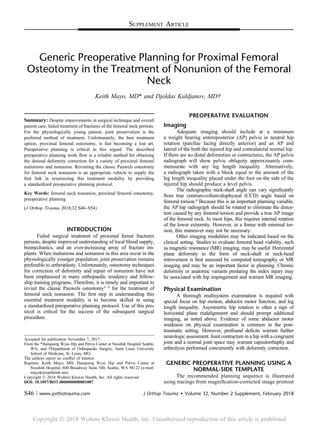
- 1. SUPPLEMENT ARTICLE Generic Preoperative Planning for Proximal Femoral Osteotomy in the Treatment of Nonunion of the Femoral Neck Keith Mayo, MD* and Djoldas Kuldjanov, MD† Summary: Despite improvements in surgical technique and overall patient care, failed treatment of fractures of the femoral neck persists. For the physiologically young patient, joint preservation is the preferred method of treatment. Unfortunately, the best treatment option, proximal femoral osteotomy, is fast becoming a lost art. Preoperative planning is critical in this regard. The described preoperative planning work flow is a reliable method for obtaining the desired deformity correction for a variety of proximal femoral malunions and nonunion. Revisiting the classic Pauwels osteotomy for femoral neck nonunion is an appropriate vehicle to supply the first link in resurrecting this treatment modality by providing a standardized preoperative planning protocol. Key Words: femoral neck nonunion, proximal femoral osteotomy, preoperative planning (J Orthop Trauma 2018;32:S46–S54) INTRODUCTION Failed surgical treatment of proximal femur fractures persists, despite improved understanding of local blood supply, biomechanics, and an ever-increasing array of fracture im- plants. When malunions and nonunion in this area occur in the physiologically younger population, joint preservation remains preferable to arthroplasty. Unfortunately, osteotomy techniques for correction of deformity and repair of nonunion have not been emphasized in many orthopaedic residency and fellow- ship training programs. Therefore, it is timely and important to revisit the classic Pauwels osteotomy1–3 for the treatment of femoral neck nonunion. The first step in understanding this essential treatment modality is to become skilled in using a standardized preoperative planning protocol. Use of this pro- tocol is critical for the success of the subsequent surgical procedure. PREOPERATIVE EVALUATION Imaging Adequate imaging should include at a minimum a weight bearing anteroposterior (AP) pelvis in neutral hip rotation (patellae facing directly anterior) and an AP and lateral of the both the injured hip and contralateral normal hip. If there are no distal deformities or contractures, the AP pelvis radiograph will show pelvic obliquity approximately com- mensurate with any leg length inequality. Alternatively, a radiograph taken with a block equal to the amount of the leg length inequality placed under the foot on the side of the injured hip should produce a level pelvis. The radiographic neck-shaft angle can vary significantly from true centrum-collum-diaphyseal (CCD) angle based on femoral torsion.4 Because this is an important planning variable, the AP hip radiograph should be rotated to eliminate the distor- tion caused by any femoral torsion and provide a true AP image of the femoral neck. In most hips, this requires internal rotation of the lower extremity. However, in a femur with minimal tor- sion, this maneuver may not be necessary. Other imaging modalities may be indicated based on the clinical setting. Studies to evaluate femoral head viability, such as magnetic resonance (MR) imaging, may be useful. Horizontal plane deformity in the form of neck-shaft or neck-head retroversion is best assessed by computed tomography or MR imaging and may be an important factor in planning. Chronic deformity or anatomic variants predating the index injury may be associated with hip impingement and warrant MR imaging. Physical Examination A thorough multisystem examination is required with special focus on hip motion, abductor motor function, and leg length inequality. Asymmetric hip rotation is often a sign of horizontal plane malalignment and should prompt additional imaging, as noted above. Evidence of some abductor motor weakness on physical examination is common in the post- traumatic setting. However, profound deficits warrant further neurologic assessment. Joint contracture in a hip with a congruent joint and a normal joint space may warrant capsulorrhaphy and arthrolysis performed concurrently with deformity correction. GENERIC PREOPERATIVE PLANNING USING A NORMAL-SIDE TEMPLATE The recommended planning sequence is illustrated using tracings from magnification-corrected image printout Accepted for publication November 7, 2017. From the *Hansjoerg Wyss Hip and Pelvis Center at Swedish Hospital Seattle, WA; and †Department of Orthopaedic Surgery, Saint Louis University School of Medicine, St. Louis, MO. The authors report no conflict of interest. Reprints: Keith Mayo, MD, Hansjoerg Wyss Hip and Pelvis Center at Swedish Hospital, 600 Broadway Suite 340, Seattle, WA 98122 (e-mail: mayok@earthlink.net). Copyright © 2018 Wolters Kluwer Health, Inc. All rights reserved. DOI: 10.1097/BOT.0000000000001087 S46 | www.jorthotrauma.com J Orthop Trauma Volume 32, Number 2 Supplement, February 2018 Copyright Ó 201 Wolters Kluwer Health, Inc. Unauthorized reproduction of this article is prohibited.8
- 2. from a picture archive and communication system. This exercise can be replicated with only minor modifications in a completely computerized work flow using virtually any currently available preoperative planning software. A 58-year-old female marathon runner sustained a min- imally displaced right femoral neck stress fracture (Fig. 1A). Eight months later, she remained painful in the groin with weight bearing (Fig. 1B). Computed tomography obtained at that time showed no evidence of fracture union. The lateral radiograph in this case did not show any discernible sagittal or horizontal plane deformities, which correlated with the physical examination. Therefore, the preoperative planning in this case was restricted to the coronal plane and based on the AP imaging. As is often the situation, multiple FIGURE 1. The postoperative AP hip radiograph (A) after the initial sur- gery for the index right femoral neck fracture is shown. The radiograph obtained 8 months later (B) shows implant failure and a displaced fracture. FIGURE 2. The normal-side AP hip radiograph (A) reversed and cor- rected for rotation is used as a tem- plate using a CCD angle of 135 degrees. The injured-side right hip AP radiograph (B) is traced and the altered CCD angle is drawn. J Orthop Trauma Volume 32, Number 2 Supplement, February 2018 Generic Preoperative Planning for Proximal Femoral Osteotomy Copyright © 2018 Wolters Kluwer Health, Inc. All rights reserved. www.jorthotrauma.com | S47 Copyright Ó 201 Wolters Kluwer Health, Inc. Unauthorized reproduction of this article is prohibited.8
- 3. broken retained implants provide an additional surgical challenge. Step 1 The normal-side (left) AP hip radiograph corrected for rotation is reversed and traced for use as a template using a CCD angle 135 degrees (Fig. 2A). The injured-side right hip AP radiograph is traced and the altered CCD angle, as measured at 110 degrees, is drawn (Fig. 2B). The angle subtended by the nonunion and a horizontal ref- erence line is 70 degrees. This angle described by Pauwels has been used as correction guide dating to his original work.1,2 Step 2 Next the tracing of the injured hip is placed over the normal template and aligned based on available landmarks (Fig. 3A). In this case, the lesser trochanter and diaphysis are the primary alignment reference points. When the deformity encompasses the trochanters, this overlay process is some- what subjective, relying predominantly on the contour of the femoral diaphysis and clinical or ancillary radiographic FIGURE 3. The tracing of the injured hip is placed over the normal template and aligned based on available landmarks (A) and a pri- mary transverse osteotomy at the intertrochanteric level (superior aspect of the lesser trochanter) has been selected for preliminary evalu- ation (B). FIGURE 4. Templates of a pure opening wedge osteotomy (A), a pure closing wedge osteotomy (C), and a combination opening/ closing osteotomy (B) are shown. Mayo and Kuldjanov J Orthop Trauma Volume 32, Number 2 Supplement, February 2018 S48 | www.jorthotrauma.com Copyright © 2018 Wolters Kluwer Health, Inc. All rights reserved. Copyright Ó 201 Wolters Kluwer Health, Inc. Unauthorized reproduction of this article is prohibited.8
- 4. FIGURE 5. A pure closing wedge construct was selected for this patient and templated (A). The competed template is then overlaid on an offset high-angled blade plate template (B). FIGURE 6. The seating chisel path is transferred to the original deformity drawing, which is then overlaid on the final construct drawing from Fig. 5B (A). The last step in the plan is a summation drawing with all refer- ence K-wires that will be used at some stage in the case (B). J Orthop Trauma Volume 32, Number 2 Supplement, February 2018 Generic Preoperative Planning for Proximal Femoral Osteotomy Copyright © 2018 Wolters Kluwer Health, Inc. All rights reserved. www.jorthotrauma.com | S49 Copyright Ó 201 Wolters Kluwer Health, Inc. Unauthorized reproduction of this article is prohibited.8
- 5. clues for the assessment of limb length. The goals of this overlay are to determine the frontal plane angular defor- mity, as well as the limb length discrepancy and any hip offset abnormality. In this case, the measured frontal plane deformity is 25 degrees based on the angle formed by the respective neck axes (Fig. 3A), which should match the simple subtraction result of normal CCD—deformity CCD (Figs. 2A, B). Shortening measures nearly 2 cm and fortunately, despite varus collapse, total offset is not diminished. In general, the proximal and distal segments of the malunion/nonunion outline are provisionally selected on the basis of correction versatility and healing time with a goal of minimizing secondary deformity. Here, a primary transverse osteotomy at the intertrochanteric level (superior aspect of the lesser trochanter) is selected for preliminary evaluation (Fig. 3B). This configuration is the easiest to plan and execute and allows rotational correction before any type of closing wedge ostectomy from the distal seg- ment. Bone healing is relatively rapid at this level (6–8 weeks in most cases), and there is modest alteration of the native anatomy. While this initial planning step is the most straightforward, it is important to recognize that there are many configurations possible and multiple plans may need to be generated before a final selection is made. Step 3 The degree of frontal plane correction in the setting of femoral neck nonunion is based on the goal of generating compression across a nonunion plane previ- ously dominated by shear forces.1,2 Initial guidelines called for limiting the nonunion (Pauwels) angle relative to the horizontal to 25 degrees or less. Because most nonunions occur in Pauwels type III fractures, achieving this goal results in a high CCD angle in many patients, and this type of anatomic alteration (coxa valga) has been associated with increased risk for hip and knee arthritis.5,6 However, this 25-degree figure persists in the literature.7,8 Therefore, it is important to be knowledgeable regarding the internal fixation limitations in the Pauwels era. Many of Pauwels osteotomies were stabilized with tension band wires alone. Routine use of the angled blade plate, first widely reported by Marti et al,9 has allowed modification of the correction goals to limit increases in resultant CCD without compro- mising healing of the nonunion. Against this backdrop, the decision was made in this case to perform a frontal plane valgus osteotomy of 30 degrees, which takes into account a small increase beyond the 25 degrees needed to replicate the contralateral CCD angle. The resultant CCD angle on the operated side will be 140 degrees. In the authors’ experience, it is rarely indicated to exceed this degree of valgus. The decision-making regarding an opening wedge osteotomy versus a closing wedge or a combination thereof is based on leg length and bony stability considerations. A pure opening wedge (Fig. 4A) gains the most length but is the least stable because of the limited initial bony contact and potential compromise in tensioning of the plate. Bone grafting will only partially mitigate these shortcomings. Although an opening wedge osteotomy can be a relatively safe technique in children and adolescents, as used for other indications, it is rarely used in adults. A pure closing wedge osteotomy (Fig. 4C) compromises length restoration but provides the most stable construct secondary to bone- on-bone contact area and plate loading. A combined medial opening/lateral closing wedge technique (Fig. 4B) is a scal- able intermediate useful in many patients. Lateral shaft displacement denoted by arrows parallel to the primary osteotomy plane (Figs. 4B, C) represents another variable in correction. In closing wedge valgus osteotomies, it can provide an additional lengthening tool. However, distorting the relationship between the greater trochanter/metaphysis FIGURE 7. Illustration of offset or “mismatch” tensioning of the plate to effect compression at the osteotomy site. Mayo and Kuldjanov J Orthop Trauma Volume 32, Number 2 Supplement, February 2018 S50 | www.jorthotrauma.com Copyright © 2018 Wolters Kluwer Health, Inc. All rights reserved. Copyright Ó 201 Wolters Kluwer Health, Inc. Unauthorized reproduction of this article is prohibited.8
- 6. and the femoral canal can make a subsequent salvage hip arthroplasty difficult and should be undertaken cautiously. Correction of acquired (posttraumatic) varus to near normal alignment should have a positive effect on limb mechanical axis. Therefore, the risk for knee arthritis is likely only in instances of excessive CCD angles, as noted above. Step 4 A pure closing wedge construct (Fig. 5A) was selected for this patient. Stability and bony healing time were believed to be paramount considerations in this relatively older patient. The compromise was accepting the ability to achieve only 50% of the optimum lengthening. Once the final osteotomy FIGURE 8. The final result (A) should match the preoperative plan (B). FIGURE 9. AP (A) and lateral (B) hip radiographs of a femoral fracture treated with a sliding hip screw show lag screw cut out and fixation failure 3 months postoperatively. J Orthop Trauma Volume 32, Number 2 Supplement, February 2018 Generic Preoperative Planning for Proximal Femoral Osteotomy Copyright © 2018 Wolters Kluwer Health, Inc. All rights reserved. www.jorthotrauma.com | S51 Copyright Ó 201 Wolters Kluwer Health, Inc. Unauthorized reproduction of this article is prohibited.8
- 7. configuration template is completed, it is overlaid on an offset high-angled blade plate template (Fig. 5B). The blade angu- lations available are 110, 120 and 130 degrees. The easiest technique and best fit in this case will use a 120 degrees plate. If our planning is correct, insertion of the blade seating chisel orthogonal to diaphyseal axis will result in a 30-degree frontal plane correction as the side plate is applied to the shaft. In the event of sagittal plane deformity (flexion or extension), com- pensatory seating chisel adjustments must be made for the subsequent blade plate placement. These adjustments may create an anterior or posterior gap at the osteotomy interface, which can be managed with a small closing wedge ostectomy from the proximal segment or more simply by filling it will morselized graft from the primary closing wedge. Step 5 Next, the seating chisel path is transferred to the original deformity drawing, which is overlaid on the final FIGURE 10. Summation (A) and final result (B) tempating are shown. FIGURE 11. AP (A) and lateral (B) hip radiographs showing the clinical result at 1 week postoperatively. Mayo and Kuldjanov J Orthop Trauma Volume 32, Number 2 Supplement, February 2018 S52 | www.jorthotrauma.com Copyright © 2018 Wolters Kluwer Health, Inc. All rights reserved. Copyright Ó 201 Wolters Kluwer Health, Inc. Unauthorized reproduction of this article is prohibited.8
- 8. construct drawing from Figure 5B (Fig. 6A). This path should be orthogonal to the long axis as discussed previously. The last step in the plan is a summation drawing with all reference K-wires that will be used at some stage in the case (Fig. 6B). From distal to proximal, these K-wires are orthogonal to the diaphysis, proximal and distal components of the closing wedge, seating chisel reference, and trochanteric tip. Distan- ces from the seating chisel reference to the trochanteric tip and transverse intertrochanteric osteotomy plane are mea- sured. The closing wedge osteotomy reference wires will interfere with seating chisel placement and are placed only after seating chisel insertion has been completed. It may be useful to use these K-wires as “cutting guides” for the sur- geon who is inexperienced in this procedure. Step 6 Plan execution requires familiarity with the blade plate instrumentation and the ability to generate osteotomy site compression (Fig. 7). This offset or “mismatch” tensioning of the plate is used with high-angle blade plates for which an articulated tensioner is poorly suited. The plate is attached distally with a single screw after abutting the lateral osteot- omy surface but leaving a modest (approximately 5–6 mm) gap between the proximal lateral cortex and the side plate. A plate lag screw is then placed proximally in the first or second hole in the plate. As this screw is tightened, the femoral shaft is lateralized and compression is generated progressively from medial to lateral at the osteotomy site. If the bone den- sity is questionable, it is wise to use 2 proximal screws, which are alternately tightened, to minimize the risk of screw pull out. When the plan is well executed, the final result should match the preoperative plan (Figs. 8A, B). CLINICAL CASE A sliding hip screw was used for fixation of a femoral neck fracture in a 42-year-old man. Lag screw cut out and fixation failure was noted at 3 months postoperatively (Figs. 9A, B). The plan in this case was determined to require a 110-degree blade plate inserted off the orthogonal shaft axis to gain fixation in the inferior femoral head below the defect cause by the pre- vious implant (Figs. 10A, B). In this patient, the proximal hip screw channel was to be filled with allograft as well (Fig. 10B). Because of instability noted at the time of surgery, a lag screw was placed above the blade path (Fig. 11A). Despite an initial Pauwels angle of 80 degrees, the planned frontal plane correc- tion was only 30 degrees, resulting in a new CCD angle of 135 degrees (Figs. 10B and 11A, B). Uneventful union occurred of both the femoral nonunion and osteotomy site, further illustrat- ing the point that historically described large corrections are rarely, if ever, needed (Figs. 12A, B). CONCLUSION The above preoperative planning work flow has proven a reliable method for obtaining desired deformity corrections for a variety of proximal femoral malunion and nonunions. It is easily adapted to both old style hard copy radiograph or digital/ picture archive and communication system environments. REFERENCES 1. Pauwels F. Der schenkelhalsbruch ein mechanisches problem: Grundla- gen des Heilungsvorganges Prognose und kausale Therapie. Stuttgart, Germany: Ferdinand Enke Verlag; 1935. 2. Pauwels F. Biomechanics of the Normal and Diseased Hip. Berlin, Ger- many: Springer-Verlag; 1976. 3. Weber BG, Cech O. Pseudarthrosen: Pathophysiologie, Biomechanik, Therapie, Ergebnisse. Bern, Switzerland: Verlag Hans Huber; 1973. FIGURE 12. AP (A) and lateral (B) hip radiographs showing union of both the femoral nonunion and os- teotomy site. J Orthop Trauma Volume 32, Number 2 Supplement, February 2018 Generic Preoperative Planning for Proximal Femoral Osteotomy Copyright © 2018 Wolters Kluwer Health, Inc. All rights reserved. www.jorthotrauma.com | S53 Copyright Ó 201 Wolters Kluwer Health, Inc. Unauthorized reproduction of this article is prohibited.8
- 9. 4. Kay RM, Jaki KA, Skaggs DL. The effect of femoral rotation on projected femoral neck shaft angle. J Pediatr Orthop. 2000;20:736–739. 5. Benlidayi C, Guzel R, Basaran S. Is coxa valga a predictor of knee oste- oarthritis? A cross-sectional study. Surg Radiol Anat. 2014;37:359–366. 6. Pedoia V, Samaan M, Souza R. Study of the interactions between prox- imal femur 3D bone shape, cartilage health and biomechanics in patients with hip osteoarthritis. J Orthop Res. 2017 [epub ahead of print]. 7. Magu NK, Rohilla R, Singh R, et al. Modified Pauwels’ intertrochanter- icosteotomy in neglected femoral neck fracture. Clin Orthop Relat Res. 2009;467:1064–1073. 8. Anglen JO. Intertrochanteric osteotomy for failed internal fixation of fem- oral neck fracture. Clin Orthop Relat Res. 1997;341:175–182. 9. Marti RK, Schuller HM, Raaymakers EL. Intertrochanteric osteotomy for non-union of the femoral neck. J Bone Joint Surg Br. 1989;71:782–787. Mayo and Kuldjanov J Orthop Trauma Volume 32, Number 2 Supplement, February 2018 S54 | www.jorthotrauma.com Copyright © 2018 Wolters Kluwer Health, Inc. All rights reserved. Copyright Ó 201 Wolters Kluwer Health, Inc. Unauthorized reproduction of this article is prohibited.8