1. Page 1 of 5
SCS
®
Spot Welding Guidelines
As prepared by Richard Dunbar of Welding Engineering Associates, Inc., Fischers, IN
Actual weld testing was performed at Unitrol Electronics, Northbrook, IL
This project indicates that SCS processed steel is suitable for the resistance welding process. Findings show that SCS is
superior in weldability to hot-rolled black (HRB) steel, and equivalent to hot-rolled pickled & oiled (HRP&O) steel.
Spot welding SCS processed steel requires regular cleaning of the electrodes, but oxide pick-up when spot welding SCS
is considerably less than HRB or HRP&O. Without cleaning, the SCS surface oxide will accumulate on the electrode
faces causing misshaped weld nuggets. Electrode life when welding SCS is equivalent to life when welding HRP&O.
Basics of Welding Sequence for SCS
The table below lists the parameters included in a resistance welder control, a brief description of each, and a starting
point for settings that should yield good results for spot welding SCS processed material. Base settings were acquired
using .100” thick (12 gauge) of ASME specification SA-414-99 addenda GR-6 pressure vessel quality steel, a low alloy
high strength material. See pages 3 - 5 of this document for guidelines on determining weld quality.
Important note: settings tuned to weld SCS to SCS should also yield good results when welding SCS to HRP&O as
well as when welding HRP&O to HRP&O, so no switching is required.
NOTE: if you are using Soft Touch Software produced by Unitrol Electronics Inc., it requires an
additional hardware item to increase sensitivity for SCS material. Contact Roger Hirsh at Unitrol
Electronics for additional information. (800) 621-4244
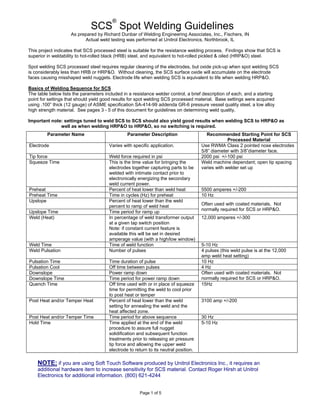
Parameter Name Parameter Description Recommended Starting Point for SCS
Processed Material
Electrode Varies with specific application. Use RWMA Class 2 pointed nose electrodes
5/8” diameter with 3/8”diameter face.
Tip force Weld force required in psi 2000 psi +/-100 psi
Squeeze Time This is the time value for bringing the
electrodes together capturing parts to be
welded with intimate contact prior to
electronically energizing the secondary
weld current power.
Weld machine dependant; open tip spacing
varies with welder set up
Preheat Percent of heat lower than weld heat 5500 amperes +/-200
Preheat Time Time in cycles (Hz) for preheat 10 Hz
Upslope Percent of heat lower than the weld
percent to ramp of weld heat
Upslope Time Time period for ramp up
Often used with coated materials. Not
normally required for SCS or HRP&O.
Weld (Heat) In percentage of weld transformer output
at a given tap switch position
Note: if constant current feature is
available this will be set in desired
amperage value (with a high/low window)
12,000 amperes +/-300
Weld Time Time of weld function 5-10 Hz
Weld Pulsation Number of pulses 4 pulses (this weld pulse is at the 12,000
amp weld heat setting)
Pulsation Time Time duration of pulse 10 Hz
Pulsation Cool Off time between pulses 4 Hz
Downslope Power ramp down
Downslope Time Time period for power ramp down
Often used with coated materials. Not
normally required for SCS or HRP&O.
Quench Time Off time used with or in place of squeeze
time for permitting the weld to cool prior
to post heat or temper
15Hz
Post Heat and/or Temper Heat Percent of heat lower than the weld
setting for annealing the weld and the
heat affected zone.
3100 amp +/-200
Post Heat and/or Temper Time Time period for above sequence 30 Hz
Hold Time Time applied at the end of the weld
procedure to assure full nugget
solidification and subsequent function
treatments prior to releasing air pressure
tip force and allowing the upper weld
electrode to return to its neutral position.
5-10 Hz
2. Page 2 of 5
General Rules for Making Good Spot Welds
as derived by Richard Dunbar from Rules for Spot Welding out of the
Resistance Welder Manufacturers Association’s Resistance Welding Manual
a. Too short squeeze time can result in metal expulsion, overheating electrodes, bad welds, marked work.
b. Too long weld time will shorten electrodes life, cause excessive indentation at surfaces and cause internal cracks
in the weld nugget.
c. A peel destructive test on test strips of the same material and combination is recommended.
d. Too short weld time will result in low weld strength, in proportion with weld heat.
e. Too short hold time can result in surface expulsion, electrodes sticking, and internal cracks in the weld nugget.
f. Weld pressure too low can result in expulsion of metal, electrode sticking, short electrode life, and possible
internal cracks in the weld nugget.
g. Weld pressure too high can result in variable weld strength, excessive weld current requirements, mushrooming
of electrodes, and excessive indentation.
h. With all other settings correct, adjust weld current to meet weld quality standards using recommended starting
points.
i. Electrode contact face too small will result in too small a spot, excessive electrode mushrooming, and excessive
indentation. Too large an electrode contact area will result in too large a weld (assuming current is set
accordingly). Use RWMA charts for electrode manufacturer recommendations.
j. Electrodes misaligned or miss-matched will result in expulsion, and displaced weld nugget and excessive
electrode wear.
k. Insufficient cooling will result in mushrooming and short electrode life. Adequate water cooling of the welding
system is crucial.
The following comparison, as tested by Richard Dunbar of Welding Engineering Associates, shows that SCS
processed material has no more resistance to spot welding than does HRP&O and in fact has considerably less
resistance than HRB.
Electrical Resistivity of Surface Oxides and Contaminants
HRB 80-100 ohms
HRP&O 15-30 ohms
SCS 15-30 ohms
Note: The surface oxides resulting from any surface contaminants (including oil and dirt) are non-conductive and are
detrimental to any welding process. In the case of resistance spot welding it requires additional electrical power to
break through these surface contaminants and expel the refuse so as to prevent entrapment within the weld metal
nugget.
Properly fused weld metal from the two members being joined must be free of oxides formed from surface
contaminants during welding for sound weld results.
Pages 3 - 5 are excerpts from the Specification for Automotive Weld Quality - Resistance
Spot Welding section of the American Welding Society Standard for more information on
how to determine weld quality.
3. Page 3 of 5
This page is an excerpt from the Specification for Automotive Weld Quality - Resistance Spot Welding
section of the American Welding Society Standard.
4. Page 4 of 5
This page is an excerpt from the Specification for Automotive Weld Quality - Resistance Spot Welding
section of the American Welding Society Standard.
5. Page 5 of 5
This page is an excerpt from the Specification for Automotive Weld Quality - Resistance Spot Welding
section of the American Welding Society Standard.