
Recommended
Recommended
More Related Content
Similar to INTRODUCTION TO AERO WEAPONS.pptx
Similar to INTRODUCTION TO AERO WEAPONS.pptx (20)
Recently uploaded
Recently uploaded (20)
INTRODUCTION TO AERO WEAPONS.pptx
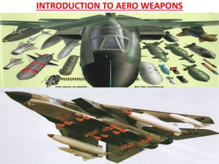
- 1. INTRODUCTION TO AERO WEAPONS
- 2. INTRODUCTION One of the key differences between civilian and military aircraft is that many military aircraft have the ability to carry and release weapons. From the earliest days of aviation where the pilot would drop simple bombs by hand, engineers have striven to develop the capability to accurately deliver weapons against targets reliably and safely. Today, for a successful target engagement, it is essential for the aircraft and weapon to be integrated such that the full capabilities of the weapon can be exploited. The release of a weapon whether it is a forward fired missile or a downward ejected store such as a fuel tank, from either an externally mounted pylon or from an internal bay, creates issues such as the ability to achieve safe separation and the ability of the aircraft structure to withstand the imparted loads. The complexity of weapons integration is increased when the requirements for priming and aiming are considered. The integration of weapons onto aircraft therefore requires a multi-disciplinary set of capabilities within the integration organisation. The generic term for any mission payload carried on an external pylon or an internal bay on a non-permanent basis is a ‘store’. The family of stores includes weapons, fuel tanks, countermeasure pods and so on. Whilst many of the stores would only be released from the aircraft under emergency conditions (e.g. in the event of an engine failure during take-off),weapons are designed to be released as a matter of course
- 3. The Systems Integration Process As with any system design, a structured, top-down approach is essential. However, for weapons integration, the higher level requirements will also include aeromechanical aspects such as the desired release envelope, carriage life, the number of weapons that can be carried, influences of other weapon and store types to be carried on the same sortie, and so on. This segmentation process may use software-based requirements management tools as these will, in due course, assist in the validation and verification of the system implementation against the requirements. This partitioning exercise depends on the actual aircraft system architecture and will therefore differ between aircraft, with the requirements being partitioned to individual aircraft subsystems, which could be implemented in both hardware and software. Each requirement placed on the aircraft’s subsystems will need to be proven for correct implementation, and the subsystems will then be progressively built up into an overall integrated system that provides the required military capability. This will include the testing of the system and its components in a Systems Integration Laboratory (SIL). Employing either weapon simulators or inert weapons with operational electronics, integration testing will test that all the aircraft subsystems are working together to control the weapon. Any problems which are
- 4. Stores Management System Design The first electrical systems to control the release of stores were based on relays that when energised would switch the current to the bomb rack, causing it to open. The relays were operated by the Bomb Aimer pressing the release button, thereby routing a current to the relay coils. From a safety and certification viewpoint, it is essential that an aircraft only releases a store when intended. This appears to be an obvious requirement, but it is the primary driver in the design of the armament system of an aircraft. In a modern military aircraft, the simplicity of the first electrical systems has been replaced by a subsystem in its own right which is generally referred to as the Stores Management System (SMS). The SMS manages the weapon load-out and controls the safe arming, release, jettison and operation of any store loaded on the aircraft, including the generation of the high-integrity data messages required by modern smart weapons to ensure their safe operation. This increased level of functionality and the need to ensure that weapons are only released or jettisoned when required are the primary drivers in SMS design, adding complexity to the hardware implementation and introducing the need for embedded safety critical software
- 5. The Global Positioning System & Weapon Initialisation and Targeting The Global Positioning System The accuracy to which weapons can be delivered on target is a key requirement of most new weapon programmes. Since the first Gulf War in 1991, there has been an increased use of navigation technology such as the United States’ Global Positioning System (GPS) to assist in the terminal guidance of weapons. This increased use of GPS receivers in guided weapons has enabled the continued potency of legacy aircraft. The integration of such so-called smart weapons brings with it special problems for the aircraft systems integrator. Weapon Initialisation and Targeting Different weapons demand different methods of targeting. Targeting a weapon, be it an Air- to-Ground weapon or an Air-to-Air missile, can be very complex and place great demands on the performance of the aircraft systems. For the accurate targeting of a smart weapon, it is essential that the aircraft and weapon axis reference systems are initialised to provide a common reference, thereby removing position and velocity errors. There are different ways in which weapons are targeted covering the accurate delivery of ballistic bombs, the flexibility of targeting for smart weapons and the sensor types and target prosecution strategies of Air-to- Air missiles.
- 6. Types of Weapon A key differentiator between a weapon and other types of stores is that weapons are designed to be released as a matter of course in order to prosecute a successful mission. To enable the aircraft systems integration problem space to be explored, it is first necessary to have a basic understanding of weapons and their subsystems. Range of weapon types will include simple ballistic bombs, Air-to-Air missiles and modern ‘smart’ weapons and will identify the primary requirements of a weapon. Have to identify how these requirements generate the need for individual weapon subsystems and the demands these place on the launch aircraft. Multi-weapon carriage systems will also be considered as the means to increase weapon load-out, albeit by increasing the complexity of the systems integration activities. Their requirements will enable the aircraft systems integration problem space and the differences in the integration of each weapon type to be explored . However, before considering weapon requirements, it is first necessary to understand the typical types of target that the weapon will have to defeat. It is those basic requirements which drive the design of the weapon including the need for the primary weapon subsystems.
- 7. Targets The primary aim of an air-launched weapon is to cause an effect on its target is to destroy the target by the energy released during the weapon’s impact. In a military conflict, there are many types of potential targets such as troops, buildings, vehicles, other aircraft, ships and airfields. The successful destruction of these targets requires the employment of different warheads and delivery methods. For example, in the past, weapons such as cluster bombs were employed against troops. Whilst effective against people, a cluster bomb is all but useless against a hardened building, where a bomb with a level of penetration capability and a blast warhead would be more effective. Engagement of airborne targets also requires a delivery mechanism such as a homing missile for engagement. An examination of the different types of weapon which can be found in the inventories of the world’s air forces will show that ballistic bombs, bombs with added control mechanisms that improve accuracy and powered weapons having a greater stand-off range (including Air to- Air and Air-to- Ground missiles) exist, each to be used against different targets. It is important to remember that weapons only exist to satisfy a military need. It is this which ultimately dictates the design and configuration of any weapon, and hence its integration complexity.
- 8. Weapon Requirements For any weapon, there are three basic requirements. - Lethality against its intended target, - The accuracy (precision) with which it can engage the target and - The stand-off range from which it can be launched against the target. From the above three basic requirements, All the detailed design requirements of a weapon can be derived, detailed requirements which in turn drive the choice of weapon subsystems required to ensure a successful target engagement.
- 9. LETHALITY Warheads • The achievable lethality of a weapon against a target will depend on the target type and the warhead used. Table in next slide identifies the common types of warhead that could be used to defeat • It would be possible to deploy a warhead against a target for which it was not designed to defeat. • Whilst there may still be some effect on the target, this is unlikely to be optimised and raises the risk of collateral damage. • For greatest effect on the target, the warhead must be detonated at the right instant. For example, a shaped charge is most effective when it is detonated at a distance above the armour plate at which it is aimed. • This is because the molten metal jet takes a finite time to build. If the warhead is detonated too early, the jet will have started to collapse before it comes into contact with the armour. • If the warhead is detonated too late, then the jet will not have sufficient time to build. Both these cases could significantly reduce the efficiency of the weapon.
- 10. LETHALITY
- 11. LETHALITY Fuzes Many different types of fuzing systems exist with probably the simplest being an impact fuze. Here, the rapid deceleration of the weapon is detected and a small pyrotechnic charge is initiated which itself initiates the main explosive charge of the warhead. For penetrating weapons the fuze could be enhanced to incorporate a circuit that delays initiation. This enables the weapon to penetrate the target before detonating, thereby maximising damage. A third type of fuze is the crush fuze which is usually mounted on a frangible circuit board located at the front of some weapons. When impact is sensed by the initial impact breaking an electrical loop embedded in the card, the pyrotechnic chain is initiated. As noted earlier, the effect of some types of warhead is maximised if they are initiated before impact. For this, some form of proximity sensor would be employed which uses radio frequency pulses or a pulsed laser to continuously measure the distance between the sensor and its target. For weapons requiring an air-burst, it is not uncommon for a simple radar altimeter to be employed as the sensing input to the fuze initiation circuits. As different targets require different fuze operation and performance, modern weapon fuzes often have their functions programmable via the interface with the aircraft. Typical parameters that could be programmed are identified in Table to follow.
- 12. LETHALITY
- 13. Precision When specifying a weapon, the accuracy with which it can engage its target is important. Ballistic, unguided bombs are notoriously inaccurate with miss distances of the order of tens of metres . By comparison, modern guided weapons can achieve precision engagements in the single metre or less range. A precision-guided weapon therefore enables warhead size to be reduced such that more of the explosive yield of the warhead is used to defeat the target, rather than it being wasted or being the cause of collateral damage. The need for precision therefore drives the need for a control system to manoeuvre the weapon. This is often coupled with a sensor that can detect the target and an autopilot to determine the projected miss distance and make control surface corrections to steer the weapon on to its target
- 14. Precision Sensors Guided weapons employ many different types of sensors including those that can detect heat or reflected laser energy, imaging sensors (both video and Imaging infra-red (IIR)), radar and in-built navigation such as inertial systems (now usually supplemented by a GPS receiver). Although some early weapons used video sensors, by far, the most successful of early guided weapons were those that had a sensor that could detect laser energy reflected from the target. The laser energy is generated, for example, by a portable system such as would be used by a forward air controller, or by a designator pod carried either by the launch aircraft or by a co- operating aircraft. The use of a laser designator pod (which itself, often has the laser function integrated as a part of a more complex electro-optical targeting pod) provides the aircraft with an excellent capability to detect and attack static targets. However, one major shortfall is that the laser has to be illuminating the target constantly during the engagement, and this is not always possible due to, for example, smoke or weather. For this reason, weapons that employ an inertial system coupled with a GPS receiver have been developed. This enables targets with a known location to be engaged when purely visual conditions are unfavourable. When conditions permit, the use of a laser to supplement the inertial/GPS improves end- game precision. Air-to-Air missiles generally employ one of two types of sensors, these being infra-red (IR) and radar (although some missiles employ both sensor types).
- 15. Precision Early Air-to-Air missiles employed a single-element IR sensor to detect the heat emitted from an enemy fighter’s engines. This relatively simple technology would detect any source of heat including the sun or heat reflected from the launch aircraft’s fuselage, thereby causing the missile to lock on to a false target. Although early seekers were improved to counter false targets, modern IR sensors now use IIR focal plane arrays. This enables the missile control algorithms to discriminate between a real aircraft target and false or spoof targets (e.g. IR countermeasure flares). For longer range engagements, an IR sensor does not provide adequate performance. Radar sensors have a significantly greater range and therefore afford the ability for a fighter aircraft to increase its stand-off distance from its target. However, with the increased use of jamming as a defensive mechanism, radar sensors employ counter-countermeasures such as providing a ‘home on jam’ capability where the sensor acts in a passive mode to identify the relative bearing of the jamming signal, enabling the missile’s guidance electronics to manoeuvre and home in on the source of the jamming signal. A variation of ‘home on jam’ is to use a radio frequency receiver to detect the signals from an air defence radar, enabling the weapon to home in on to the transmitter.
- 16. Precision Control Systems Once a weapon knows where its target is, it needs to be able to steer itself so that it achieves a successful engagement. Guided weapons therefore need to have aerodynamic surfaces driven by actuators, which themselves are controlled by a system which is capable of translating information from the sensor into guidance commands. Some weapons have a simple system which makes multiple, low-granularity changes to the weapon’s flight path. Other weapons such as cruise missiles would normally employ a complex system of an autopilot that can fly a route, supplemented by a radar altimeter and possibly a terrain data base to enable covert approaches to the target.
- 17. Stand-Off Range The final requirement for a guided weapon relates to the range at which it can be launched against its intended target. Ballistic bombs depend solely on the kinetic and potential energy at launch. For low-level bombing, this severely restricts the range the weapon can travel before it impacts the ground. For greater stand-off range, bombing from higher altitudes can be used but then the flight path of the unguided ballistic bomb becomes less predictable as aerodynamic forces and weather influences such as air density, wind speed and direction start to have an effect. However, greater stand-off range enables the launch aircraft to remain out of range of air defences, thereby improving survivability. Weapon stand-off range can be extended by a number of means, the simplest being to add aerodynamic surfaces (e.g. the addition of a deployable wing kit such as that employed by the United States’ Small Diameter Bomb II (SDB II – see Figure 1.1) that provide lift, thereby reducing the decent rate due to gravity).
- 18. Stand-Off Range For a greater stand-off range, aerodynamic lifting surfaces must be supplemented by a power source to provide thrust. Rocket motors can give high acceleration and boost the weapon to very high speeds (>> Mach 1), albeit with a relatively short burn time. This is very useful for weapons such as Air-to-Air missiles where time to complete the engagement is critical. For even greater stand-off ranges, turbojets (e.g. in a cruise missile) or a ramjets (for a long range, high-speed engagement) are also employed.
- 19. Typical Weapon Configurations From the brief overview of the requirements that drive weapon design, it is clear that a typical guided weapon contains a number of individual subsystems that all contribute to a successful target engagement. These subsystems require a power source, and in missiles with a relatively short time of flight, thermal batteries are typically employed (a thermal battery is a chemical device initiated by a pyrotechnic squib; the battery electrolyte, which is normally a solid and relatively inert, melts and the battery becomes active). For longer range weapons such as cruise missiles, internal power may be provided by a generator turned by a power take-off shaft from the turbojet engine. Weapons may also contain a post-launch data link which can be used to receive target position updates. The following figures show three typical weapon configurations, covering a Precision-Guided Bomb (Figure 1.2), an Air-to-Air missile (Figure 1.3) and A cruise missile (Figure 1.4).
- 22. Implications for the Launch Aircraft The primary roles of the launch aircraft from the weapon’s viewpoint are to transport it to a point where it can be released against its target, to ensure that it is operational prior to launch, to provide the necessary priming to ensure that it has the best chance of engaging the target, and to ensure that it separates cleanly from the aircraft when launched. The weapon cannot perform its task unless it has been correctly initialised by the aircraft. For example, the aircraft will have to provide power to the weapon pre-launch for the purposes of target programming, testing (by built-in test functionality within the weapon) and aligning the weapon’s navigation subsystem and sensors. When powered, the weapon may also provide data on request by the aircraft which includes its type and its operational status and data for reading back stored target data. From a systems integration viewpoint, it is the electrical connector that provides the primary interface. It is through this interface that the aircraft ensures that the weapon is operational prior to launch and provides the necessary priming to ensure that the weapon has the required precision for a successful target engagement. The weapon will have a number of other interfaces with the launch aircraft which include physical interfaces such as the mechanical attachments, fuzing lanyards and the electrical connector. However, other interfaces presented by the environment (e.g. aerodynamic forces, physical forces such as vibration and the electromagnetic environment) also exist
- 23. Implications for the Launch Aircraft
- 24. Carriage Systems Mechanical Attachments The advent of smart weapons has driven the need to have smart multi- weapon carriage systems which are capable of controlling modern guided weapons. The basic carriage systems employed and how these have been adopted and, in some cases, coupled with complex electronics to realise a smart multi-weapon carrier are as under. The deployment of air-launched weapons can be achieved in two ways: Downward ejection Forward firing. (for weapons with a rocket motor) Downward Ejection NATO aircraft and downward ejected stores generally use common ‘hook and eye’ mechanical attachments defined by the NATO Standardisation Agreement STANAG 3726. The hook mechanism is part of a pneumatic release unit or bomb rack operated either by the initiation of a pyrotechnic cartridge (the product of which is a high pressure hot gas) or by the release of compressed (cold) gas. Figure 1.5 shows a typical bomb rack.
- 25. Carriage Systems
- 26. Carriage Systems In older systems or systems that are used on aircraft with a relatively low speed, bomb racks may be operated by energising a solenoid that opens the hooks, allowing the weapon to fall away under the effect of gravity In pneumatic systems, in addition to opening the hooks, the gas is also used to operate rams that push the weapon away from the aircraft to aid aerodynamic separation. After the weapon has been mechanically attached to the aircraft (by closing the hooks to grab the eyes fitted to the weapon (bale lugs)), the fuzing attachments are made. These usually consist of mechanical lanyards which remove locking pins from the fuzing mechanism during the bomb release sequence. However, modern programmable fuzes may contain a thermal battery that needs to be activated at the time of release. In this case, a fuzing power supply is switched through to the fuze by the aircraft on release. Other aspects of the physical interfacing of weapons such as connector locations in relation to the mechanical attachment points are defined by MIL-STD-8591. Some Air-to-Air missiles can also be downward ejected. However, for an eject-launched missile, there are currently no standardised mechanical interfaces, and it is left to the WDO to devise the optimum mechanical interfaces.
- 27. Carriage Systems Forward Firing • Air-to-Air missiles and some Air-to-Ground weapons can be launched by igniting the rocket motor and firing the weapon along a rail. • For a rail-launched missile, the mechanical attachments of the launcher are defined by STANAG 3842AA. • However, a shortfall of the standard is that there are few details of the mechanical attachments which the weapon must use to attach to the launcher rail. • The WDO is therefore required to design missile hangers which interface correctly with the defined rails while sustaining the loads for the carriage and operation of the weapon. • The rail is usually a component in a launcher which itself may include • electronics to convert power and signals from the launch aircraft to the power supplies and signals required by the missile. • A missile launcher could therefore be a typical example of single station smart weapon carriage system.
- 28. Carriage Systems Multi-weapon Carriage Systems The earliest multi-weapon carriage systems were used to increase the carriage capability (weapon load-out) of ballistic bombs. These types of carriers provided an extension to the main aircraft carriage system, duplicating the bomb rack and the fuzing connections for multiple bombs. The advent of smart weapons has led to electronics being included in the carrier to convert the interface with a single aircraft electrical connector to multiple interfaces, one for each weapon. Whilst a smart multi-weapon carriage system can increase the overall weapon load-out, this has implications for the aircraft systems integration activity. The aircraft now communicates with the carrier and not necessarily directly with each individual weapon on the carrier. The aircraft will therefore need to know exactly what is loaded on the carrier and at which station so that, for example, the correct navigation system offsets can be applied and target and fuzing data can be passed to the right weapon. Such a configuration will also increase the system data transmission delays, which could mean that the data received by the weapon is stale. In turn, this could have implications for the accuracy of the weapon when launched against a target.