3. numerous technical disciplines and processes necessary to
develop, technically husband, and ultimately bring to fruition
a large-scale highly complex system of systems article of war.
The origin of these papers came about in response to the
ever-increasing development cost and technical complexity
of major weapon systems and the increased role of systems
integration in achieving a successful outcome. It is through
these papers, and the professional dialogue that ensues, that a
historical perspective of the government’s technical role in
these national endeavors can be better understood and future
roles and responsibilities of all technical participants be better
aligned for success. For there is nothing more complex, more
demanding of engineering mastery, more dominating the
world over, and yet more sensitive to catastrophic system
failure than the naval warship at sea defending our nation; yet
that is what a warship is built to do.
2. BACKGROUND
This section provides a brief description of the major concepts
and systems being addressed within this technical paper.
These concepts and systems include: BMDS, Federalism,
SoS and Family of Systems (FoS), Graph Theory, Department
of Defense Architecture Framework (DoDAF), and ABM. In
addition, the concept of mission thread will be introduced in
each section to tie the individual functional pieces of the
system together in terms of an overarching Concept of Opera-
tions (CONOPS) [ASN/RDA, 2006]. A CONOPS is a docu-
ment describing the characteristics of a proposed SoS from
the viewpoint of an individual who will use it. It is used to
communicate the quantitative and qualitative SoS charac-
teristics to all stakeholders. It generally evolves from a con-
ceptual idea and describes how a capability may be employed
to achieve a desired objective against an enemy threat or a
particular end state with a specific scenario or mission thread.
In terms of the DoDAF, the Operational Views (OVs) repre-
sent the CONOPS through graphical illustrations which show
the multiple systems and the interactions among these sys-
tems in forming an SoS and warfighting capability.
2.1. BMDS Overview
Today’s Theater Ballistic Missile Defense System can be
viewed as an SoS that is a unique and time-dependent con-
struct based on the current threat, available assets, geographic
constraints, and the CONOPS defined by the responsible
Combatant Command (COCOM). A recent example of a
theater BMDS would be the joint response demonstrated by
the United States and Japan in setting up defensive systems
to prepare for the recent North Korean launch of the Taepo-
dong-2 missile [Yamaguchi, 2009]. The BMDS created for
the North Korean launch appears to consist of U.S. Aegis
sea-based missile defense capabilities [Kim, 2009], the two
Japanese destroyers with U.S. Aegis BMD capability, Japa-
nese and U.S. land-based Patriot Advanced Capability-Phase
3 (PAC-3) batteries, the Japanese network of FPS-5 and
upgraded FPS-3 radars, and the U.S. FBX-T (AN/TPY-2)
forward-based radar in Shariki [MOD Japan, 2009]. This
theater BMDS is truly a response to an immediate require-
ment, and appears as a loosely coupled federation of inde-
pendently functional systems. This BMDS SoS appears to
have multinational and multiservice C2 under both U.S. Pa-
cific Command (USPACOM) and U.S. Strategic Command
(USSTRATCOM). This relevant, notional example of a thea-
ter BMDS will be used as aconstructto studySoS engineering
and integration.
A common goal of the theater BMDS is the use of the
“best” sensor(s) to provide track data to the fire control loop
of the “best” weapon system for any given threat intercepts
[MDA, 2009]. Here, the term “best” implies adequate enough
to meet stringent engagement timelines. Often, the sensor (or
weapon) with the superior performance characteristics may
be unable to meet time requirements due to deficiencies in
interoperability, communications, positional placement, or
doctrine. Superior components may be suboptimal in SoS
context due to interstitial related issues. Key attributes of a
theater BMDS fire control loop include functionally net-
worked communications, distributed C2 and Battle Manage-
ment (BM), tactical nature of the theater assets available, and
integrated SoS performance driven by constituent system
interoperability. Interoperability can be affected by the nature
of available communications, typically LINK16; the na-
ture/maturity of the constituent systems and interfaces be-
tween the constituent systems; the nature/maturity of the SoS
architecture or the dynamic nature of the diverse and distrib-
uted C2/BM infrastructure. Developing, testing, and fielding
effective, integrated, and interoperable fire control across a
theater wide fire control loop would be challenging both
technically and managerially. According to reports from the
Government Accountability Office (GAO), the ability of the
U.S. Department of Defense (DoD) acquisition community
to deliver this type of system in terms of cost, schedule, and
performance is problematic [GAO, 2009]. With today’s need
for joint federated systems to counter the growing air and
missile threat, we must begin to consider SoS requirements
in the development of individual system elements and com-
ponents. Defining and assessing the viability of integration
requirements will require tools for requirements analysis and
system-of-system design synthesis. A central theme of the
GAO report is lack of effectiveness in integrating complex
components and systems together and the inability to effec-
tively demonstrate the integrated capability against require-
ments.
As the U.S. MDA continues to pursue the capability-based
acquisition strategy, and theater BMDS capabilities are de-
ployed, the analytical challenge is to understand how to
achieve BMDS performance consistent with initial perform-
ance goals and predictions. The U.S. DoD has constructed a
vision for the configuration of the BMDS in 2013 as shown
in Figure 1. This is a sea-, land-, and space-based multiservice
capability. Key characteristics of the theater portion of the
BMDS are the layered lower and upper tier capability of
PAC-3, Terminal High-Altitude Area Defense (THAAD), and
Aegis systems with networked sensors, C2, and BM.
Figure 2 illustrates the Japanese Ballistic Missile Defense
Architecture. The Japanese BMDS consists of a layered PAC-
3 and sea-based Aegis capability with a forward-based TPY-2
radar developed in collaboration with the U.S. DoD. The
Japanese Minister of Defense has directed a distributed radar
A SYSTEM OF SYSTEMS FRAMEWORK BALLISTIC MISSILE DEFENSE 3
Systems Engineering DOI 10.1002/sys
4. Figure 1. U.S. BMDS system configuration for 2013.
Figure 2. Japanese BMD architecture.
4 GARRETT ET AL.
Systems Engineering DOI 10.1002/sys
5. network consisting of five FPS-5 radars and seven upgraded
FPS-3 radars be completed by 2011.
Assuming a CONOP associated with a North Korean
ballistic missile threat, a joint U.S./Japan theater BMDS
appears to have significant capabilities inherent to the multi-
ple, distributed constituent systems. What is less obvious is
how the overall SoS will operate as an integrated coherent
whole. In order to emphasize the effective, interoperable
functionality of a specific BMDS architecture, a mission
thread needs to be examined by executing the detailed phases
of the kill chain for specific warfighting scenarios. There are
two specific areas of interest: (1) how the SoS networked
radar and satellite sensors will support an integrated fire
control circuit, and (2) how well the distributed C2 and BM
will help close the fire control circuit to complete the engage-
ment. For this SoS, the Measure of Effectiveness (MoE)
suggested by the authors is The Navy’s Probability of Raid
Annihilation, (PRA). PRA is an important SoS metric that does
not reflect the historic single system objectives of single shot
probability of kill. The new goal is no longer component
optimization, but rather aggregated SoS optimization while
recognizing that the component must also operate in its or-
ganic system at a level meeting all system requirements. The
challenge is to define the functional dependencies across the
SoS and the functional form for an optimized PRA that inte-
grates the fire control loop over the sensor network and upper
and lower tier capability.
2.2. Federalism Approach
Considerable research has been performed involving the de-
velopment of a framework and associated processes for the
systems engineering and management functions supporting
the acquisition of large, complex federated systems. An im-
portant aspect of this research addressed the Principles of
Federation [Handy, 1992] and their application to today’s
complex environment. The key challenges associated with
acquiring a typical complex system include:
• The need to manage interfaces among component sys-
tems that are generally individually acquired and inte-
grated
• The distributed management environment (systems en-
gineering and program management)
• The challenge associated with adaptive and emergent
behavior of the composite systems.
The concept of federalism is particularly appropriate since
it offers a well-recognized way to deal with the systems
engineering management paradoxes of power and control
such that the desired ecological balance is obtained. Gener-
ally, this is accomplished by:
• Making things big by keeping them small
• Encouraging autonomy but within the appropriate
bounds of process and architecture standards
• Combining variety and shared purpose, individuality,
and partnerships at national and global levels.
The concept of federalism is based on five principles set
forth by Handy [1992] that must be adopted, “inside-out” or
“bottoms-up.” These principles are:
1. Subsidiarity (the most important principle)—This prin-
ciple asserts that power belongs to the lowest possible
point within the SoS engineering team.
2. Interdependence (Pluralism)—This principle deals
with the closeness of the autonomous development
units or teams of an SoS development federation due to
the fact that they need one another as much as they need
management leadership and leadership authority. This
interdependence, or pluralism, is key to federalism as
it distributes power. Interdependence avoids the risks
of autocracy and overcontrol of the typical centralized
program management bureaucracy; however, the SoS
program management still serves as the focal point for
action.
3. Uniform and Standardized Way of Doing Business—
This principle is critical from the perspective of creat-
ing an effective and efficient work environment based
on unity of effort. To gain interdependence, an agree-
ment must be made on basic rules of conduct, common
traditions of communicating, and common units of
measurement of progress and quality.
4. Separation of Powers—This principle maintains that
management, monitoring, and governance aspects of
SoS engineering programs and projects be viewed as
separate functions to be accomplished by separate bod-
ies. When these three functions are combined into one
body, short-term needs generally drive out long-term
considerations which could result in path dependency
issues over the lifecycle of the engineering program.
5. Dual Citizenship—This principle contends that every
individual is a “citizen” in two communities: (1) the
local development group/professional group/union and
(2) the overall SoS program at large. Local citizenship
seldom needs much support. The SoS program draws
its strength from the strong leadership of the local
groups. It is federated “citizenship” that requires em-
phasis if the benefits of subsidiarity and interdepend-
ence are to be acquired by sponsors and customers of
an SoS engineering program.
This federation approach has become a highly considered
business model in today’s military structure versus the tradi-
tional top-down approach. The current drive towards adistrib-
uted operations framework places a new focus on the
federalism principles discussed above when you consider the
key performance parameters of speed and agility. From a
mission thread perspective, these principles are key enablers
when considering the development of effective and efficient
warfighting capabilities that involve the rapid transfer of
time-sensitive information across a complex environment.
The movement of this information is a necessary element
towards creating the “unity of effort” across a mission area
that depends on the integration and interoperability of many
systems. A breakdown in any part of this SoS could prove to
be detrimental in the success of a mission, and therefore the
defense of our nation in response to national security issues.
A SYSTEM OF SYSTEMS FRAMEWORK BALLISTIC MISSILE DEFENSE 5
Systems Engineering DOI 10.1002/sys
6. 2.3. System of Systems (SoS) and Family of
Systems (FoS) Concepts
It can be argued that there is no universally accepted definition
of SoS [Sage and Cuppan, 2001]. Since SoS is in its early
stages of development, it is expected that this would be the
case. There are numerous definitions for SoS; however, Sage
and Cuppan offer that the characteristics of an SoS include
operational and managerial independence, geographic distri-
bution, emergent behavior, and evolutionary development.
In addition, the DoD Acquisition Guidebook [DoD, 2004]
makes the following differentiation regarding SoS versus
FoS: An FoS is not considered to be a system per se. An FoS
does not create capability beyond the additive sum of the
individual capabilities of its member systems. An FoS is
basically a grouping of systems having some common char-
acteristic(s). For example, each system in an FoS may belong
to a domain or product lines (e.g., a family of missiles or
aircraft). An FoS lacks the synergy of an SoS. The FoS does
not acquire qualitatively new properties as a result of the
grouping. In fact, the member systems may not be connected
into a whole.
Additional comparisons between SoS and FoS are offered
in the Joint Chief of Staff Instruction 3170.01E, Joint Capa-
bilities Integration and Development System (JCIDS)
[JCIDS, 2005]. The general distinction is that SoS are inter-
dependent to provide capability and FoS are independent:
• System of Systems—a set or arrangement of interde-
pendent systems that are related or connected to provide
a given capability. The loss of any part of the system
will significantly degrade the performance or capabili-
ties of the whole. The development of an SoS solution
will involve trade space between the systems as well as
within an individual system performance [JCIDS,
2005].
• Family of Systems—a set of systems that provide simi-
lar capabilities through different approaches to achieve
similar or complementary effects [JCIDS, 2005].
Systems engineering is a broad topic that includes hard-
ware, software, and human systems. The federalism approach
plays a critical role in the development of an SoS as the
development requires integrating systems across communi-
ties of contractors and sometimes across multiple customer
bases. In general, the development of these systems is man-
aged by more horizontally organized program management
structures, such as the Integrated Process and Product Team
(IPPT), which resonates with conflict due to business, politi-
cal, and other potentially competing interests [Sage and
Rouse, 2009].
For a single system within an operational environment, the
mission objectives are established based on a structured re-
quirements or capability development process along with
defined CONOPS and priorities for development. There is a
strong emphasis on maintaining a specific, well-defined op-
erational focus and deferring changes until completion of an
increment of delivery. Systems engineering inherits these
qualities in an individual system development. On the other
hand, SoS systems engineering is conducted to create opera-
tional capability beyond that which the systems can provide
independently. This may make new demands on the systems
for functionality or information sharing which had not been
considered in their individual designs. In some cases, these
new demands may not be commensurate with the original
objectives of the individual systems.
2.4. Department of Defense Architecture
Framework (DoDAF)
The current DoDAF guidelines, Version 2.0, were approved
on May 28, 2009. These guidelines serve as the overarching,
comprehensive framework and conceptual model enabling
the development of architectures to facilitate the ability of
DoD managers at all levels to make key decisions more
effectively through organized information sharing across the
DoD, Joint Capability Areas (JCAs) [SecDef, 2005], Mission,
Component, and Program boundaries. The DoDAF serves as
one of the principal pillars supporting the DoD Chief Infor-
mation Officer (CIO) in his responsibilities for development
and maintenance of architectures required under U.S. Law
(Clinger-Cohen Act). This version of the framework provides
extensive guidance on the development of architectures sup-
porting the adoption and execution of Net-centric services
within the Department.
The DoDAF architecture products and executable models
define a common approach when pursuing description devel-
opment, presentation, and integration processes for both daily
operations and business operations. The architecture products
define the essential architecture views consisting of opera-
tional, system, and technical views that express the Net-cen-
tric capabilities for interoperability. The resulting executable
model provides a means for theprogrammanager and systems
engineer to work with the stakeholder in translating the archi-
tecture views into verifiable requirements. The development
of the system architectureand corresponding executablemod-
els provide a way to capture the definition of the system
requirements and functional and physical architectures that
define the functional, allocated, and product baselines. The
output of this process is the physical design that results in
design definition documentation such as specifications, allo-
cated and product baselines, and Work Breakdown Structures.
Physical architectures with corresponding executable models
and the resulting design should be sufficiently detailed to
allow for: (1) confirmation of upward and downward trace-
ability of requirements across the functional, allocated, and
product baselines and (2) confirmation of interoperability and
open system performance requirements, and sufficient prod-
uct and process definition to support implementation, verifi-
cation, and validation of the design.
The architecture artifacts need to be refined and reused in
multiple applications across a mission thread to support effec-
tive integration and interoperability across product lines and
evolutionary development approaches. An architecture enter-
prise model depicts the enterprise; its constituent systems,
including the systems to be developed or modified; and enter-
prise actors (entities external to the enterprise). The as-is
architecture products are analyzed using causal analysis tech-
niques to determine its limitations, and used as a basis for
deriving the mission requirements and to-be architecture
6 GARRETT ET AL.
Systems Engineering DOI 10.1002/sys
7. products. The mission requirements are specified in terms of
the mission/enterprise objectives, measures of effectiveness,
and top-level use cases. The use cases and scenarios capture
the enterprise functionality.
Overall, the flow of the Architecture Based Systems Engi-
neering (ABSE) processes is iterative within any one phase
of the acquisition process and is recursive at lower and lower
levels of the system structure [Sage and Rouse, 2009]. The
models within this systems engineering process are applied
to allow an orderly progression from one level of development
to the next more detailed level through the use of functional,
allocated, and product baselines under proper configuration
management. The processes are used for the development of
system, subsystems, and system components as well as for the
supporting or enabling systems used for the testing, produc-
tion, operation, training, support, and disposal of that system.
System architectures provide a means to establish an unprece-
dented level of interoperability in all types of systems devel-
opment. Architectures serve as a systems engineering tool
with the ability to keep track of current and futuredescriptions
of a “domain” composed of components and their intercon-
nections, actions or activities those components perform, and
rules or constraints for those activities. The baseline captured
in the architectures serves as an important guide to acquisition
decisions as well as defining operational concepts. The ulti-
mate goal is to strive for the integration of systems, both
legacy and new, with the intent of acquiring interoperable
systems. The focus has changed from component system
design (platforms and systems) to SoS integration. Use of
system architectures and models are essential when cus-
tomer/user needs are ill-structured and the likely system is
unprecedented and complex.
2.5. Graph Theory for SoS Analysis
Graphs are a fundamental construct in complex systems re-
search, and the use of graph theoretic algorithms and metrics
to extract useful information from a problem is a primary
method of analysis for complex systems [Ahuja, Magnanti,
and Orlin, 1993]. As with all problem representations, a
graph-based representation is used to provide a particular
perspective on a problem. Generally, graph-theoretic repre-
sentations of a problem emphasize aspects that are either
structural, e.g., the connection of components or processes in
the problem, or that depend on structural properties, e.g., the
robustness of a network of components. Graph repre-
sentations are particularly useful in understanding systems
involving multiple interacting entities. Such complex systems
lend themselves to a graph-theoretic representation and the
rich body of network flow methods that can represent and
analyze the component structures and patterns of interactions
at both local and global levels.
To better appreciate the significance of the application of
graph theory to SoS analysis, we briefly review some funda-
mental graph terminology and concepts here and identify
some of those relative to the BMD SoS problem domain. We
do not attempt to cover the field of graph theory exhaustively,
not even with regard to SoS analysis. The goal is to help the
reader understand the significant role graph theory can play
in developing methods to explore, develop, and analyze an
SoS. The more inquisitive reader is invited to consider Diestel
[2005], Ahuja, Magnanti, and Orlin [1993], and Bang-Jensen
and Gutin [2009] or any of the many texts relating to graph
theory and network flows. Although a mathematically rich
discipline, a variety of notations exist to express graph con-
cepts. The graph notation we use is based on that of Diestel
[2005].
We define an undirected simple graph G as a pair of sets
G = (V, E), where V is the set {v1…vn} i.e., the vertices of the
graph G and the elements of E are the set of edges joining two
vertices. The edges E are 2-element subsets of V of the form
ej, k = {vj, vk} with vj ≠ vk. We will write vivj for the edge {vi,
vj}. The vertex set of a graph G is V(G), where v ∈ V(G) and
the edge set is E(G), where e ∈ E(G). For convenience, we
can simply state v ∈ G and e ∈ G. For this discussion, we only
consider simple graphs, i.e., those where there is at most one
edge between vertices and a vertex does not share an edge
with itself. A vertex v is defined to be incident with an edge e
when v ∈ e and we say e is an edge at v. In our system of
systems context, we can interpret these relationships such that
vertices represent an abstraction of specific system of systems
and the edges are an abstraction of interactions between these
systems. The organization of vertices and edges in a graph
conveys a structure that can be described and labeled using
mature mathematical formalisms.
Many more SoS measures are suggested by the mathemati-
cal properties of graphs. We expect many insights to be
revealed as graph methods and theories are applied to an SoS
abstractly. One of the attractive abstractions of graphs is the
matrix representation of the adjacency matrix. The adjacency
matrix is a binary matrix A = (ai,j), which encodes the infor-
mation defining the graph. Each row/column corresponds to
a vertex and (ai, j) = 1 if and only if there is an edge between
vi and vj; otherwise it is 0. Note that, in the case of undirected
graphs, ai,j = aj,i, i.e., the adjacency matrix is symmetric. The
adjacency matrix is a computationally convenient graph rep-
resentation that lends itself to a great deal of mathematical
analysis and manipulation. A2 reveals the degree of the verti-
ces in its diagonal entries; the ijth entry is the number of paths
of length 2 from vi to vj. In general, Ak contains the number of
paths of length k. Therefore, we can gain useful knowledge
about the characteristics of an SoS by examining its adjacency
matrix. Figure 3 depicts an undirected graph and its corre-
sponding adjacency matrix. Observe that the adjacency ma-
trix is symmetric since the graph is undirected and the
diagonal has 0 value elements since they are not linked to
themselves. Some of the structural properties of a graph that
appear to apply to SoS analysis include:
• Symmetry—A graph is symmetrical in the sense that
each pair of vertices linked in one direction is also
linked in the other, i.e., vivj = vjvi. A graph is directed if
the edges areorderedpairs,withtheorder ofthevertices
indicating the direction of the edge. This asymmetry
can occur in practice when we must integrate nonor-
ganic components, i.e., one-way information flow from
one system to another may be problematic for SoS
performance. For example, in a C2 system, the action-
ability of data and potential for system saturation can
result when the C2 node cannot dynamically filter or
A SYSTEM OF SYSTEMS FRAMEWORK BALLISTIC MISSILE DEFENSE 7
Systems Engineering DOI 10.1002/sys
8. gracefully degrade performance as needed to maintain
capability.
• Path—We define a path as a linking of vertices between
any two vertices such that no vertex is linked twice.
Think of walking from one vertex to another by visiting
intervening vertices, but never visiting any vertex more
than once. This is formally expressed as P = (V, E),
where V = {v1, v2, …, vn}, E = {v1v2, …, vn–1vn}, and all
vi are distinct. The vertices v1 and v2 are linked by P;
i.e., P is the path from v1 to vn. The length of this path
is the number of edges traversed and is denoted by Pn
.
The concept of path in an SoS context is useful to
represent the specific systems and their interactions that
constitute a particular function.
• A subgraph H ⊆ G is a graph H = (W, F) such that W
⊆ V, F ⊆ E. In a military operations view, H can be
thought of as a subset of systems and their interactions,
specific to a particular mission. How H changes in time
or to a sequence of events can define a mission thread. For
agivenSoS,A,andasubgraph,M,whereM⊆A,amission
thread for a specific scenario, Ti can be represented as the
composite vector, or tensor Ti, where Ti = {M1, M2, …,
Mi}, and Mi is the active path in A at time i.
• Connectivity—A graph G is said to be connected if for
any two vertices vj and vk, there exists at least one path
from vj to vk. The extent to which a graph is connected
is its connectivity. The direction of an edge is unimpor-
tant for a graph to be connected, but is a factor for the
connectivity. If every vertex has exactly one edge to
every other vertex in a graph, i.e., if for all its distinct
pairs of vertices there is a set of edges that link them,
then the graph is called complete. A complete graph
contains the maximum number of edges m = n(n – 1)/2,
where n is the number of vertices in G. In an SoS
context, connectivity can be a useful measure to exam-
ine or optimize relationships in mission-threads.
• Valency—There are various levels of connectivity, de-
pending on the degree at which each pair of nodes is
connected. In a graph, the number of edges incident at
a vertex defines its valence. It is more intuitive to speak
of the valence of a vertex as its degree and we can write
d(v) to represent the number |E(v)| of edges at vertex v.
Some useful observations arise from this concept that
can be applied to the analysis of an SoS. For example,
if d(v) = 0, then vertex v is isolated; this might indicate
a system that has gone offline. A high valence might
indicate a critical system or one that is consuming
excessive resources.
• Theconcept of agraphcanbeextendedtoallow weights
on the edges, indicating the amount of information
flowing between the nodes for example. One can also
allow multiple edges between nodes (in which case we
use the term multigraph). The vertices and edges can
also be attributed with values, which are important
when dealing with systems of differing readiness levels,
or different types of interstitial connections. A final
concept, which wewill notdiscuss infurtherdetailhere,
is the concept of a random graph. Here the edges appear
at random, and this allows one to model a stochastic
system, in which, for example, communications be-
tween systems depend on the environment. Bollobas
[2001] discusses the mathematical foundations of ran-
dom graphs.
2.6. The Role of Agent Based Modeling
ABMs are computational models used to simulate actions and
interactions of autonomous individuals or systems in a shared
environment.Anautonomousindividual (oragent)isasystem
situated within and a part of an environment that senses its
local environment and acts upon that environment in pursuit
of its own agenda. Key properties of ABMs include heteroge-
neity, autonomy, bounded rationality, local interactions, and
evolution. Ferber [1999] enumerates commonly accepted
characteristics of agents, but, in general, these stem from the
agent qualities of:
• Autonomy—Agents are at least partially autonomous
(make independent decisions).
• Local views—Agents only have information available
from their own or linked sensors or knowledge.
• Decentralization—There is no one controlling agent.
The ABM modeling paradigm is useful for complex SoS
and FoS since conflict is characterized by many separate
decision-making entities (units or individuals) in a shared
environment each with incomplete knowledge. Each entity
acts to achieve some goal based on its perception of the
environment. Whereas equation-based approaches empha-
size, and in fact rely on, a strict formulation of relationships,
ABMs emphasize the characteristics of each entity. This
emphasis results in better representation of behavioral effects
Figure 3. Graph with adjacency and incidence matrices.
8 GARRETT ET AL.
Systems Engineering DOI 10.1002/sys
9. associated with a complex SoS, especially where there is little
empirical data to support characterizing relationships or
where the number of potential interactions is intractable. For
example,ABMsallowindividualweapon-targetengagements
to be modeled using traditional techniques but embedded
within a larger scale simulation of decision-making and
movement. This ABM environment also allows for the pres-
ervation of “accidents” that determine the outcome of battles
(e.g., the lucky shot that cripples a major unit, the surprise
contact, peculiar geographies, etc.). In short, the ABM pro-
vides a means to understand how the actions and interactions
of friendly, neutral, and hostile agents shape the full Detect-
to-Engage sequence.
The strength of ABMs is demonstrated by the basic idea
that the best answer or alternatives are obtained through a
growing process coined “generative modeling.” It is much
easier to ferret out the specific reasons for behaviors when
examining the individual states of growth within a complex
system. The best way to perform this analysis is through
multidimensional visualization techniques such as projecting
the emergent behavior in some appropriate n-dimensional
state space. Key properties of ABMs include heterogeneity,
autonomy, bounded rationality, local interactions, and evolu-
tion. The ABM allows the analysts to rapidly investigate the
realm of possibilities for state spaces in a systematic nature.
This modeling technique supports more direct experimenta-
tion by playing “what-if” games where the model can think
directly in terms of familiar operational processes, rather than
having to translate them into equations relating observables.
In addition, models are easier to translate back into practice
by transcribing the modified behaviors of the agents into task
descriptions (functional requirements) for the underlying
physical entities in the real world.
3. A NEW APPROACH TO QUANTIFICATION OF
AN SOS: MANAGING THE INTERSTITIAL
RELATIONSHIPS
3.1. An SoS as a Simple Adjacency Matrix
The BMDS example described in Figures 1 and 2 would
require a graph consisting of approximately 45 vertices to
represent its constituent systems. In an operational SoS, it is
reasonable to see combinations of systems interacting at any
given time, perhaps by sensing and passing data, acting on
data, reporting on their actions, etc. In a simple graph con-
figuration of the SoS (i.e., where each system can interact
directly with any other system), the domain space of these 45
systems consists of 990 (undirected) or 1980 (directed) edges.
In reality, only a small subset of the edges are active as part
of any particular mission thread, but even a small subset of
active edges can represent significant system design complex-
ity. The domain of these edges is what we call the SoS
interstitials within the program of record and what is repre-
sented by an adjacency matrix.
A notional adjacency matrix, B, for this BMDS is pre-
sented in Figure 4. For the U.S. capability, the third dimension
k represents the key constituent system components. That is,
each of these constituent systems, Aegis, for example, are a
complex system itself consisting of at least the ship, the SPY
radar,theVerticalLaunchSystem(VLS)launchers,theStand-
ard Missile 3 guided missile, the weapons control system, the
command and decision system, and the communication sys-
tems. Thus at some level of abstraction, the Aegis ship is in
fact a set of subgraphs representing its constituent subsys-
tems. That is, these Aegis subsystems are consistent in scope
and function to other systems in the SoS. Each of these system
components are potentially required to communicate not only
within their system, but also across portions of the SoS. Each
Figure 4. Joint United States and Japan BMDS construct.
A SYSTEM OF SYSTEMS FRAMEWORK BALLISTIC MISSILE DEFENSE 9
Systems Engineering DOI 10.1002/sys
10. Aegis ship is then a diagonal term in the i,j plane (as is each
PAC-3 and THAAD battery, TPY-2, C2BMC, etc.), and SoS
ensemble in i,j,k space. The first observation is that each
country’s capabilities are not presented on the same basis
within the graph; that “Aegis” is shown as a subsystem in the
Japanese systems. This inconsistency is noted and deliber-
ately represents the potential for a difference in perspective;
perhaps in terms of architectures, systems engineering proc-
esses, function, etc., that may affect interoperability. For
example, a Japanese Aegis system must be represented as a
discrete system component. This requires access to the appro-
priate Subject Matter Expert (SME) to provide a common
basis and physical and functional decomposition across the
SoS down to an appropriate level. Similar functional decom-
positions in the k dimension for each system are required. The
operational interplay, if and when relevant, of the systems and
their components must be architecturally described in suffi-
cient technical detail to flow systems engineering require-
ments, execute detailed design evolutions, and, finally, verify,
validate, and certify the relationship upon deployment. For
example, there must be sufficient transparency across the SoS
to understand and quantify the functionality, differences, in-
terfaces, etc. to model the entire SoS domain. This knowledge
must be sufficient to integrate scenarios ranging from single
system/element engagement of a single threat (core capabil-
ity), to an integrated fire control which must be exploited to
address single or multielement engagement of single threat or
raids and reengagements as needed. This matrix may repre-
sent the integration requirements for a full theater BMDS
mission capability or be a subset entry of a larger grouping
defining relationships with additional primary elements. The
fire control loop(s) exploited by each “shooter” quickly be-
comes multidimensional strings through the graph. The fire
control loop becomes a complex adaptive system of systems
on its own. This nested complexity is quite common in large
scale integrated systems and clearly complicates maintaining
the organic human control over the entire fire control loop.
3.2. Application to the Fire Control Loop
In the case of the BMDS as represented by matrix B, in Figure
4, any specific mission M can be defined such that M ⊆ B. The
systems involved in this mission will be notionally defined for
Figure 5. Event-based sequence of operations on a time line.
Figure 6. Graphical representation of the time line data in Figure 5.
10 GARRETT ET AL.
Systems Engineering DOI 10.1002/sys
11. the purposes of this paper to be a simplistic SoS consisting of
an external early warning system, ground-based FPS-5 radar,
Aegis BMD warship, SPY-1 radar, SM-3 missile, or PAC-3
system [MDA, 2009; MOD Japan, 2009]. The mission can be
represented as a sequence of operations on a time line, Figure
5, where discrete events are transposed on a notional threat
missile trajectory. These events are consistent with the kill
chain definition of Detect, Track, Engage, Assess, and Re-en-
gage. The graphical representation of the functional events is
depicted in Figure 6. The graph vertices are defined as:
v1 SPY —Aegis ship-1, radar system
v2 C&D —Aegis ship-1, Command and Decision system
v3 SM-3 —Aegis ship-1, SM-3 guided missile system,
and the VLS
v4 PAC-3 —PATRIOT land-based point defense BMD
system
v5 FPS-5 —Land-based radar
v6 LRST —Aegis ship-2, Long Range Search and Track
(LRS&T), forward-based radar.
In this example, each individual graph represents a discrete
event (or time) as the BMDS works toward defeating the
threat missile. It should be noted that the functions repre-
sented are generalized functions of an engagement sequence
and could decompose further into many subordinate func-
tions. For illustrative purposes we chose the set portrayed in
Figure 5. We just as easily could have built graphs based on
discrete time steps, but much of the cognitive sequencing of
such a thread may have been lost. Active system interactions
are indicated by the red edges between vertices. Arrowheads
indicate the direction of information flow. The graph repre-
sentation provides for additional quantitative information not
available with the sequence of events on the time line. The
information on the graphs is presented as a series of adjacency
matrices in Figure 7. The mission thread for this mission, i, is
then the composite vector, or tensor Ti = {M1, M2, …, Mi}—
the compilation over events (or time) of the active edges in
the presented graphs. It is important to note that Ti contains
the interactions between the systems. That is, it represents the
interstitials. The use of an agent-based modeling approach to
represent each Mi is suggested as a means to quantify these
system interactions. Each system vi has models that are typi-
cally represented by SD representations, e.g., a 6-Degree-of-
Freedom (DOF) flight model for a missile. If a vertex affects
the performance, then they will need to be added to the
mission thread formulation in an appropriate manner. Graph
theory provides for several approaches. Knowledge manage-
ment across the domains B, M, or a specific Ti will prove
challenging when engineering the BMDS and testing per-
formance for individual mission threads [Dosi, 2003].
4. THE CHALLENGE OF COMPLEXITY:
INCREASING THE CAPABILITY OF THE DoD
M&S TOOLBOX
To effectively assess large complex systems, it is important to
frame the lead systems integrator role with respect to the
overall systems engineering spectrum as detailed from Mis-
sion (Force Focus) to SoS (Capability Focus) to Systems
(Functional Focus) and finally to Components (End Item
Focus) as illustrated in Figure 8. Systems integration is per-
formed at all levels and utilizes tools, techniques, and proc-
esses to integrate between the levels during the acquisition
process. The complex nature associated with the myriad of
technical disciplines and processes necessary to develop,
technically husband, and ultimately bring to fruition a large
Figure 7. Series of adjacency matrices.
A SYSTEM OF SYSTEMS FRAMEWORK BALLISTIC MISSILE DEFENSE 11
Systems Engineering DOI 10.1002/sys
12. scale, highly complex SoS is identified in a recent American
Society of Naval Engineers article on structuring a flexible,
affordable force [Moreland, 2009].
4.1. Complex System Characteristics
The Naval Studies Board, National Research Council
(NSBNRC) noted: “While anticipated combat operations
have become smaller than those in cold war scenarios, the
operations themselves have become more complex in the
sense that far greater quantities of information are being
exchanged and interaction between units can be much more
coordinated (e.g., in combining the effects of a small number
of dispersed forces to have a large cumulative effect)”
[NSBNRC, 1997, p. 46]. The report continues to identify the
properties of scale, nonlinearity, and heterogeneity as prob-
lems for the modeling and simulation of such complex sys-
tems. In such systems, scale refers to the number of elements
comprising a system and increases computational require-
ments in simulations potentially exponentially. Nonlinearity
refers to the significance of non-first-order effects; that is, one
component influences a second, which influences a third, etc.,
leading to nonintuitive results. The challenge of analyzing the
integrated simulation of such systems is to identify pertinent
patterns that characterize the behavior of the intertwined local
and global dynamics of the overall SoS. A proven theorem
identified by Buss et al. in 1991 asserts that the predictability
of the system will be impossible to achieve when the global
transition rule—within its definition—contains even a single
reference to a local state in an individual component of the
system [Ilachinski, 2007]. Since such systems are comprised
of components that are fundamentally different in nature,
heterogeneity necessitates modeling techniques from diverse
disciplines, e.g., aerodynamics, human factors, lethality, etc.
This requires establishing interrelationships among disci-
plines with the ramifications of inconsistent formalisms and
assumptions between them. Compounding all this are the
uncertainties associated with both the performance of con-
stituent systems and the limited understanding of the interac-
tions of these systems when they are combined. Regarding
modeling, simulation, and analysis of such systems, the
NSBNRC [1997, p. 13] study asserts: “What is needed is a
formalism, preferably a domain-independent one that would
allow the characterization of the propagation of uncertain-
ties.”
4.2. Modeling and Simulation Tools
The authors assert that such a formalism exists in the specifi-
cation of ABMs and is particularly well suited to the analysis
of the interstitials. The authors view SD and ABM as comple-
mentary modeling methodologies. The SD methods are appli-
cable where relationships are clearly defined (or easily
observable) and lend themselves to expression by sets of
differential equations [Parunak, Savit, and Riolo, 1998]. In
the SD approach, system modularization occurs along the
relationships and may subsume individual components. This
requires a well-defined structure and understanding of rela-
tionships in that structure. The ABM methods provide a
means to explore the evolution of relationships between com-
Figure 8. Hierarchical construct for SoS decomposition.
12 GARRETT ET AL.
Systems Engineering DOI 10.1002/sys
13. ponents since ABMs emphasize the specification of inde-
pendent components. In the ABM, it is through the interac-
tions that occur between components at a microscale that the
macroscale system characteristics can emerge [Schieritz and
Milling, 2003]. As such, ABMs provide a means to examine
system performance where the interrelationships between
components are not well understood a priori. In this manner,
ABM methods provide a complement to the traditional ele-
ment centric equation-based/physics-based modeling ap-
proaches typical of system dynamics. The Naval Studies
Board [NSBNRC, 1997, p. 47] has addressed these areas and
observed: “Some of the most interesting new forms of mod-
eling involve so-called ‘systems’ in which low-level entities
with relatively simple attributes and behaviors can collec-
tively produce (or ‘generate’) complex and realistic ‘emer-
gent’ system behaviors. This is potentially a powerful
approach to understanding complex adaptive systems gener-
ally—in fields as diverse as ecology, economics, and military
command and control.” The multiple tiers of Figure 8 can be
viewed as a mapping of agent’s behaviors during interactions
in small groups emerging to the bigger picture at the upper
tiers of investigating force-on-force interactions [Siel, 2010].
Many emergent behaviors occur because of the interaction in
the lower-level rules due to the abundance of nonlinear rela-
tionships occurring in a web framework. In practicality, it is
critical to keep the agent level rules simple enough to achieve
the desired dynamical behavior at the higher tiers.
4.3. Representation of Complex Systems
The BMDS, like most SoSs composed of interacting systems
and components, exhibits a wide range of dynamical behav-
iors that can interfere with scheduling and control at the
mission level. Data analytic approaches based on assumptions
such as stationarity are not generally effective in under-
standing these dynamics because the operational environment
changes too rapidly to permit the collection of consistent data
series long enough to support statistical analysis require-
ments. Even when top-level demand is constant and bottom-
level supply is completely reliable, intermediate sites can
generate complex oscillations in response time levels, includ-
ing phase locking and period doubling, as a result of capacity
limitations. The degree of overload generates qualitatively
new dynamical behaviors. These behaviors are pheno-
menologically similar to bifurcations observed in nonlinear
systems, but do not lead to chaotic disorder as illustrated in
Figure 9. Theoccurrence of multiple frequencies is stimulated
not by the absolute difference of demand over capacity, but
by their incommensurability.
As we have mentioned, SD modeling methods emphasize
the explicit representation of interactions between entities
whereas agent-based modeling emphasizes the behaviors that
govern individual entities. The interactions that occur based
on the specification of the entities and their interaction with
each other and their environment give rise to certain struc-
tures, i.e., persistent patterns in time and space. We often
observe those structures at a scale of observation by which we
attribute description to the emergent structure apart from the
entities that comprise it [Holland, 2007]. As such, we define
a state of the overall system. Some natural examples are the
beehive, where the measure might be honey produced in a
month, a flock of birds, where we might refer to the size of
the flock in meters, or the economic health of a nation, where
we might use the gross domestic product as a measure. In each
case, the units of measure are not necessarily appropriate to
the entities that comprise the systems. Such a perspective has
direct bearing in military SoS, where the measures of effec-
tiveness are expressed in units such as casualties, responsive-
ness, survivability, etc.; but in fact these measures relate to the
system whereas each component is specified by other meas-
ures. In many cases, it is much easier to measure the charac-
teristics of a component than all of its potential interactions
with others. As such, agent-based modeling begins not with
equations that relate observable phenomena to one another,
but with entity specifications (i.e., behaviors) through which
individual components of a system interact with one another.
The modeler begins by representing the behaviors of each
individual system and then allows them to interact. Typically
in agent-based modeling, onedefinesagentbehaviorsinterms
of information local to the individual agent, which avoids
reliance on system-level information. In fact, the system level
observables emerge from the interactions of the components.
Figure 9. Ordered and complex systems engineering spectrum.
A SYSTEM OF SYSTEMS FRAMEWORK BALLISTIC MISSILE DEFENSE 13
Systems Engineering DOI 10.1002/sys
14. 5. MAINTAINING ALIGNMENT OF THE SOS,
BOTH ELEMENTS AND INTERSTITIAL
5.1. Interface Readiness
Major complex acquisition programs have struggled recently
with excessive cost breaches and schedule slippage. One
symptom seems to be tied to the number and complexity of
the components to be integrated and the tracking of integra-
tion maturity during system development [GAO, 2008a,
2008b, 2009]. Program and engineering managers have util-
ized the TRL metric as a scoring system to assess the maturity
of the technology readiness of components or elements of
their system. The construct for the TRL originated at NASA
with work led by Stanley Sadin in 1989. The construct was
later augmented by John C. Mankins to the 9 levels currently
used by NASA and now widely used by DoD [Mankins,
1995]. The use of the graduated level designations of the TRL
do an adequate job at tracking the development of a specific
element’s technology from initial discovery through opera-
tional demonstration but do not address the interrelationships
between elements in a system context. The interrelationship
between elements (the interstitial space where integration
takes place) has been hidden from the risk assessment modu-
lus initially established with the TRL. Researchers at Stevens
Institute of Technology [Sauser et al., 2008] have developed
an additional measure to work with the TRL that directly
addresses the interface between two specific elements. This
additional measure of integration has been designated the IRL
and is likewise a graduated measure of maturity. Table I lists
the TRL and the IRL scales side by side showing the similarity
in formulation of the two measures in labeling maturity of the
product/design from levels 1–6 and the demonstration/valida-
tion of that design from levels 7–9. Although the IRL defini-
tions are relatively new to the academic community and are
only now going through initial validation with some naval
applications [Michaud et al., 2008], we utilized them in their
present form for this investigation.
Having two maturity measures, one for the element and
one for the interface, is a positive step in assessing overall
system maturity. A notional application of these measures is
represented in Figure 10, which depicts the assignment of
TRLs and the IRLs to the elements and interfaces of a mission
thread of warfighting capability as described in Section 2.5 as
a subset of the graph G. The mission thread is assembled from
various elements representing a subset of the graph’s vertices-
each having an individual TRL assigned, and their interfaces
representing a subset of the graph’s edges-each having an
individual IRL assigned.
The elements were selected from the war-fighting mission
domains of detect, control, engage, and assess to complete a
full thread of capability. There are various threads that could
be assembled by selecting different elements and different
interfaces. In this fashion, each critical element of the system
capability can have a maturity measure assigned.
Table I. Readiness Levels
14 GARRETT ET AL.
Systems Engineering DOI 10.1002/sys
15. 5.2. System Readiness
The use of maturity measures of individual elements and
interfaces of a mission thread do not yet provide the overall
system maturity context that a program manager or systems
engineer desires when assessing end-to-end performance.
These two terms must be combined in some fashion to ac-
count for the totality of the thread. Sauser et al. [2008] took
the first step in forming a simple mathematical construct
combining the element TRL with the interface IRL into an
overall SRL (see Sauser et al. [2008] for details on the
mathematical formulation and equation for SRL). This for-
mulation can be seen in Figure 11 and is normalized across
the SoS for ease of assessment and reference to other threads
that may be formed as part of the system construct across the
entire graph G of Section 2.5. The matrices used in the
IRL/SRL construct are very similar to the approach used to
define the SoS as the adjacency matrix A of Section 3.2. One
difference is that the SRL is represented as a scalar value for
the SoS and not a vector representation that could be used as
a set of behavior rules. With the SRL calculation, a single
higher-order measure of system capability maturity is now
possible. Advantages of a set of measures such as the TRL,
IRL, and SRL include the ability to relatively compare the
maturity (risk) of multiple capability threads the system is
expected to perform, and to identify weak threads and weak
elements and interfaces that require additional attention and
oversight in the risk reduction plan for the system develop-
ment.
5.3. Enterprise Readiness
Another important measure to mission designers when evalu-
ating a thread is an assessment of the hardness of an element’s
interfaces for slight perturbations in the thread or the robust-
ness of an element for use in other applications of interest. It
is the potential ability of any particular element, with its
existing interfaces (whether exercised or not), to be exploited
in other mission threads currently designed or new mission
threads yet to be realized that can have value when designing
capabilities under a severely constrained cost or schedule
environment. An early step in designing such threads is the
identification of robust elements resident in the current inven-
tory for new uses in unique or unplanned applications. This
may reduce mission thread realization costs over a more
aggressive strategy of developing newelementsforthecritical
functions of the thread. Caution must be exercised with any
novel deployment of an element and a rugged validation
program of the element’s response in the new application
must be executed. The concept of assessing an element’s
maturity for exploitation in alternative uses by a much larger
enterprise housing the system is captured in some initial
research [Ormsby, 2008] and is designated the ERL. The
concept of the ERL is portrayed in Figure 11 by showing the
range or robustness of the interfaces currently being exercised
in the given mission thread as well as other interfaces that may
be available from the element but not exercised in the current
thread. This type of information is valuable to the mission
thread designer as the various elements and interfaces are
Figure 10. Maturity measures.
A SYSTEM OF SYSTEMS FRAMEWORK BALLISTIC MISSILE DEFENSE 15
Systems Engineering DOI 10.1002/sys
16. matured during design as well as other mission designers who
may need to utilize the capabilities of this element in an
alternative mission thread. Ormsby [2008] recognized that the
ERL will include not only technologically driven attributes
such as interfaces and protocols but will also include the
nonmaterial aspects of mission performance such as the op-
erator element (training, tactics, procedures, and doctrine) as
well as cognitive products such as intelligence in supporting
the combatant commander’s ability to integrate and synchro-
nize combat and support forces in an agile fashion to effec-
tively execute assigned missions. The concept of the ERL is
at the nascent stage and must undergo additional definition
and investigation.
6. RECOGNIZING THE INTERSTITIAL EFFECTS
6.1. Paradox
A fundamental paradox exists in attempting to define a dis-
crete characterization of the interstitial elements in an SoS
design framework while elements and their relationships
evolve over time in an ever changing enterprise acquisition
environment. The Naval “Systems of Systems” Systems Engi-
neering Guidebook [ASN/RDA, 2006] describes comprehen-
sive processes for applying systems engineering principles to
acquisition programs that may be characterized as systems of
systems, but very little is highlighted regarding tools for
engineering and managing the interstitial space. The Navy’s
SoS guidebook identifies the utility of creating a System
Interoperability Matrix, but falls short on details and granu-
larity as to how deep into the systems hierarchy it must delve
to assure a successful integration. In addition to this guide-
book, there are DoD instructions regarding acquisition in-
cluding specific guidance on the use and utility of the TRL
construct with reference to a specific Technology Readiness
Assessment (TRA) Deskbook [DUSD[S&T], 2005], but
stops there in design readiness assessment tools. Another
necessary, but not sufficient tool, is the DoDAF [DoD, 2009]
suite of architectural views, specifically the System Data
Exchange Matrix (SV-6), which describes data exchanged
between systems with specific and discrete definition of peri-
odicity, timeliness, throughput, size, information assurance,
and security characteristics. In addition, attributes of the
system data elements such as their format and media require-
ments, accuracy, units, and system data standards are also
defined for the exchange. The authors suggest that the matri-
ces, Ti and/or Mi, used in the definition of the mission thread,
Ti = {M1, M2, …, Mi}, could be used as a starting point to
create a quantifiable System Interoperability Matrix. The
entries of the matrix could be weighted with factors important
for a specific type of assessment or a more general risk
management portfolio of assessments for the design. Graph
theory, particularly the large body of mathematics related to
network flows, provides mathematical techniques for analyz-
ing such weighted graphs. Weights could be established
through various formulations of the attributes from the Sys-
Figure 11. System of systems readiness levels; formulation of the Sauser-defined SRL [Sauser et al., 2006] and the addition of the proposed
Dahlgren ERL concept that addresses the robustness of the node/edge interaction in any arbitrary mission thread.
16 GARRETT ET AL.
Systems Engineering DOI 10.1002/sys
17. tem Data Exchange Matrix (SV-6) as shown in Figure 12 as
well as other aspects of the DODAF products made available
for the system design. In such a formulation, the IRL would
be defined as the weighting factor rj,k, where 1 ≤ rj,k ≤ 9, and
would be applied to a specific event matrix Mi of a graphically
defined mission thread Ti. Mathematical functions (maxima,
minima, etc.) could be executed on the weighted matrices
with the hope of providing insight and focus to unique design
attributes otherwise hidden in the overall system construct.
Such efforts here are only postulations and represent future
research topics for investigation.
6.2. Systems Integration
Data have always been the foundation of any information
sharing program. Next generation systems rest upon an ex-
panded view of data—information. Interface level integra-
tion, method level integration, and process level integration
have all developed on top of a foundation of data. With
semantic interoperability, the expanded notion of data in-
cludes semantics and context, thereby turning data into infor-
mation [Pollock, 2001]. This transition both broadens and
deepens the foundation for all other integration approaches—
enabling new organic capabilities to emerge. With a robust
foundation of information, data, and semantics as a baseline,
interoperability can be assessed over new somewhat nontra-
ditional domains such as:
• Data—Interoperability of data enables data to maintain
original meaning across multiple business contexts,
data structures, and schema types by using data mean-
ing as the basis for transformations.
• Process—Interoperability of process enables specific
business processes to be expressed in terms of another
by inferring meaning from the process models and
contextual metadata and applying it in a different proc-
ess model elsewhere or outside the organization.
• Services/Interface—Interoperability of services en-
ables a service to lookup, bind, and meaningfully com-
municate with a new service without writing custom
code in advance.
• Application—Interoperability of applications enable
the granular interactions of methods, transactions, and
API calls between heterogeneous software applications
to be platform-independent.
• Taxonomy—Interoperability of taxonomy enables any
category to be expressed in terms of other categories by
leveraging the intended meaning behind the category
definitions.
• Policy—Interoperability of policies and rules enables
businesses to protect valuable resources regardless of
what technologies their security mechanisms have been
implemented in or how complex the rights management
issues have become.
• Social Network—Interoperability of social networks
enables people in different communities of interest to
Figure 12. Incorporation of SV-6 attributes.
A SYSTEM OF SYSTEMS FRAMEWORK BALLISTIC MISSILE DEFENSE 17
Systems Engineering DOI 10.1002/sys
18. network, infer, and discover meaningful connections
through previously unknown contacts and interests.
• The construct used in the mission graphs, as represented
by Mi in Figure 6, assumes these interoperability do-
mains are included in edges. It is important to note that
these interoperability domains are stochastic in nature
and the mathematical quantification of the interoper-
ability domain will lead to the development of prob-
ability distribution functions. Thus the stochastic nature
of the problem leads naturally to random graph models.
When these components can interoperate with either an
automated or a human agent, network configuration can
become emergent. Emergent behavior implies a level of
dynamism and organic growth that can enable a perva-
sive autonomic environment with features that include:
• Self-configuring interface and schema alignment
across data vocabularies, directory taxonomy, service
descriptions, and other components
• Self-optimizing transactions, routing, queries, and
transformations
• Self-healing error flows that can recover from other-
wise dead-end use cases
• Self-cleansing data validation that can scrub instance
values from various sources.
The Defense Acquisition University (DAU) Systems En-
gineering Fundamentals Guidebook (SEFG) views the open
systems approach as a critical element to the success of
systems integration by emphasizing flexible interfaces and
maximum interoperability. It states that the key to the open
systems engineering process is interface management. Inter-
face management should be done in a more formal and
comprehensive manner to rigidly identify all interfaces and
control the flow-down and integration of interface require-
ments. The interface becomes controlled elements of the
baseline equal to, or considered part of, the configuration.
Management integration approaches can vary based on per-
spectives of inactivity, reactivity, or interactivity; however, the
increased complexity of large scale systems integration chal-
lenges must favor the latter perspectives over the former to
proactively address interoperability issues.
6.3. Readiness Level Assessment Tools
Assessment tools such as “Readiness Levels” can be useful
for the enterprise architect to understand synchronization
between the current architectural definitions of the design and
future postulations of those architectures along a predictable
and programmed evolutionary path. If assessment tools such
as readiness levels are to be useful to the design engineer and
the program manager they must be:
• Clearly defined
• Easily understood and applied
• Relevant to the design characteristic under assessment
• Useful as a measure of maturation progress along an
evolutionary scale
• Integrated into design processes and technical reviews
for decision making.
DoD has had some success utilizing the TRL as a subjec-
tive measure of an element’s technological maturation.
Merely assessing the element in an SoS, however, is too
narrow a view of the relative risk modulus for SoS perform-
ance. Major attributes of the SoS performance are realized by
how the elements interact and how they are interconnected;
which support the need for additional readiness measures as
part of the design maturity assessment.
6.4. Readiness and Acquisition
DoD design teams are typically strained by demanding sched-
ules, constrained budgets, and poorly characterized require-
ments that demand discovery activity during the design
process. The design team must rely on tools and processes to
assist in maintaining and continually clarifying design defini-
tion. Although an SoS may be engineered and managed above
the formal acquisition structures of the military services, the
system elements that comprise the SoS and their interstitial
relationships are realized through military service acquisition
professionals. For this reason it is important to understand the
relationships between the readiness level designations and the
current DoD Acquisition Process [Sauser et al., 2008]. Figure
13 illustrates the alignment between the Defense Acquisition
Management System and the TRL and SRL designators (note
that, in this figure, IRL is not displayed for clarity but is a
component of the SRL formulation). The TRL maturity des-
ignation of the system elements under consideration for the
SoS are widespread as they are sourced from many program
offices as well as military services. This disparity comes about
from the simple fact that the preponderance of system ele-
ments proposed for the SoS are derived from other major
system development acquisitions executing at lower levels of
the systems engineering hierarchy. When element TRLs are
coupled with interface IRLs, the potential variance of the SRL
widens due to taking into account the additional risk items in
its modulus. Sauser et al. (2008) mapped the normalized value
of the SRL to the DoD Acquisition Management System in
some recent work with the Naval Postgraduate School in
Monterey, CA. This initial mapping is currently undergoing
validation but is shown in Figure 13 to highlight how late in
the process the SRL matures and achieves certainty (SRL at
1.0).
6.5. Summary Metrics Caution
The concept of rolling up metrics into higher-level summa-
tions in support of a global assessment of systems maturity is
not new but must always be done with care and include
reference to the pedigree of subservient measures. A well-de-
signed system may have multiple design threads that satisfy
an operational requirement depending on element availability,
material condition, and operational demands on the system.
The development of a “composite” view of the system, based
on the varying individual contributions of SRLs from subsys-
tem element and interface maturities, may provide valuable
insight for senior decision-makers evaluating overall program
risk or design maturity. In any system maturity formulation
described above where the fundamental components of a
system readiness calculation (TRL and IRL) are both subjec-
18 GARRETT ET AL.
Systems Engineering DOI 10.1002/sys
19. tive assessments of the material attributes of a system, prac-
titioners should be mindful of their limitations and cautious
in their use. Insight into complexity can take advantage of
both the subjective and objective as long as care is taken and
the foundation of source data is well understood. In this case,
where an SRL is the mathematical formulation (objective) of
two subjective attributes (TRL and IRL), caution is advised
and additional research is warranted to establish an under-
standable pedigree of the terms. Such research may lead to
increased specificity in their definitions. Ongoing research in
the application of mathematical graph theory to the interstitial
space of the SoS may provide additional insight. Caution is
also advised when combining readiness levels of components
that must interact successfully to complete an operational
mission thread of capability. If a single point failure mode for
a critical mission capability is resident in the design, then
discrete identification of this vulnerability must be brought
forward with the composite measure. This is to ensure that the
potential risk is highlighted and risk mitigation adjustments
for the element and/or interface can be put in place.
6.6. Family of Maturity Assessments
The utility and exploitation of the ERL will initially be
resident in the mission level engineering community. The
ERL, as a new metric explicitly designed for use in mission
level architectural engineering assessments, will naturally
evolve with the maturing of engineering and acquisition pol-
icy at the SoS level of the engineering hierarchy. Readiness
levels described in this paper could take great advantage of
DoD’s Simulation Based Acquisition initiatives. As a family
of maturity assessments, the TRL, IRL, SRL, and ERL will
all require discrete simulation, experimentation, and test and
validation artifacts. The size and complexity of envisioned
SoS constructs such as the BMDS, with a multitude of indi-
vidual service components and costly test articles and events,
must rely on grounded physics-based simulations of subsys-
tem and system elements and their expected interactions. The
complexity of the interstitial space within the BMDS SoS
could benefit from IRL and SRL assessments as the various
operational elements of the system are identified, brought
online, and maintained throughout an evolving and unpre-
dictable future.
Figure 13. Mapping of SRL to DoD acquisition management system.
A SYSTEM OF SYSTEMS FRAMEWORK BALLISTIC MISSILE DEFENSE 19
Systems Engineering DOI 10.1002/sys
20. 7. CONCLUSIONS
7.1. Technically Managing the BMDS
A theater BMDS is an example of a highly complex and
adaptive SoS characterized by a loosely coupled federation of
constituent systems. It is naturally tactical as the local threat
and available assets vary with time. Such an SoS exemplifies
an inherently dynamic n2 problem domain that must be ad-
dressed in a coherent and comprehensive manner. Although
the constituent systems tend to be well understood and are
readily represented by mature equation/physics-based mod-
els, the greater challenge of any large n2 problem domain is
in identifying and understanding the interstitials, i.e., the
numerous interactions between the independently developed
elements of the SoS typically considered under the construct
of interoperability. These interstitials can be viewed as inte-
gration paths or integration sites. Analytically, the constituent
systems and their interactions can be represented using graph
theory by nodes and edges, respectively. It is worthy to note
that both the nodes and their interactions can, and do, evolve
over time and, as such, give rise to spiral and evolutionary
development processes. In the case of theater BMDS, the
challenge of understanding the interstitials is compounded by
the distributed C2 structure where connectivity between the
constituent systems tends to be based on LINK16 satellite
communications and the fact that each constituent shooter
system brings its own organic fire control system to the SoS.
As such, the system represents only a very modest level of
integration. Whereas the current integrated fire control ap-
proach tends toward being limited to queuing, if the theater
BMDS/SoS were able to truly integrate fire control across all
available land-, sea-, and space-based sensors, a capability
resulting in improved discrimination timelines that facilitate
EoR and LoR doctrine would improve the theater BMDS PRA.
When looking at a notional, joint, integrated United Statesand
Japanese theater BMDS to defend against a ballistic missile
raid from North Korea, the number of constituent systems
(vertices) approaches several dozen and the number of inter-
stitials (edges) is on the order of 1000. Traditional high
fidelity system dynamics simulations (equation-based) are
available for quantifying the performance of constituent sys-
tems, but not the integrated BMDS (SoS). There are currently
no tools to focus on the integration of the nodes into a coherent
theater BMDS, especially when the threat is composed of
raids and highly cluttered target scenes. The authors recom-
mend the addition of agent-based models to facilitate integra-
tion across the possible 1000 interstitials, especially those
related to command and control, i.e., integrated, multisensor,
nonorganic, fire control, and satellite communications. Thus,
the agent-based models do not replace, but complement the
high fidelity simulations of the node characteristics by mod-
eling the aspects of integration across the BMDS. The agent
based models would, in effect, provide a means to manage
interoperability.
7.2. Engineering the SoS
The BMDS SoS will persist and evolve over the next several
decades. The management of any such complex SoS with
multidecade longevity will require the cogent and deliberate
engineering of changes over time. To help technically control
such an SoS, rigorous architectural products need to be devel-
oped early and continually refined through the lifecycle of the
BMDS and lifecycles of its constituent system components.
Architectural products can provide for appropriate con-
straints and help form the basis for the goals from which SoS
performance will be measured. Graph theory appears to pre-
sent a mathematical basis to help quantify the SoS domain and
specific mission threads of capability. The combination of
system dynamics- and agent-based models can provide a
more robust view of interoperability and more effectively
integrate across the SoS domain as long as the architectural
descriptions contribute to the behavior boundaries of compo-
nents in the system. Such tools would be powerful aids to
support the engineer in making informed decisions when
conducting performance trade studies across the systems en-
gineering hierarchy from mission to component. In addition,
techniques resulting in achievable and meaningful metrics to
quantify the technical maturity of the integrated BMDS/SoS
are required. The emerging concepts of IRL and ERL show
promise. The IRL provides insight into the maturity of the
integration between two nodes. The ERL provides insight into
the robustness of that integration. Together the TRL, IRL, and
ERL provide a first step in more completely framing the
complexity of the SoS problem between the engineering
community and program management. A toolbox of applied
mathematical formulations, system dynamics models, agent-
based models, and readiness level assessment techniques
would be of tremendous benefit to the engineer in conducting
architectural-based systems engineering and proactive inte-
gration over an SoS.
8. ACRONYMS
AB Agent-Based
ABM Agent-Based Modeling
ABSE Architecture-Based Systems Engineering
BM Battle Management
BMDS Ballistic Missile Defense System
C2 Command and Control
C2BMC Command and Control, Battle Management,
and Communications
CIO Chief Information Officer
COCOM Combatant Command
CONOP Concept of Operations
COTS Commercial Off-the-Shelf
DAU Defense Acquisition University
DoD Department of Defense
DoDAF Department of Defense Architecture Frame-
work
DOF Degree of Freedom
FoS Family of Systems
EoR Engage on Remote
ERL Enterprise Readiness Level
GAO Government Accountability Office
IPPT Integrated Process and Product Team
IRL Integration Readiness Level
JCA Joint Capability Area
20 GARRETT ET AL.
Systems Engineering DOI 10.1002/sys
21. JCIDS Joint Capabilities Integration and Develop-
ment System
LINK-16 Tactical Data Link
LoR Launch on Remote
MDA Missile Defense Agency
MOD Ministry of Defense
NASA NationalAeronauticsandSpaceAdministra-
tion
NSBNRC Naval Studies Board, National Research
Council
OMB Office of Management and Budget
OV Operational View
OV-1 Operational Concept Graphic
PAC-3 Patriot Advanced Capability-Phase 3
PACOM Pacific Command
PEO Program Executive Office
PRA Probability of Raid Annihilation
SD System Dynamics
SE Systems Engineering
SEFG Systems Engineering Funding Guidebook
SME Subject Matter Expert
SoS System of Systems
SRL System Readiness Level
STRATCOM Strategic Command
SV-6 System Data Exchange Matrix
THAAD Terminal High-Altitude Area Defense
TRA Technology Readiness Assessment
TRL Technology Readiness Level
VLS Vertical Launch System
ACKNOWLEDGMENT
The authors express their gratitude for the significant assis-
tance provided by Mr. O. Thomas Holland and Dr. David J.
Marchette. Their guidance and expertise greatly contributed
to the development of this paper.
REFERENCES
R.K. Ahuja, T.L. Magnanti, and J.B. Orlin, Network flows: Theory,
algorithms, and applications, Prentice-Hall, Englewood Cliffs,
NJ, 1993.
Assistant Secretary of the Navy for Research, Development &
Acquisition (ASN/RDA), Naval systems of systems systems
engineering guidebook, Version 2.0, U.S. Navy, Washington,
DC, November 2006, Vols. I and II.
J. Bang-Jensen and G. Gutin, Digraphs: Theory, algorithms, and
applications, 2nd edition, Springer, London, 2009.
B. Bollobas, Random graphs, 2nd edition, Cambridge University
Press, Cambridge, 2001.
S. Buss, C.H. Papadimitriou, and J.N. Tsitsiklis, On the predict-
ability of coupled automata: An allegory about chaos, Complex
Systems, 5(5) (1991), 525–539.
Defense Acquisition University (DAU), Systems engineering funda-
mentals guidebook, DAU Press, Fort Belvoir, Virginia, January
2001.
Department of Defense (DoD), DoD dictionary of military terms,
Joint Publication 1-02, Washington, DC, April 12, 2001 (as
amended through January 23, 2002).
Department of Defense (DoD), DoD defense acquisition guidebook,
Version 1.0., Washington, DC, October 2004.
Department of Defense (DoD), DoD architecture framework, Ver-
sion 1.5, Washington, DC, April 2007, Vols. I–III.
Department of Defense (DoD), System Data Exchange Matrix (SV-
6), Washington, DC, 2009.
Deputy Under Secretary of Defense for Science and Technology
(DUSD[S&T]), Technology Readiness Assessment (TRA) desk-
book, Washington, DC, May 2005.
R. Diestel, Graph theory, 3rd edition, Graduate Texts in Mathemat-
ics, Vol. 173, Springer, Heidelberg, July 2005.
G. Dosi, The business of systems integration, Oxford University
Press, Oxford, June 2003.
J. Ferber, Operational semantics of multi-agent organizations, Proc
1999 Agent Theories, Architectures, and Languages (ATAL),
Orlando, FL, July 15–17.
Government Accounting Office (GAO), GAO-08-294, Best prac-
tices: Increased focus on requirements and oversight needed to
improve DoD’s acquisition environment and weapons system
quality, Washington, DC, February 2008.
Government Accounting Office (GAO), GAO-08-467SP, Defense
acquisitions: Assessments of selected weapon programs, Wash-
ington, DC, March 2008.
Government Accounting Office (GAO), GAO-09-403T, Defense
acquisitions: Charting a course for improved missile defense
testing, Washington, DC, February 2009.
C. Handy, Balancing corporate power: A new Federalist Paper,
Harvard Bus Rev 70(6) (November–December 1992), 59–67.
O.T. Holland, Taxonomy for the modeling and simulation of emer-
gent behavior systems, Proc 2007 Spring Simulation Multi-Con-
ference, Norfolk, VA, March 25–29, 2007, Society for Computer
Simulation International, San Diego, CA, 2007, Vol. 2, pp. 28–
35.
O.T. Holland, Towards a lexicon for the modeling and simulation of
emergent behavior systems, Proc 2008 Spring SIW/BRIMS
Conf, Providence, RI, April 14–18, 2008, Paper reference num-
ber 085-SIW-058.
A. Ilachinski, Complex adaptive systems, multiagent-based models
& some heuristics regarding their applicability to URW, Unre-
stricted Warfare Symp, Center for Naval Analysis, Alexandria,
VA, March 2007, pp. 205–223.
Joint Capabilities Integration and Development System (JCIDS),
Chairman of the Joint Chiefs of Staff Instruction 3170.01E,
Washington, DC, May 11, 2005.
C. Kim, Japan deploys defense for North Korea rocket launch,
Reuters, March 28, 2009.
J.C. Mankins, Technology readiness levels: A White Paper, NASA,
Office of Space Access and Technology, Advanced Concepts
Office,MarshallSpaceFlightCenter,Huntsville,AL,April1995.
K. Michaud, B. Sauser, E. Forbes, and P. Gentile, Evaluating com-
plex system development maturity, the creation and implemen-
tation of a system readiness level for defense acquisition
programs, NDIA Systems Engineering Conference, Paper Ref-
erence Number 7095, October 2008.
Minister of Defense (MOD), Japan, Japan’s BMD,
http://www.mod.go.jp/e/d_policy/bmd/bmd2009.pdf, Tokyo,
February 2009.
A SYSTEM OF SYSTEMS FRAMEWORK BALLISTIC MISSILE DEFENSE 21
Systems Engineering DOI 10.1002/sys
22. Missile Defense Agency (MDA), Testing-building confidence,
MDABOOK, Department of Defense, Washington, DC, 2009,
http://www.mda.mil/mdalink/pdf/2009MDAbook.pdf.
J.D. Moreland, Jr., Structuring a flexible, affordable naval force to
meet strategic demand into the 21st century, ASNE J 121(1)
(March 2009), 35–51.
Naval Studies Board, National Research Council Technology for the
U.S. Navy and Marine Corps (NSBNRC), 2000–2035, Volume
9, Modeling & Simulation, Washington, DC, 1997.
W.F. Ormsby, Enterprise readiness level, American Society of Naval
Engineers, Engineering the Total Ship Symposium, September
2008.
H. Parunak, R. Savit, and R.L. Riolo, Agent-based modeling vs.
equation-based modeling: A case study and users’ guide, Proc
Multi-Agent Syst Agent-Based Simulation (MABS’98), LNAI
1534, Springer, New York, 1998, pp. 10–25.
J.T.Pollock,TheBigIssue:Interoperabilityvs.Integration,AModu-
lant White Paper, Modulant, North Charleston, SC, August 31,
2001.
S. Sadin, NASA technology push towards future space mission
systems, Space and Humanity Conference, Bangalore, India,
Congress, Acta Astronautica 20 (1989),73–77.
A.P. Sage and C.D. Cuppan, On the systems engineering and man-
agement of systems of systems and federations of systems,
Inform Knowledge Syst Management 2(4) (2001), 325–345.
A.P. Sage, and W.B. Rouse (Eds.), Handbook of Systems Engineer-
ing and Management,SecondEdition,JohnWileyandSons,New
York, 2009.
B. Sauser, J. Ramirez-Marquez, D. Verma, and R. Gove, From TRL
to SRL: The concept of systems readiness levels, Paper #126,
Stevens Institute of Technology, Hoboken, NJ, Conf Syst Eng
Res, Los Angeles, CA, April 2006.
B. Sauser, J. Ramirez-Marquez, R. Magnaye, and W.Tan, A systems
approach to expanding the technology readiness level within
defense acquisition, Stevens Institute of Technology, Int J De-
fense Acquisition Management 1 (2008), 39–58.
N. Schieritz and P.M. Milling, Modeling the forest or modeling the
trees, comparison of system dynamics and agent based simula-
tion, Proc 21st Int Conf SD Soc, July 20–24, 2003, pp. 114–115.
Secretary of Defense (SecDef), Memorandum: Operational avail-
ability (OA)-05/joint capability areas, Department of Defense,
Washington, DC, May 2005.
C. Siel, IEEE Int Syst Conf 2010, San Diego, CA, April 5–8, 2010.
M. Yamaguchi, Critics say Japan overreacting to North Korean
Launch, The Associated Press, April 3, 2009.
A. Zilic and N. Baron, Real-time realities: The application of com-
mercial information technology to combat control systems,
ASNE J 121(1) (March 2009), 17–33.
Robert K. Garrett, Jr. earned a B.S. in Materials Engineering from Purdue University in 1981 and an M.S. in Materials
Engineering from Purdue University in 1983. He began work with the Naval Surface Warfare Center in 1983 at the
White Oak Laboratory, Indian Head, MD. Mr. Garrett joined the Engagement Systems Department of the Dahlgren
Laboratory in 2000 as a senior engineer working primarily in research and development. His expertise is in systems
engineering, integration of diverse technologies into weapon systems, and the application of materials science and
continuum mechanics toweapon systemsdevelopment.Since 2007hehas focused hisattention on adapting, developing,
and exploiting modeling, simulation, and analysis tools and processes for integrating a complex, adaptive System of
Systems.
Steve Anderson began working at the Naval Surface Warfare Center, Dahlgren Division (NSWCDD) in 1985. He earned
a B.A. in Mathematics in 1984, an M.S. in Computer Science/Software Engineering from the Naval Postgraduate School
in 1990, and a diploma from the Naval War College, College for Continuing Education (nonresident program) in 1994.
In 1997 he was appointed the director of the Theater Warfare Center at NSWCDD. Mr. Anderson began work as a
contractor in 2000 in support of the Marine Corps Systems Command addressing systems engineering and integration
for the Program Manager (Intel Systems). In 2003, he returned to NSWCDD and currently serves as a Principal Force
Warfare Analyst for the Requirements Analysis and Advanced Concepts Division. He is an operations research analyst
with expertise in system analysis, modeling and simulation, and joint force design and force planning.
Neil T. Baron is the Naval Sea System Command’s Senior Scientist and leading technologist in the field of shipboard
and netted combat control systems. He serves as the national technical expert in the area of maritime combat control
systems science and technology for all existing and future surface combat systems. He is responsible for creating,
formulating, and analyzing new research in the theory of combat control and for advanced combat control technology
insertion for existing programs. Mr. Baron also leads research in large-scale complex systems engineering and system
of systems engineering initiatives. He has spent over 27 years in the combat systems engineering discipline, is a
long-time member of ASNE, a past president of the Association of Scientists & Engineers (ASE) of NAVSEA, and a
Bio-Medical Engineering graduate of Marquette University.
22 GARRETT ET AL.
Systems Engineering DOI 10.1002/sys
23. James D. Moreland, Jr. earned a B.S. in Mechanical Engineering from the University of Maryland in 1988, an M.S. in
Systems Engineering from Virginia Tech in 1997, an M.S. in National Resource Strategy from the National Defense
University in 2001, and is pursuing his Ph.D. in Systems Engineering from George Mason University. He joined the
Naval Surface Warfare Center (NSWC) in 1989 and was promoted to Division Head in 2002 above the Requirements
Analysis and Advanced Concepts Division in the Warfare Systems Department. He is currently on an OPNAV N81
special assignment to provide force structure and warfare analysis assessments in support of naval leadership decisions.
He serves as NAVSEA’s Technical Warrant Holder in Joint Warfare Analysis and is a recipient of two Joint Meritorious
Unit Awards given by General Shalikashvili and General Myers for support of the Joint Chiefs of Staff and U.S. Joint
Forces Command.
A SYSTEM OF SYSTEMS FRAMEWORK BALLISTIC MISSILE DEFENSE 23
Systems Engineering DOI 10.1002/sys
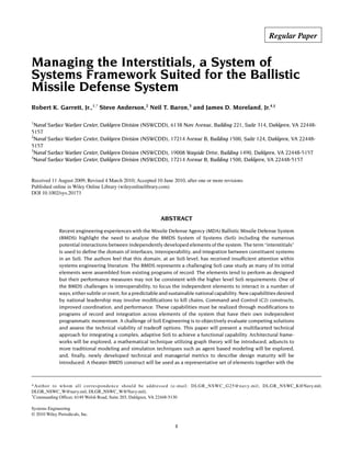
![interstitials representing the integration domain. Increased attention to the interstitial space of the
overarching BMDS SoS construct and applying appropriate technical rigor and engineering due diligence
with these added tools should greatly assist the BMDS in realizing its potential. © 2010 Wiley Periodicals,
Inc. Syst Eng
Key words: System of Systems; complexity; Ballistic Missile Defense; architecture; modeling and simula-
tion
1. INTRODUCTION
This paper, as written by naval defense engineering practitio-
ners, is an attempt at outreach to the larger academic and
industrial engineering community. The challenges in design-
ing and realizing very large scale technological machines of
war, with a U.S. Navy Aegis destroyer, an Aircraft Carrier,
and a multiservice National Ballistic Missile Defense capa-
bility being just a few examples, have been daunting to the
public and private defense industrial base as evidenced in
excessive cost overruns and schedule breaches of ongoing
programs. The vision of our political leaders is not being
realized by the technical community within agreeable budget
and schedule constraints. Large-scale warfare system devel-
opment can take a decade or more to realize, a timeline that
is often compounded by the dynamic needs of national de-
fense. We attempt in this paper to encourage investigation of
the potential utility of new perspectives, approaches, and tools
for the systems engineer. We believe that the concepts pre-
sented here will equip the systems engineer to better under-
stand and manage system complexity while engaged in the
design cycle as well as enhance the engineer’s ability to
communicate critical design attributes that drive the perform-
anceofsuchsystems.Wesuggestthattherichintellectualbase
already existing in areas such as network flow analysis and
system dynamics can be combined with new computational
approaches such as agent-based modeling to augment tradi-
tional systems engineering. We hope to encourage technical
discussion and debate on the development, use, and utility of
such tools with respect to the engineering of large scale
complex systems of systems for naval defense.
A theater BMDS is an example of a highly complex,
adaptive SoS that can be represented at any time using net-
work flow nomenclature. As such, individual systems can be
represented as nodes and the interactions between them by
edges. Using this graph theoretic approach offers an extensive
body of mathematical theory along with analysis methods that
allow the SoS to be analyzed in a coherent and comprehensive
manner. In practice, a BMDS SoS can be characterized by a
loosely coupled federation based on the local threat and
available assets. A key characteristic of any BMDS SoS is the
distributed Command and Control (C2) structure with com-
plex technical demands such as real-time fire control and
contrasting non-real-time planning and situational awareness.
The constituent systems tend to be well understood and rep-
resented by mature dynamic systems analysis, i.e., System
Dynamics (SD). Historically, each constituent shooter system
brings its own organic fire control system to the SoS. Inte-
grated fire control can be limited by the queuing of inde-
pendent sensors. If the theater BMDS/SoS were able to suc-
cessfully integrate fire control across all available land, sea,
and space-based sensors, the resulting capability should have
improved discrimination timelines to facilitate warfighting
constructs such as Engage on Remote (EoR) and Launch on
Remote (LoR) doctrine to improve the theater BMDS prob-
ability of raid annihilation. EoR is a distributed engagement
construct wherein the shooter system receives sensor input
solely from nonorganic sensors of sufficient quality to support
all phases of the ballistic missile engagement sequence. Guid-
ance updates to the interceptor are based solely on this nonor-
ganic sensor track. LoR is a similar distributed engagement
wherein the shooter receives sensor input from off-board
sensors of sufficient quality to launch an interceptor and
support flight operations until the shooter establishes its own
organic track of the target. The term organic is defined as the
items assigned to and forming an essential part of a military
organization [DoD, 2001] or more simply as an example, a
radar or missile launcher mounted on a specific ship. Fre-
quently, nonorganic components are developed inde-
pendently of the shooter system, usually by another program
office using different systems engineering processes, tools,
and techniques which presentsintegrationchallenges.Inother
words, we are entering a new era that requires the dynamic
integration of distributed detect, distributed control, and dis-
tributed engage features comprised of heterogeneous compo-
nents.
This paper will present a multi-faceted technical approach
for integrating a complex, adaptive SoS to achieve a func-
tional capability. The theater BMDS construct will be used as
an example of a highly complex, highly integrated SoS to
highlight the importance and dependency of the integration
domain, i.e., interstitial space, between elements of the SoS.
A means to represent the elements and the interstitial space
will be proposed with a mathematical analogy. The method-
ology proposed should assist in better understanding SoS
complexity. In addition to the appropriate use of traditional
SD, Agent-Based Modeling (ABM) is suggested as a tech-
nique to explore and quantify the interstitial behaviors. The
nascent concepts of Integration Readiness Level (IRL), Sys-
tem Readiness Level (SRL), and Enterprise Readiness Level
(ERL) will be described. We suggest that these concepts,
when considered in combination with the traditional Technol-
ogy Readiness Level (TRL), provide an initial subjective
metric to guide SoS integration and to quantify the notion of
SoS “maturity.”
This paper is one in a series of papers [Zilic and Baron,
2009; Moreland, 2009; Ormsby, 2008] developed by the
Naval Warfare Center to coalesce current thoughts on the
2 GARRETT ET AL.
Systems Engineering DOI 10.1002/sys](data:image/gif;base64,R0lGODlhAQABAIAAAAAAAP///yH5BAEAAAAALAAAAAABAAEAAAIBRAA7)