SlideShare a Scribd company logo
1 of 42
Download to read offline
ME8595 THERMAL ENGINEERING – II
UNIT I STEAM NOZZLE
Types and Shapes of nozzles, Flow of steam through nozzles, Critical pressure
ratio, Variation of mass flow rate with pressure ratio. Effect of friction.
Metastable flow.
UNIT II BOILERS
Types and comparison. Mountings and Accessories. Fuels - Solid, Liquid and
Gas. Performance calculations, Boiler trial.
UNIT III STEAM TURBINES
Types, Impulse and reaction principles, Velocity diagrams, Work done and
efficiency – optimal operating conditions. Multi-staging, compounding and
governing.
UNIT IV COGENERATION AND RESIDUAL HEAT RECOVERY
Cogeneration Principles, Cycle Analysis, Applications, Source and utilisation of
residual heat. Heat pipes, Heat pumps, Recuperative and Regenerative heat
exchangers. Economic Aspects.
UNIT V REFRIGERATION AND AIR – CONDITIONING
Vapour compression refrigeration cycle, Effect of Superheat and Sub-cooling,
Performance calculations, Working principle of air cycle, vapour absorption
system, and Thermoelectric refrigeration. Air conditioning systems, concept of
RSHF, GSHF and ESHF, Cooling load calculations. Cooling towers – concept
and types.
TOTAL:45 PERIODS
TEXT BOOKS:
1. Kothandaraman, C.P., Domkundwar .S and Domkundwar A.V.,”A course in
Thermal Engineering”, Dhanpat Rai & Sons, 2016.
2. Mahesh. M. Rathore, “Thermal Engineering”, 1st Edition, Tata Mc Graw Hill
Publications, 2010.
REFERENCES:
1. Arora .C.P., “Refrigeration and Air Conditioning”, Tata Mc Graw Hill, 2008
2. Ballaney. P.L ." Thermal Engineering”, Khanna publishers, 24th Edition
2012
3. Charles H Butler : Cogeneration” McGraw Hill, 1984.
4. Donald Q. Kern, “ Process Heat Transfer”, Tata Mc Graw Hill, 2001.
5. Sydney Reiter “Industrial and Commercial Heat Recovery Systems” Van
Nostrand Reinhols, 1985.
Visit for More : www.LearnEngineering.in
w
w
w
.
L
e
a
r
n
E
n
g
i
n
e
e
r
i
n
g
.
i
n
PREREQUISITE DISCUSSIONS
A steam turbine is basically an assembly of nozzles fixed to a stationary casing
and rotating blades mounted on the wheels attached on a shaft in a row-wise manner.
In 1878, a Swedish engineer, Carl G. P. de Laval developed a simple impulse turbine,
using a convergent-divergent (supersonic) nozzle which ran the turbine to a
maximum speed of 100,000 rpm. In 1897 he constructed a velocity-compounded
impulse turbine (a two-row axial turbine with a row of guide vane stators between
them.
Auguste Rateau in France started experiments with a de Laval turbine in 1894,
and developed the pressure compounded impulse turbine in the year 1900.
In the USA , Charles G. Curtis patented the velocity compounded de Lavel
turbine in 1896 and transferred his rights to General Electric in 1901.
In England , Charles A. Parsons developed a multi-stage axial flow reaction
turbine in
1884.
Steam turbines are employed as the prime movers together with the electric
generators in thermal and nuclear power plants to produce electricity. They are also
used to propel large ships, ocean liners, submarines and to drive power absorbing
machines like large compressors, blowers, fans and pumps.
Turbines can be condensing or non-condensing types depending on whether
the back pressure is below or equal to the atmosphere pressure.
STEAM NOZZLE
Introduction
A steam turbine converts the energy of high-pressure, high temperature steam
produced by a steam generator into shaft work. The energy conversion is brought
about in the following ways:
Visit for More : www.LearnEngineering.in
w
w
w
.
L
e
a
r
n
E
n
g
i
n
e
e
r
i
n
g
.
i
n
Unit 1
STEAM NOZZLE
1. The high-pressure, high-temperature steam first expands in the nozzles
emanates as a high velocity fluid stream.
2. The high velocity steam coming out of the nozzles impinges on the blades
mounted on a wheel. The fluid stream suffers a loss of momentum while
flowing past the blades that is absorbed by the rotating wheel entailing
production of torque.
3. The moving blades move as a result of the impulse of steam (caused by the
change of momentum) and also as a result of expansion and acceleration of
the steam relative to them. In other words they also act as the nozzles.
Flow Through Nozzles
A nozzle is a duct that increases the velocity of the flowing fluid at the expense
of pressure drop.

 A duct which decreases the velocity of a fluid and causes a corresponding
increase in pressure is a diffuser .

 The same duct may be either a nozzle or a diffuser depending upon the end
conditions across it. If the cross-section of a duct decreases gradually from inlet to
exit, the duct is said to be convergent.

 Conversely if the cross section increases gradually from the inlet to exit, the
duct is said to be divergent.

 If the cross-section initially decreases and then increases, the duct is called a
convergent-divergent nozzle.

The minimum cross-section of such ducts is known as throat.

 A fluid is said to be compressible if its density changes with the change in
pressure brought about by the flow.

Visit for More : www.LearnEngineering.in
w
w
w
.
L
e
a
r
n
E
n
g
i
n
e
e
r
i
n
g
.
i
n
 If the density does not changes or changes very little, the fluid is said to be
incompressible. Usually the gases and vapors are compressible, whereas liquids
are incompressible .

Shapes of nozzles
1. At subsonic speeds (Ma<1) a decrease in area increases the speed of flow.
2. In supersonic flows (Ma>1), the effect of area changes are different.
Convergent divergent nozzles
SIGNIFICANCE OF STEAM TURBINES
Large scale electrical energy production largely depends on the use of turbines.
Nearly all of the world's power that is supplied to a major grid is produced by
turbines.

Visit for More : www.LearnEngineering.in
w
w
w
.
L
e
a
r
n
E
n
g
i
n
e
e
r
i
n
g
.
i
n
 From steam turbines used at coal-burning electricity plants to liquid water
turbines used at hydro-electric plants, turbines are versatile and can be used
in a number of applications.

 There are also gas turbines that combust natural gas or diesel fuel for use in
remote locations or where a large backup power supply is required. Most
power plants use turbines to produce energy by burning coal or natural gas.

The heat produced from combustion is used to heat water in boiler. The liquid
water is converted to steam upon heating and is exhausted through a pipe
which feeds the steam to the turbine.

 The pressurized steam flow imparts energy on the blades and shaft of the
turbine causing it to rotate.

The rotational mechanical energy is then converted to electrical energy using
a generator.
STEAM TURBINES
Turbines
We shall consider steam as the working fluid
Single stage or Multistage
Axial or Radial turbines
Atmospheric discharge or discharge below atmosphere in condenser
Impulse/and Reaction turbine

Impulse Turbines
Impulse turbines (single-rotor or multirotor) are simple stages of the turbines.
Here the impulse blades are attached to the shaft.
Impulse blades can be recognized by their shape.
The impulse blades are short and have constant cross sections.
Schematic diagram of an Impulse Trubine
Visit for More : www.LearnEngineering.in
w
w
w
.
L
e
a
r
n
E
n
g
i
n
e
e
r
i
n
g
.
i
n
V1 and V2 = Inlet and outlet absolute velocity
Vr1 and V r2 = Inlet and outlet relative velocity (Velocity relative to the rotor blades.)
U = mean blade speed
= nozzle angle,
= absolute fluid angle at outlet
It is to be mentioned that all angles are with respect to the tangential velocity ( in the
direction of U )
Velocity diagram of an Impulse Turbine
Visit for More : www.LearnEngineering.in
w
w
w
.
L
e
a
r
n
E
n
g
i
n
e
e
r
i
n
g
.
i
n
The Single-Stage Impulse Turbine
 The single-stage impulse turbine is also called the de Laval turbine after its
inventor.
The turbine consists of a single rotor to which impulse blades are attached.

Visit for More : www.LearnEngineering.in
w
w
w
.
L
e
a
r
n
E
n
g
i
n
e
e
r
i
n
g
.
i
n
 The steam is fed through one or several convergent-divergent nozzles which
do not extend completely around the circumference of the rotor, so that only
part of the blades is impinged upon by the steam at any one time.
 The nozzles also allow governing of the turbine by shutting off one or more
them.
Compounding in Impulse Turbine
If high velocity of steam is allowed to flow through one row of moving blades,
it produces a rotor speed of about 30000 rpm which is too high for practical
use.

 It is essential to incorporate some improvements for practical use and also to
achieve high performance.

This is called compounding.

 Two types of compounding can be accomplished: (a) velocity compounding
and (b) pressure compounding

The Velocity - Compounding of the Impulse Turbine
 The velocity-compounded impulse turbine was first proposed to solve the
problems of a single-stage impulse turbine for use with high pressure and
temperature steam.

It is composed of one stage of nozzles as the single-stage turbine, followed by
two rows of moving blades instead of one.

These two rows are separated by one row of fixed blades attached to the turbine
stator, which has the function of redirecting the steam leaving the first row of
moving blades to the second row of moving blades.



Pressure Compounding or Rateau Staging
Visit for More : www.LearnEngineering.in
w
w
w
.
L
e
a
r
n
E
n
g
i
n
e
e
r
i
n
g
.
i
n
To alleviate the problem of high blade velocity in the single-stage impulse turbine,
the total enthalpy drop through the nozzles of that turbine are simply divided up,
essentially in an equal manner, among many single-stage impulse turbines in
series,Such a turbine is called a Rateau turbine.

The inlet steam velocities to each stage are essentially equal and due to a reduced
Δh.
Reaction Turbine
 A reaction turbine, therefore, is one that is constructed of rows of fixed and
rows of moving blades.

The fixed blades act as nozzles.

The moving blades move as a result of the impulse of steam received (caused
by change in momentum) and also as a result of expansion and acceleration
of the steam relative to them.
The pressure drops will not be equal.

They are greater for the fixed blades and greater for the high-pressure than the
low-pressure stages.

 The absolute steam velocity changes within each stage as shown and repeats
from stage to stage.
APPLICATIONS
Locomotives
Power generations
Industrial application for producing steam



Governing of Steam Turbine: The method of maintaining the turbine
speed constant irrespective of the load is known as governing of turbines. The device
Visit for More : www.LearnEngineering.in
w
w
w
.
L
e
a
r
n
E
n
g
i
n
e
e
r
i
n
g
.
i
n
used for governing of turbines is called Governor. There are 3 types of governors in
steam turbine,
1.Throttle governing
2.Nozzle governing
3.By-pass governing
i.Throttle Governing:
Let us consider an instant when the load on the turbine increases, as a result the speed
of the turbine decreases. The fly balls of the governor will come down. The fly balls
bring down the sleeve. The downward movement of the sleeve will raise the control
valve rod. The mouth of the pipe AA will open. Now the oil under pressure will rush
from the control valve to right side of piston in the rely cylinder through the pipe
AA. This will move the piston and spear towards the left which will open more area
of nozzle. As a result steam flow rate into the turbine increases, which in turn brings
the speed of the turbine to the normal range.
ii)Nozzle Governing:
Visit for More : www.LearnEngineering.in
w
w
w
.
L
e
a
r
n
E
n
g
i
n
e
e
r
i
n
g
.
i
n
A dynamic arrangement of nozzle control governing is shown in fig.
In this nozzles are grouped in 3 to 5 or more groups and each group of nozzle is
supplied steam controlled by valves. The arc of admission is limited to 180º or less.
The nozzle controlled governing is restricted to the first stage of the turbine, the
nozzle area in other stages remaining constant. It is suitable for the simple turbine
and for larger units which have an impulse stage followed by an impulse reaction
turbine.
Solved Problems:
1. A convergent divergent adiabatic steam nozzle is supplied with steam at 10 bar
and 250°c.the discharge pressure is 1.2 bar.assuming that the nozzle efficiency is
100% and initial velocity of steam is 50 m/s. find the discharge velocity.
Given Data:-
Initial pressure(p1)=10bar Initial
Temperature(T1)=250°c
Exit pressure(p2)=1.2 bar
Visit for More : www.LearnEngineering.in
w
w
w
.
L
e
a
r
n
E
n
g
i
n
e
e
r
i
n
g
.
i
n
Nozzle efficiency(ηnozzle)=100%
Initial velocity of steam (v1)=50m/s
To Find:-
Discharge velocity (v2)
Solution:-
From steam table, For 10 bar, 250°c, h1=2943 KJ/kg s1=6.926 KJ/kgk
From steam table, For 1.2 bar,
hf2 =439.3 KJ/kg ; hfg2=2244.1 KJ/kg;
sf2=1.3 61 KJ/kg K ; sfg2=5.937 KJ/kgK.
Since s1=s2,
S1=sf 2+x2sfg2
6.926=1.361+x2(5.937)
X2=0 .9373
We know that,
h2=hf2+x2hfg2
= 439.3+(0.9373)2244.1
h2 = 2542KJ/Kg
Exit velocity (V2) = Rt[(2000(2943) 2542) + 502]
= 896.91m/s.
Visit for More : www.LearnEngineering.in
w
w
w
.
L
e
a
r
n
E
n
g
i
n
e
e
r
i
n
g
.
i
n
2. Dry saturated steam at 6.5 bar with negligible velocity expands isentropically
in a convergent divergent nozzle to 1.4 bar and dryness fraction 0.956. De
termine the final velocity of steam from th e nozzle if 13% heat is loss in
friction. Find th e % reduction in the final velocity.
Given data:
Exit pressure (P2) = 1.4 bar
Dryness fract ion (X2) = 0.956
Heat loss = 13%
To Find:
The percent reduction in final velocity
Solution:
From steam table for initial pressure P1 = 6.5bar, take values h1 =
h1 = 2758.8KJ/Kg
Similarly, at 1.4 bar,
hfg2 = 2231.9 KJ/Kg
hf2 = 458.4KJ/Kg
h2 = hf2 + X2 hfg2
= 458.4 + (0.956) 2231.6
h2 = 2592.1 KJ/Kg
Final velocit y (V2) = Rt (2000(h1-h2) )
V2 = 577.39 m/s
Visit for More : www.LearnEngineering.in
w
w
w
.
L
e
a
r
n
E
n
g
i
n
e
e
r
i
n
g
.
i
n
Heat drop is 13%= 0.13
Nozzle efficiency (η) = 1- 0.13 = 0.87
Velocity of s team by considering the nozzle efficiency,
y (V2) = Rt (2000(h1-h2) ) x η
V2 = 538.55 m/s
= % reductio n in final velocity = 6.72%
3.A convergent divergent nozzle receives steam at 7bar and 200o
c and it ex
pands isentropically into a space of 3bar neglecting the inlet velocity calculat e the
exit area required for a mass flow of 0.1Kg/sec . when the flow is in equilibrium
through all and super saturated with PV1.3
=C.
Given Data:
Initiall pressure (P1) = 7bar = 7× 10⁵
N/m2
Initiall temperature (T1) = 200oC
Press ure (P2) = 3bar = 3× 10⁵N/m2
Mass flow rate (m) = 0.1Kg/sec
PV1.3
=C
To Find:
Exit area
Solution:
From st eam table for P1 = 7bar and T1 = 200oC V1 =
0.2999
h1 = 2844.2
Visit for More : www.LearnEngineering.in
w
w
w
.
L
e
a
r
n
E
n
g
i
n
e
e
r
i
n
g
.
i
n
S1 = 6.886
Similarly for P2 = 3bar
Vf2 = 0.001074 Vg2 = 0.60553 hf2 =
561.5 hfg2 = 2163.2
Sf2 = 1.672 Sfg2 = 5.319
We know that, S1 = S2 = St
S1 = Sf2 + X2 Sfg2
6.886 = 1.672 + X2 (5.319) X2 =
0.98
Similarly,
h2 = hf2 + X2 hfg2
h2 = 561.5 + 0.98 (2163.2)
(i) Flow is in equilibriu m through all:
V2=569.56
ν2 = X2 × νg2
= 0.98× 0.60553 = 0.5934
Visit for More : www.LearnEngineering.in
w
w
w
.
L
e
a
r
n
E
n
g
i
n
e
e
r
i
n
g
.
i
n
Visit for More : www.LearnEngineering.in
w
w
w
.
L
e
a
r
n
E
n
g
i
n
e
e
r
i
n
g
.
i
n
TECHNICAL TERMS
1.Diaphragm - Partitions b etween pressure stages in a turbine's casing.
2. Radial - flow turbine - st eam flows outward from the shaft to the casing.
3. Radial clearance - cleara nce at the tips of the rotor and casing.
4. Axial clearance - the fore -and-aft clearance, at the sides of the rotor and t he
casing.
5. balance piston - Instead of piston, seal strips are also used to duplicate a piston's
counter force.
6. steam rate - The steam rate is the pounds of steam that must be supplied per
kilowatt-hour of generator output at the steam turbine inlet.
Visit for More : www.LearnEngineering.in
w
w
w
.
L
e
a
r
n
E
n
g
i
n
e
e
r
i
n
g
.
i
n
7. extraction turbine - ste
am is withdrawn from one or more stages, at one or more pressures, for
heating, pl ant process, or feedwater heater needs.
8. Wet steam: The steam w hich contains some water particles in superposition.
9. Dry steam / dry saturated steam: When whole mass of steam is converted into
steam then it is called as dry steam.
10. Super heated steam: When the dry steam is further heated at consta nt pressure,
the temperature increases the above saturation temperature. The steam has obtained
is called super heated stea m.
11. Degree of super heat: The difference between the temperature of saturated steam
and saturated temperature is c alled degree of superheat.
12. Nozzle:It is a duct of varying cross sectional area in which the velocity increases
with the corresponding drop in pressure.
13. Coefficient of nozzle: It is the ratio of actual enthalpy drop to isentropic enthalpy
drop.
14. Critical pressure ratio: There is only one value of ratio (P2/P1) which
produces maximum discharge fro m the nozzle . then the ratio is called critica l
pressure ratio.
15. Degree of reaction: It is defined as the ratio of isentropic heat drop in th e moving
blade to isentrpic heat drop in the entire stages of the reaction turbine.
16. Compounding: It is the method of absorbing the jet velocity in stages when the
steam flows over moving blades. (i)Velocity compounding (ii)Pressure
compounding and (iii) Velocity-pressure compounding
17. Enthalpy: It is the combination of the internal energy and the flow energy.
18. Entropy: It is the function of quantity of heat with respective to the temperature.
19. Convergent nozzle: The crossectional area of the duct decreases from inlet to the
outlet side then it is called as convergent nozzle.
Visit for More : www.LearnEngineering.in
w
w
w
.
L
e
a
r
n
E
n
g
i
n
e
e
r
i
n
g
.
i
n
20. Divergent nozzle: The crossectional area of the duct increases from inlet to the
outlet then it is called as divergent nozzle.
Visit for More : www.LearnEngineering.in
w
w
w
.
L
e
a
r
n
E
n
g
i
n
e
e
r
i
n
g
.
i
n
SIGNIFICANCE OF STEAM TURBINES
Large scale electrical energy production largely depends on the use of turbines.
Nearly all of the world's power that is supplied to a major grid is produced by
turbines.

 From steam turbines used at coal-burning electricity plants to liquid water
turbines used at hydro-electric plants, turbines are versatile and can be used
in a number of applications.

 There are also gas turbines that combust natural gas or diesel fuel for use in
remote locations or where a large backup power supply is required. Most
power plants use turbines to produce energy by burning coal or natural gas.

The heat produced from combustion is used to heat water in boiler. The liquid
water is converted to steam upon heating and is exhausted through a pipe
which feeds the steam to the turbine.

 The pressurized steam flow imparts energy on the blades and shaft of the
turbine causing it to rotate.

The rotational mechanical energy is then converted to electrical energy using
a generator.
STEAM TURBINES
Turbines
We shall consider steam as the working fluid
Single stage or Multistage
Axial or Radial turbines
Atmospheric discharge or discharge below atmosphere in condenser
Impulse/and Reaction turbine

Impulse Turbines
Visit for More : www.LearnEngineering.in
w
w
w
.
L
e
a
r
n
E
n
g
i
n
e
e
r
i
n
g
.
i
n
Unit 3
Impulse turbines (single-rotor or multirotor) are simple stages of the turbines.
Here the impulse blades are attached to the shaft.
Impulse blades can be recognized by their shape.
The impulse blades are short and have constant cross sections.
Schematic diagram of an Impulse Trubine
V1 and V2 = Inlet and outlet absolute velocity
Vr1 and V r2 = Inlet and outlet relative velocity (Velocity relative to the rotor blades.)
U = mean blade speed
= nozzle angle,
= absolute fluid angle at outlet
It is to be mentioned that all angles are with respect to the tangential velocity ( in the
direction of U )
Velocity diagram of an Impulse Turbine
Visit for More : www.LearnEngineering.in
w
w
w
.
L
e
a
r
n
E
n
g
i
n
e
e
r
i
n
g
.
i
n
Visit for More : www.LearnEngineering.in
w
w
w
.
L
e
a
r
n
E
n
g
i
n
e
e
r
i
n
g
.
i
n
The Single-Stage Impulse Turbine
 The single-stage impulse turbine is also called the de Laval turbine after its
inventor.
The turbine consists of a single rotor to which impulse blades are attached.

 The steam is fed through one or several convergent-divergent nozzles which
do not extend completely around the circumference of the rotor, so that only
part of the blades is impinged upon by the steam at any one time.
 The nozzles also allow governing of the turbine by shutting off one or more
them.
Compounding in Impulse Turbine
If high velocity of steam is allowed to flow through one row of moving blades,
it produces a rotor speed of about 30000 rpm which is too high for practical
use.

 It is essential to incorporate some improvements for practical use and also to
achieve high performance.

This is called compounding.

 Two types of compounding can be accomplished: (a) velocity compounding
and (b) pressure compounding

The Velocity - Compounding of the Impulse Turbine
 The velocity-compounded impulse turbine was first proposed to solve the
problems of a single-stage impulse turbine for use with high pressure and
temperature steam.

It is composed of one stage of nozzles as the single-stage turbine, followed by
two rows of moving blades instead of one.

Visit for More : www.LearnEngineering.in
w
w
w
.
L
e
a
r
n
E
n
g
i
n
e
e
r
i
n
g
.
i
n
These two rows are separated by one row of fixed blades attached to the turbine
stator, which has the function of redirecting the steam leaving the first row of
moving blades to the second row of moving blades.



Pressure Compounding or Rateau Staging
To alleviate the problem of high blade velocity in the single-stage impulse turbine,
the total enthalpy drop through the nozzles of that turbine are simply divided up,
essentially in an equal manner, among many single-stage impulse turbines in
series,Such a turbine is called a Rateau turbine.

The inlet steam velocities to each stage are essentially equal and due to a reduced
Δh.
Reaction Turbine
 A reaction turbine, therefore, is one that is constructed of rows of fixed and
rows of moving blades.

The fixed blades act as nozzles.

The moving blades move as a result of the impulse of steam received (caused
by change in momentum) and also as a result of expansion and acceleration
of the steam relative to them.
The pressure drops will not be equal.

They are greater for the fixed blades and greater for the high-pressure than the
low-pressure stages.

 The absolute steam velocity changes within each stage as shown and repeats
from stage to stage.
APPLICATIONS
Visit for More : www.LearnEngineering.in
w
w
w
.
L
e
a
r
n
E
n
g
i
n
e
e
r
i
n
g
.
i
n
Locomotives
Power generations
Industrial application for producing steam



Governing of Steam Turbine: The method of maintaining the turbine
speed constant irrespective of the load is known as governing of turbines. The device
used for governing of turbines is called Governor. There are 3 types of governors in
steam turbine,
1.Throttle governing
2.Nozzle governing
3.By-pass governing
i.Throttle Governing:
Let us consider an instant when the load on the turbine increases, as a result the speed
of the turbine decreases. The fly balls of the governor will come down. The fly balls
bring down the sleeve. The downward movement of the sleeve will raise the control
valve rod. The mouth of the pipe AA will open. Now the oil under pressure will rush
from the control valve to right side of piston in the rely cylinder through the pipe
AA. This will move the piston and spear towards the left which will open more area
of nozzle. As a result steam flow rate into the turbine increases, which in turn brings
the speed of the turbine to the normal range.
Visit for More : www.LearnEngineering.in
w
w
w
.
L
e
a
r
n
E
n
g
i
n
e
e
r
i
n
g
.
i
n
ii)Nozzle Governing:
A dynamic arrangement of nozzle control governing is shown in fig.
In this nozzles are grouped in 3 to 5 or more groups and each group of nozzle is
supplied steam controlled by valves. The arc of admission is limited to 180º or less.
The nozzle controlled governing is restricted to the first stage of the turbine, the
nozzle area in other stages remaining constant. It is suitable for the simple turbine
and for larger units which have an impulse stage followed by an impulse reaction
turbine.
Visit for More : www.LearnEngineering.in
w
w
w
.
L
e
a
r
n
E
n
g
i
n
e
e
r
i
n
g
.
i
n
ME6404 THERMAL ENGINEERING
91
SCE Department of Mechanical Engineering
UNIT – 5
REFRIGERATION AND AIR CONDITIONING
5.1 PREREQUISITE DISCUSSION
Before 1830, few Americans used ice to refrigerate foods due to a lack of ice-
storehouses and iceboxes. As these two things became more widely available, individuals
used axes and saws to harvest ice for their storehouses. This method proved to be difficult,
dangerous, and certainly did not resemble anything that could be duplicated on a
commercial scale.
Despite the difficulties of harvesting ice, Frederic Tudor thought that he could
capitalize on this new commodity by harvesting ice in New England and shipping it to the
Caribbean islands as well as the southern states. In the beginning, Tudor lost thousands of
dollars, but eventually turned a profit as he constructed icehouses in Charleston, Virginia
and in the Cuban port town of Havana. These icehouses as well as better insulated ships
helped reduce ice wastage from 66% to 8%. This efficiency gain influenced Tudor to
expand his ice market to other towns with icehouses such as New Orleans and Savannah.
This ice market further expanded as harvesting ice became faster and cheaper after one of
Tudor’s suppliers, Nathaniel Wyeth, invented a horse-drawn ice cutter in 1825. This
invention as well as Tudor’s success inspired others to get involved in the ice trade and the
ice industry grew.
Ice became a mass-market commodity by the early 1830s with the price of ice
dropping from six cents per pound to a half of a cent per pound. In New York City, ice
consumption increased from 12,000 tons in 1843 to 100,000 tons in 1856. Boston’s
consumption leapt from 6,000 tons to 85,000 tons during that same period. Ice harvesting
created a “cooling culture” as majority of people used ice and iceboxes to store their dairy
products, fish, meat, and even fruits and vegetables. These early cold storage practices
paved the way for many Americans to accept the refrigeration technology that would soon
take over the country.
CONCEPT
5.2 CONCEPT OF REFRIGERATION
Refrigeration is a process in which work is done to move heat from one location to
another. The work of heat transport is traditionally driven by mechanical work, but can also
be driven by heat, magnetism, electricity, laser, or other means.
How does it work?
Visit for More : www.LearnEngineering.in
w
w
w
.
L
e
a
r
n
E
n
g
i
n
e
e
r
i
n
g
.
i
n
ME6404 THERMAL ENGINEERING
92
SCE Department of Mechanical Engineering
Thermal energy moves from left to right through five loops of heat transfer:
1) Indoor air loop
2) Chilled water loop
3) Refrigerant loop
4) Condenser water loop
5) Cooling water loop
5.3 SIGNIFICANCE
Refrigeration has had a large importance on industry, lifestyle, agriculture and
settlement patterns. The idea of preserving food dates back to the ancient Roman and
Chinese empires. However, refrigeration technology has rapidly evolved in the last
century, from ice harvesting to temperature-controlled rail cars. In order to avoid food
spoilage, refrigeration plays an important role in day to day life, similarly, Air conditioning
is also an important technological system to prevent the human from the hot atmosphere
during summer seasons.
5.4 CLASSIFICATION OF REFRIGERATION SYSTEM
Types of Refrigeration
• Vapour Compression Refrigeration (VCR): uses mechanical energy
• Vapour Absorption Refrigeration (VAR): uses thermal energy
5.5 VAPOUR COMPRESSION REFRIGERATION
• Highly compressed fluids tend to get colder when allowed to expand
• If pressure high enough
• Compressed air hotter than source of cooling
• Expanded gas cooler than desired cold temperature
• Lot of heat can be removed (lot of thermal energy to change liquid to vapour)
• Heat transfer rate remains high (temperature of working fluid much lower than
what is being cooled)
Visit for More : www.LearnEngineering.in
w
w
w
.
L
e
a
r
n
E
n
g
i
n
e
e
r
i
n
g
.
i
n
ME6404 THERMAL ENGINEERING
93
SCE Department of Mechanical Engineering
Vapour Compression Refrigeration Cycle
Evaporator
Low pressure liquid refrigerant in evaporator absorbs heat and changes to a gas
Compressor
The superheated vapour enters the compressor where its pressure is raised
Condenser
The high pressure superheated gas is cooled in several stages in the condenser
Expansion
Liquid passes through expansion device, which reduces its pressure and controls the
flow into the evaporator
Type of refrigerant
• Refrigerant determined by the required cooling temperature
• Chlorinated fluorocarbons (CFCs) or freons: R-11, R-12, R-21, R-22 and R-502
Choice of compressor, design of condenser, evaporator determined by
• Refrigerant
• Required cooling
• Load
• Ease of maintenance
• Physical space requirements
• Availability of utilities (water, power)
Visit for More : www.LearnEngineering.in
w
w
w
.
L
e
a
r
n
E
n
g
i
n
e
e
r
i
n
g
.
i
n
ME6404 THERMAL ENGINEERING
94
SCE Department of Mechanical Engineering
5.6 Vapour Absorption Refrigeration
Evaporator
Absorber
High pressure generator
ME6404 THERMAL ENGINEERING
94
SCE Department of Mechanical Engineering
5.6 Vapour Absorption Refrigeration
Evaporator
Absorber
High pressure generator
ME6404 THERMAL ENGINEERING
94
SCE Department of Mechanical Engineering
5.6 Vapour Absorption Refrigeration
Evaporator
Absorber
High pressure generator
Visit for More : www.LearnEngineering.in
w
w
w
.
L
e
a
r
n
E
n
g
i
n
e
e
r
i
n
g
.
i
n
ME6404 THERMAL ENGINEERING
95
SCE Department of Mechanical Engineering
Condenser
Evaporative Cooling
• Air in contact with water to cool it close to ‘wet bulb temperature’
• Advantage: efficient cooling at low cost
• Disadvantage: air is rich in moisture
5.7 COMPARISON BETWEEN VAPOR COMPRESSION AND ABSORPTION
SYSTEM
5.8 PERFORMANCE
Assessment of Refrigeration
• Cooling effect: Tons of Refrigeration
1 TR = 3024 kCal/hr heat rejected
• TR is assessed as:
TR = Q xCp x (Ti – To) / 3024
Visit for More : www.LearnEngineering.in
w
w
w
.
L
e
a
r
n
E
n
g
i
n
e
e
r
i
n
g
.
i
n
ME6404 THERMAL ENGINEERING
96
SCE Department of Mechanical Engineering
Q = mass flow rate of coolant in kg/hr
Cp = is coolant specific heat in kCal /kg °C
Ti = inlet, temperature of coolant to evaporator (chiller) in 0°C
To = outlet temperature of coolant from evaporator (chiller) in 0°C
Specific Power Consumption (kW/TR)
• Indicator of refrigeration system’s performance
• kW/TR of centralized chilled water system is sum of
• Compressor kW/TR
• Chilled water pump kW/TR
• Condenser water pump kW/TR
• Cooling tower fan kW/TR
Coefficient of Performance (COP)
• The performance of refrigerators and heat pumps is expressed in terms of
coefficient of performance (COP), defined as
•
Measure
• Airflow Q (m3/s) at Fan Coil Units (FCU) or Air Handling Units (AHU):
anemometer
• Air density  (kg/m3)
• Dry bulb and wet bulb temperature: psychrometer
• Enthalpy (kCal/kg) of inlet air (hin) and outlet air (Hout): psychrometric charts
5.9 APPLICATIONS OF REFRIGERATRION
 Metal workers
 Oil refineries
 Chemical plants
 Petrochemical plants
 Transporting temperature-sensitive foodstuffs
 Dairy products
Visit for More : www.LearnEngineering.in
w
w
w
.
L
e
a
r
n
E
n
g
i
n
e
e
r
i
n
g
.
i
n
ME6404 THERMAL ENGINEERING
97
SCE Department of Mechanical Engineering
AIR CONDITIONERS
5.10 CONCEPT OF AIR CONDITIONING
Air conditioning (often referred to as aircon, AC or A/C) is the process of altering
the properties of air (primarily temperatureand humidity) to more favourable conditions,
typically with the aim of distributing the conditioned air to an occupied space to
improve thermal comfort and indoor air quality.
5.11 TYPES OF AIR CONDITIONERS
• Room air conditioners
• Zoned Systems
• Unitary Systems
• Window Air-conditioning System
• Split Air-conditioning System
• Central air conditioning systems
5.11.1 ROOM AIR CONDITIONER
• Room air conditioners cool rooms rather than the entire home.
• Less expensive to operate than central units
• Their efficiency is generally lower than that of central air conditioners.
• Can be plugged into any 15- or 20-amp, 115-volt household circuit that is not
shared with any other major appliances
5.11.2 ZONED SYSTEMS
5.11.3 CENTRAL AIR CONDITIONING
• Circulate cool air through a system of supply and return ducts. Supply ducts and
registers (i.e., openings in the walls, floors, or ceilings covered by grills) carry
cooled air from the air conditioner to the home.
• This cooled air becomes warmer as it circulates through the home; then it flows
back to the central air conditioner through return ducts and registers
Visit for More : www.LearnEngineering.in
w
w
w
.
L
e
a
r
n
E
n
g
i
n
e
e
r
i
n
g
.
i
n
ME6404 THERMAL ENGINEERING
98
SCE Department of Mechanical Engineering
5.11.4 UNITARY SYSTEMS
A unitary air conditioning system comprises an outdoor unit including a
compressor for compressing a refrigerant, an outdoor heat exchanger for heat exchange
of the refrigerant and an expander connected to the outdoor heat exchanger, for
expanding the refrigerant; a duct installed inside a zone of a building; a central blower
unit having a heat exchanger connected to the outdoor unit through a first refrigerant
pipe and a blower for supplying the air heat-exchanged by the heat exchanger to the duct;
and an individual blower unit including a heat exchanger connected to the outdoor unit
through a second refrigerant pipe and a fan for sending the air heat exchanged by the
heat exchanger and disposed in a zone in the building, for individually cooling or heating
the zone. Accordingly, cooling or heating operation is performed on each zone of the
building, and simultaneously, additional individual heating or cooling operation can
be performed on a specific space, so that a cost can be reduced and cooling or
heating in the building can be efficiently performed.
5.11.5 WINDOW AIR-CONDITIONING SYSTEM
It is the most commonly used air conditioner for single rooms. In this air
conditioner all the components, namely the compressor, condenser, expansion valve or
coil, evaporator and cooling coil are enclosed in a single box. This unit is fitted in a slot
made in the wall of the room, or often a window sill. Windows air conditioners are one of
the most widely used types of air conditioners because they are the simplest form of the
air conditioning systems. Window air conditioner comprises of the rigid base on which all
Visit for More : www.LearnEngineering.in
w
w
w
.
L
e
a
r
n
E
n
g
i
n
e
e
r
i
n
g
.
i
n
ME6404 THERMAL ENGINEERING
99
SCE Department of Mechanical Engineering
the parts of the window air conditioner are assembled. The base is assembled inside the
casing which is fitted into the wall or the window of the room in which the air conditioner
is fitted. The whole assembly of the window air conditioner can be divided into two
compartments: the room side, which is also the cooling side and the outdoor side from
where the heat absorbed by the room air is liberated to the atmosphere. The room side and
outdoor side are separated from each other by an insulated partition enclosed inside the
window air conditioner assembly. In the front of the window air conditioner on the room
side there is beautifully decorated front panel on which the supply and return air
grills are fitted (the whole front panel itself is commonly called as front grill). The
louvers fitted in the supply air grills are adjustable so as to supply the air in desired
direction. There is also one opening in the grill that allows access to the Control panel or
operating panel in front of the window air conditioner.
TYPES OF CENTRAL AC
• split-system
• An outdoor metal cabinet contains the condenser and compressor, and an
indoor cabinet contains the evaporator
• Packaged
• The evaporator, condenser, and compressor are all located in one cabinet.
5.11.6 SPLIT AIR-CONDITIONING SYSTEM:
The split air conditioner comprises of two parts: the outdoor unit and the indoor
unit. The outdoor unit, fitted outside the room, houses components like the compressor,
condenser and expansion valve. The indoor unit comprises the evaporator or cooling
Visit for More : www.LearnEngineering.in
w
w
w
.
L
e
a
r
n
E
n
g
i
n
e
e
r
i
n
g
.
i
n
ME6404 THERMAL ENGINEERING
100
SCE Department of Mechanical Engineering
coil and the cooling fan. For this unit you don't have to make any slot in the wall of
the room. Further, the present day split units have aesthetic looks and add to the beauty
of the room. The split air conditioner can be used to cool one or two rooms.
Energy Consumption
• Air conditioners are rated by the number of British Thermal Units (Btu) of heat
they can remove per hour. Another common rating term for air conditioning size is
the "ton," which is 12,000 Btu per hour.
• Room air conditioners range from 5,500 Btu per hour to 14,000 Btu per hour.
Energy Efficiency
• Today's best air conditioners use 30% to 50% less energy than 1970s
• Even if your air conditioner is only 10 years old, you may save 20% to 40% of your
cooling energy costs by replacing it with a newer, more efficient model
Visit for More : www.LearnEngineering.in
w
w
w
.
L
e
a
r
n
E
n
g
i
n
e
e
r
i
n
g
.
i
n
ME6404 THERMAL ENGINEERING
101
SCE Department of Mechanical Engineering
5.12 SOLVED PROBLEMS
1. A sling psychrometer gives reading of 250c dry bulb temperature 150c wet bulb
temperature. The barometer indicates 760 mm of hg assuming partial pressure of the
vapour as 10 mm of Hg. Determine 1. Specific humidity 2. Saturation ratio.
Given Data:
Dry bulb temperature td =250c
Wet bulb temperature tw=150c
Barometer pressure pb=760mm
of Hg
Partial pressure pv= 10mm of Hg
To Find:
Specific humidity
Saturation ratio.
Solution:
Specific humidity:
We know that Specific humidity
W =
0.0083 kg/kg of
dry air
Saturation ratio:
From steam table corresponding to dry bulb temperature td =250c
We find the partial pressure ps=0.03166 bar
=
=23.8 mm of Hg
Visit for More : www.LearnEngineering.in
w
w
w
.
L
e
a
r
n
E
n
g
i
n
e
e
r
i
n
g
.
i
n
ME6404 THERMAL ENGINEERING
102
SCE Department of Mechanical Engineering
We know that Saturation ratio.
µ=
=
= 0.41
Result:
1. Specific humidity 0.0083 kg/kg of dry air
2. Saturation ratio. = 0.41
2. A two stages, single acting air compressor compresses air to 20bar. The air enters
the
L.P cylinder at 1bar and 27oc and leaves it at 4.7bar. the air enters the H.P.
cylinder at
4.5bar and 27oc. the size of the L.P cylinder is 400mm diameter and 500mm stroke.
The clearance volume In both cylinder is 4% of the respective stroke volume. The
compressor runs at 200rpm, taking index of compression and expansion in the two
cylinders as 1.3, estimate 1. The indicated power required to run the compressor; and
2. The heat rejected in the intercooler per minute.
Given data:
Pressure (P4)= 20bar
Pressure (P1) = 1bar = 1×10⁵ N/m2
Temperature (T1) = 27oC = 27+273 =
300K Pressure (P2) = 4.7bar
Pressure (P3) = 4.5bar
Temperature (T3) = 27oC = 27+273 =
300K Diameter (D1) = 400mm 0.4m
Stroke (L1) = 500mm = 0.5m
N = 200rpm ; n = 1.3
To Find:
Indicated power required to run the compressor
Solution :
Visit for More : www.LearnEngineering.in
w
w
w
.
L
e
a
r
n
E
n
g
i
n
e
e
r
i
n
g
.
i
n
ME6404 THERMAL ENGINEERING
103
SCE Department of Mechanical Engineering
We know the swept volume of the L.P cylinder
= 0.06284 m3
And volumetric efficiency,
ηv
= 0.9085 or 90.85% Volume of air sucked by air pressure compressor,
=1.42 m3/min
And volume of air sucked by H.P compressor,
We know that indicated work done by L.P compressor
= 2123.3×103 J/min = 2123.3 KJ/min
And indicated workdone by H.P compressor,
Visit for More : www.LearnEngineering.in
w
w
w
.
L
e
a
r
n
E
n
g
i
n
e
e
r
i
n
g
.
i
n
ME6404 THERMAL ENGINEERING
104
SCE Department of Mechanical Engineering
= 2043.5×103 J/min = 2034.5 KJ/min
Total indicated work done by the compressor,
W = WL + WH = 2123.3 + 2034.5
= 4157.8 KJ/min
Indicated power required to run the compressor = 4157.8 / 60
= 69.3KW
3. In an oil gas turbine installation , air is taken as 1 bar and 30oC . The air is compressed
to 4bar and then heated by burning the oil to a temperature of 500oC . If the air flows at
the rate of 90Kg/min . Find the power developed by the plant take γ for air as 1.4 Cp as
1KJ/KgK . If 2.4Kg of oil having calorific value of 40,000 KJ/Kg if burned in the
combustion chamber per minute. Find the overall efficiency of the plant.
Given Data:
Pressure (P4 = P3) = 1bar
Pressure (P1 = P2) = 4bar
Temperature (T2) = 500oC = 500+273 = 773K
Mass flow rate of air(ma) = 90Kg/min = 1.5Kg/sec
Mass flow rate of fuel (mf) = 2.4Kg/min = 0.04Kg/sec
Temperature (T4) = 30oC = 30+273 = 303K
γ = 1.4 ; Cp = 1KJ/KgK ; Cv= 40,000 KJ/Kg
To Find:
Power developed by the plant
Performance of the gas turbine
Overall efficiency of the plant
Solution:
Visit for More : www.LearnEngineering.in
w
w
w
.
L
e
a
r
n
E
n
g
i
n
e
e
r
i
n
g
.
i
n
ME6404 THERMAL ENGINEERING
105
SCE Department of Mechanical Engineering
Power developed by the plant:
Let T1,T3 = temperature of air at points 1 and3
Weknow that isentropic expansion 2-3,
T3 = T2× 0.673 = 773×0.673 = 520K
Similarly for isentropic compression 4-1:
T1 = T4/ 0.673 = 303/0.673 = 450K
Performance of the gas turbine:
We know that work developed by the turbine,
= 379.5KJ/s
And work developed by the compressor,
= 220.5/s
Net work or power of the turbine,
P = WT - Wc = 379.5 – 220.5 = 159KJ/s = 159KW
Overall efficiency of the plant:
We know that the heat supplied per second
= mf × C = 0.04× 40,000 = 1600 KJ/s
Therefore, overall efficiency of the plant,
ηo = 159/1600 = 0.099 or 9.99%
Visit for More : www.LearnEngineering.in
w
w
w
.
L
e
a
r
n
E
n
g
i
n
e
e
r
i
n
g
.
i
n
106
5.13 TECHNICAL TERMS
BTU - British thermal unit. A unit of heat energy - approximately the amount of energy needed
to heat one pound of water by one degree Fahrenheit.
dBA – a unit for measuring sound power or pressure, deciBel on the A scale.
Capacity – the ability of a heating or cooling system to heat or cool a given amount of space.
For heating, this is usually expressed in BTU’s. For cooling, it is usually given in tons.
Compressor – the pump that moves the refrigerant from the indoor evaporator to the outdoor
condenser and back to the evaporator again. The compressor is often called “the heart of the
system” because it circulates the refrigerant through the loop.
Condenser – a device used to condense a refrigerant thereby rejecting the heat to another source,
typically an air cooled or water cooled condenser.
Cassette – a fan coil unit that fits mainly in the ceiling void with only a diffuser plate visible,
diffuses conditioned air in one, two, three or four directions.
HVAC – heating, ventilation and air conditioning.
Inverter system – Constantly alters fan and motor speeds. This enables faster cooling of a room,
and the inverter air conditioner doesn’t have to switch itself on and off to maintain a constant
temperature.
kw – standard measurement of heat or power, 1kw = 1000 watts = 3412Btu/hr = 860kcal.
Load Calculation – a mathematical design tool used to determine the heat gain and heat loss in
a building so that properly sized air conditioning and heating equipment may be installed.
Refrigerant – a substance that produces a refrigerating effect while expanding or vaporizing.
Reverse cycle – the reverse cycle air conditioner internally reverses its operation to provide
heating or cooling, as required.
Split System – a central air conditioner consisting of two or more major components. The
system usually consists of a compressor-containing unit and condenser, installed outside the
building and a non-compressor – containing air handling unit installed within the building. This
is the most common type of system installed in a home.
Zoning – the practice of providing independent heating and/or cooling to different areas in a
structure. Zoning typically utilizes a system controller, zoning dampers controlled by a
thermostat in each zone, and a bypass damper to regulate static pressure in the supply duct.
Visit for More : www.LearnEngineering.in
w
w
w
.
L
e
a
r
n
E
n
g
i
n
e
e
r
i
n
g
.
i
n

More Related Content

What's hot (20)

Turbomachinery presentation
Turbomachinery presentationTurbomachinery presentation
Turbomachinery presentation
 
Axial Flow Compressor.
Axial Flow Compressor. Axial Flow Compressor.
Axial Flow Compressor.
 
Impulse turbine
Impulse turbineImpulse turbine
Impulse turbine
 
STEAM POWER PLANT
STEAM POWER PLANTSTEAM POWER PLANT
STEAM POWER PLANT
 
Performance of ic engine
Performance of ic enginePerformance of ic engine
Performance of ic engine
 
Governor
GovernorGovernor
Governor
 
Velocity Triangle for Moving Blade of an impulse Turbine
Velocity Triangle for Moving Blade of an impulse TurbineVelocity Triangle for Moving Blade of an impulse Turbine
Velocity Triangle for Moving Blade of an impulse Turbine
 
Gas Turbine PPT
Gas Turbine PPTGas Turbine PPT
Gas Turbine PPT
 
[PPT] on Steam Turbine
[PPT] on Steam Turbine[PPT] on Steam Turbine
[PPT] on Steam Turbine
 
Governor and its type
Governor and its typeGovernor and its type
Governor and its type
 
Construction and manufacturing of steam turbine
Construction and manufacturing of steam turbineConstruction and manufacturing of steam turbine
Construction and manufacturing of steam turbine
 
ROTARY COMPRESSORS
ROTARY COMPRESSORSROTARY COMPRESSORS
ROTARY COMPRESSORS
 
Condenser and its types
Condenser and its types Condenser and its types
Condenser and its types
 
Steam turbine
Steam turbineSteam turbine
Steam turbine
 
Flywheel and governors
Flywheel and governorsFlywheel and governors
Flywheel and governors
 
Impulse and reaction turbines
Impulse and reaction turbinesImpulse and reaction turbines
Impulse and reaction turbines
 
air standard, fuel air and actual cycles
air standard, fuel air and actual cyclesair standard, fuel air and actual cycles
air standard, fuel air and actual cycles
 
Turbo machines basics slideshare
Turbo machines basics slideshareTurbo machines basics slideshare
Turbo machines basics slideshare
 
Steam turbine
Steam turbineSteam turbine
Steam turbine
 
Turbine.ppt
Turbine.pptTurbine.ppt
Turbine.ppt
 

Similar to Me8595 thermal engineering – ii

Turbomachinery Turbine pump Compressor.ppt
Turbomachinery Turbine pump Compressor.pptTurbomachinery Turbine pump Compressor.ppt
Turbomachinery Turbine pump Compressor.pptsbpatalescoe
 
UNIT-III_Steam_Turbine (1).pdf
UNIT-III_Steam_Turbine (1).pdfUNIT-III_Steam_Turbine (1).pdf
UNIT-III_Steam_Turbine (1).pdfManivannan727901
 
MODULE-V_STEAM TURBINES.pptx
MODULE-V_STEAM TURBINES.pptxMODULE-V_STEAM TURBINES.pptx
MODULE-V_STEAM TURBINES.pptxDhruvBagade
 
intern turbines-ppt finall (2).pptx
intern turbines-ppt finall (2).pptxintern turbines-ppt finall (2).pptx
intern turbines-ppt finall (2).pptxbobbaSaikiranreddy
 
A Report on Steam Turbine
A Report on Steam TurbineA Report on Steam Turbine
A Report on Steam TurbineRajput Chauhan
 
Steam Turbine_edit.pptx
Steam Turbine_edit.pptxSteam Turbine_edit.pptx
Steam Turbine_edit.pptxKrishhGupta
 
SFEE and steady flow engineering devices
SFEE and steady flow engineering devicesSFEE and steady flow engineering devices
SFEE and steady flow engineering devicesManoj Kumar
 
Turbine.....Samriddha Shil.....S@S
Turbine.....Samriddha Shil.....S@STurbine.....Samriddha Shil.....S@S
Turbine.....Samriddha Shil.....S@SSamriddha Shil
 
Turbine and it's classification.pptx
Turbine and it's classification.pptxTurbine and it's classification.pptx
Turbine and it's classification.pptxUmar Saeed
 
STEAM AND GAS TURBINES ppt
STEAM AND GAS TURBINES pptSTEAM AND GAS TURBINES ppt
STEAM AND GAS TURBINES pptANKIT GUPTA
 
Turbomachinery me-5001
Turbomachinery me-5001Turbomachinery me-5001
Turbomachinery me-5001Tasnim Arif
 

Similar to Me8595 thermal engineering – ii (20)

ME 6404 THERMAL ENGINEERING UNIT III
ME 6404 THERMAL ENGINEERING UNIT IIIME 6404 THERMAL ENGINEERING UNIT III
ME 6404 THERMAL ENGINEERING UNIT III
 
Turbomachinery Turbine pump Compressor.ppt
Turbomachinery Turbine pump Compressor.pptTurbomachinery Turbine pump Compressor.ppt
Turbomachinery Turbine pump Compressor.ppt
 
UNIT-III_Steam_Turbine (1).pdf
UNIT-III_Steam_Turbine (1).pdfUNIT-III_Steam_Turbine (1).pdf
UNIT-III_Steam_Turbine (1).pdf
 
bhel_report_STM
bhel_report_STMbhel_report_STM
bhel_report_STM
 
MODULE-V_STEAM TURBINES.pptx
MODULE-V_STEAM TURBINES.pptxMODULE-V_STEAM TURBINES.pptx
MODULE-V_STEAM TURBINES.pptx
 
intern turbines-ppt finall (2).pptx
intern turbines-ppt finall (2).pptxintern turbines-ppt finall (2).pptx
intern turbines-ppt finall (2).pptx
 
Steam turbine
Steam turbineSteam turbine
Steam turbine
 
Internship Report
Internship ReportInternship Report
Internship Report
 
A Report on Steam Turbine
A Report on Steam TurbineA Report on Steam Turbine
A Report on Steam Turbine
 
Steam Turbine_edit.pptx
Steam Turbine_edit.pptxSteam Turbine_edit.pptx
Steam Turbine_edit.pptx
 
steam turbine.pptx
steam turbine.pptxsteam turbine.pptx
steam turbine.pptx
 
SFEE and steady flow engineering devices
SFEE and steady flow engineering devicesSFEE and steady flow engineering devices
SFEE and steady flow engineering devices
 
Turbine.....Samriddha Shil.....S@S
Turbine.....Samriddha Shil.....S@STurbine.....Samriddha Shil.....S@S
Turbine.....Samriddha Shil.....S@S
 
Turbine and it's classification.pptx
Turbine and it's classification.pptxTurbine and it's classification.pptx
Turbine and it's classification.pptx
 
TM Module 2
TM Module 2TM Module 2
TM Module 2
 
Ppt of turbine
Ppt of turbinePpt of turbine
Ppt of turbine
 
Turbines
TurbinesTurbines
Turbines
 
Energy conversion devices 01-02
Energy conversion devices  01-02Energy conversion devices  01-02
Energy conversion devices 01-02
 
STEAM AND GAS TURBINES ppt
STEAM AND GAS TURBINES pptSTEAM AND GAS TURBINES ppt
STEAM AND GAS TURBINES ppt
 
Turbomachinery me-5001
Turbomachinery me-5001Turbomachinery me-5001
Turbomachinery me-5001
 

Recently uploaded

microprocessor 8085 and its interfacing
microprocessor 8085  and its interfacingmicroprocessor 8085  and its interfacing
microprocessor 8085 and its interfacingjaychoudhary37
 
ZXCTN 5804 / ZTE PTN / ZTE POTN / ZTE 5804 PTN / ZTE POTN 5804 ( 100/200 GE Z...
ZXCTN 5804 / ZTE PTN / ZTE POTN / ZTE 5804 PTN / ZTE POTN 5804 ( 100/200 GE Z...ZXCTN 5804 / ZTE PTN / ZTE POTN / ZTE 5804 PTN / ZTE POTN 5804 ( 100/200 GE Z...
ZXCTN 5804 / ZTE PTN / ZTE POTN / ZTE 5804 PTN / ZTE POTN 5804 ( 100/200 GE Z...ZTE
 
Application of Residue Theorem to evaluate real integrations.pptx
Application of Residue Theorem to evaluate real integrations.pptxApplication of Residue Theorem to evaluate real integrations.pptx
Application of Residue Theorem to evaluate real integrations.pptx959SahilShah
 
(ANVI) Koregaon Park Call Girls Just Call 7001035870 [ Cash on Delivery ] Pun...
(ANVI) Koregaon Park Call Girls Just Call 7001035870 [ Cash on Delivery ] Pun...(ANVI) Koregaon Park Call Girls Just Call 7001035870 [ Cash on Delivery ] Pun...
(ANVI) Koregaon Park Call Girls Just Call 7001035870 [ Cash on Delivery ] Pun...ranjana rawat
 
APPLICATIONS-AC/DC DRIVES-OPERATING CHARACTERISTICS
APPLICATIONS-AC/DC DRIVES-OPERATING CHARACTERISTICSAPPLICATIONS-AC/DC DRIVES-OPERATING CHARACTERISTICS
APPLICATIONS-AC/DC DRIVES-OPERATING CHARACTERISTICSKurinjimalarL3
 
HARMONY IN THE HUMAN BEING - Unit-II UHV-2
HARMONY IN THE HUMAN BEING - Unit-II UHV-2HARMONY IN THE HUMAN BEING - Unit-II UHV-2
HARMONY IN THE HUMAN BEING - Unit-II UHV-2RajaP95
 
High Profile Call Girls Nagpur Meera Call 7001035870 Meet With Nagpur Escorts
High Profile Call Girls Nagpur Meera Call 7001035870 Meet With Nagpur EscortsHigh Profile Call Girls Nagpur Meera Call 7001035870 Meet With Nagpur Escorts
High Profile Call Girls Nagpur Meera Call 7001035870 Meet With Nagpur EscortsCall Girls in Nagpur High Profile
 
Gurgaon ✡️9711147426✨Call In girls Gurgaon Sector 51 escort service
Gurgaon ✡️9711147426✨Call In girls Gurgaon Sector 51 escort serviceGurgaon ✡️9711147426✨Call In girls Gurgaon Sector 51 escort service
Gurgaon ✡️9711147426✨Call In girls Gurgaon Sector 51 escort servicejennyeacort
 
Gfe Mayur Vihar Call Girls Service WhatsApp -> 9999965857 Available 24x7 ^ De...
Gfe Mayur Vihar Call Girls Service WhatsApp -> 9999965857 Available 24x7 ^ De...Gfe Mayur Vihar Call Girls Service WhatsApp -> 9999965857 Available 24x7 ^ De...
Gfe Mayur Vihar Call Girls Service WhatsApp -> 9999965857 Available 24x7 ^ De...srsj9000
 
IVE Industry Focused Event - Defence Sector 2024
IVE Industry Focused Event - Defence Sector 2024IVE Industry Focused Event - Defence Sector 2024
IVE Industry Focused Event - Defence Sector 2024Mark Billinghurst
 
Sachpazis Costas: Geotechnical Engineering: A student's Perspective Introduction
Sachpazis Costas: Geotechnical Engineering: A student's Perspective IntroductionSachpazis Costas: Geotechnical Engineering: A student's Perspective Introduction
Sachpazis Costas: Geotechnical Engineering: A student's Perspective IntroductionDr.Costas Sachpazis
 
Current Transformer Drawing and GTP for MSETCL
Current Transformer Drawing and GTP for MSETCLCurrent Transformer Drawing and GTP for MSETCL
Current Transformer Drawing and GTP for MSETCLDeelipZope
 
Decoding Kotlin - Your guide to solving the mysterious in Kotlin.pptx
Decoding Kotlin - Your guide to solving the mysterious in Kotlin.pptxDecoding Kotlin - Your guide to solving the mysterious in Kotlin.pptx
Decoding Kotlin - Your guide to solving the mysterious in Kotlin.pptxJoão Esperancinha
 
(MEERA) Dapodi Call Girls Just Call 7001035870 [ Cash on Delivery ] Pune Escorts
(MEERA) Dapodi Call Girls Just Call 7001035870 [ Cash on Delivery ] Pune Escorts(MEERA) Dapodi Call Girls Just Call 7001035870 [ Cash on Delivery ] Pune Escorts
(MEERA) Dapodi Call Girls Just Call 7001035870 [ Cash on Delivery ] Pune Escortsranjana rawat
 
Call Girls Delhi {Jodhpur} 9711199012 high profile service
Call Girls Delhi {Jodhpur} 9711199012 high profile serviceCall Girls Delhi {Jodhpur} 9711199012 high profile service
Call Girls Delhi {Jodhpur} 9711199012 high profile servicerehmti665
 
Sheet Pile Wall Design and Construction: A Practical Guide for Civil Engineer...
Sheet Pile Wall Design and Construction: A Practical Guide for Civil Engineer...Sheet Pile Wall Design and Construction: A Practical Guide for Civil Engineer...
Sheet Pile Wall Design and Construction: A Practical Guide for Civil Engineer...Dr.Costas Sachpazis
 
Microscopic Analysis of Ceramic Materials.pptx
Microscopic Analysis of Ceramic Materials.pptxMicroscopic Analysis of Ceramic Materials.pptx
Microscopic Analysis of Ceramic Materials.pptxpurnimasatapathy1234
 

Recently uploaded (20)

microprocessor 8085 and its interfacing
microprocessor 8085  and its interfacingmicroprocessor 8085  and its interfacing
microprocessor 8085 and its interfacing
 
ZXCTN 5804 / ZTE PTN / ZTE POTN / ZTE 5804 PTN / ZTE POTN 5804 ( 100/200 GE Z...
ZXCTN 5804 / ZTE PTN / ZTE POTN / ZTE 5804 PTN / ZTE POTN 5804 ( 100/200 GE Z...ZXCTN 5804 / ZTE PTN / ZTE POTN / ZTE 5804 PTN / ZTE POTN 5804 ( 100/200 GE Z...
ZXCTN 5804 / ZTE PTN / ZTE POTN / ZTE 5804 PTN / ZTE POTN 5804 ( 100/200 GE Z...
 
Application of Residue Theorem to evaluate real integrations.pptx
Application of Residue Theorem to evaluate real integrations.pptxApplication of Residue Theorem to evaluate real integrations.pptx
Application of Residue Theorem to evaluate real integrations.pptx
 
(ANVI) Koregaon Park Call Girls Just Call 7001035870 [ Cash on Delivery ] Pun...
(ANVI) Koregaon Park Call Girls Just Call 7001035870 [ Cash on Delivery ] Pun...(ANVI) Koregaon Park Call Girls Just Call 7001035870 [ Cash on Delivery ] Pun...
(ANVI) Koregaon Park Call Girls Just Call 7001035870 [ Cash on Delivery ] Pun...
 
APPLICATIONS-AC/DC DRIVES-OPERATING CHARACTERISTICS
APPLICATIONS-AC/DC DRIVES-OPERATING CHARACTERISTICSAPPLICATIONS-AC/DC DRIVES-OPERATING CHARACTERISTICS
APPLICATIONS-AC/DC DRIVES-OPERATING CHARACTERISTICS
 
HARMONY IN THE HUMAN BEING - Unit-II UHV-2
HARMONY IN THE HUMAN BEING - Unit-II UHV-2HARMONY IN THE HUMAN BEING - Unit-II UHV-2
HARMONY IN THE HUMAN BEING - Unit-II UHV-2
 
High Profile Call Girls Nagpur Meera Call 7001035870 Meet With Nagpur Escorts
High Profile Call Girls Nagpur Meera Call 7001035870 Meet With Nagpur EscortsHigh Profile Call Girls Nagpur Meera Call 7001035870 Meet With Nagpur Escorts
High Profile Call Girls Nagpur Meera Call 7001035870 Meet With Nagpur Escorts
 
Gurgaon ✡️9711147426✨Call In girls Gurgaon Sector 51 escort service
Gurgaon ✡️9711147426✨Call In girls Gurgaon Sector 51 escort serviceGurgaon ✡️9711147426✨Call In girls Gurgaon Sector 51 escort service
Gurgaon ✡️9711147426✨Call In girls Gurgaon Sector 51 escort service
 
Gfe Mayur Vihar Call Girls Service WhatsApp -> 9999965857 Available 24x7 ^ De...
Gfe Mayur Vihar Call Girls Service WhatsApp -> 9999965857 Available 24x7 ^ De...Gfe Mayur Vihar Call Girls Service WhatsApp -> 9999965857 Available 24x7 ^ De...
Gfe Mayur Vihar Call Girls Service WhatsApp -> 9999965857 Available 24x7 ^ De...
 
IVE Industry Focused Event - Defence Sector 2024
IVE Industry Focused Event - Defence Sector 2024IVE Industry Focused Event - Defence Sector 2024
IVE Industry Focused Event - Defence Sector 2024
 
Sachpazis Costas: Geotechnical Engineering: A student's Perspective Introduction
Sachpazis Costas: Geotechnical Engineering: A student's Perspective IntroductionSachpazis Costas: Geotechnical Engineering: A student's Perspective Introduction
Sachpazis Costas: Geotechnical Engineering: A student's Perspective Introduction
 
Current Transformer Drawing and GTP for MSETCL
Current Transformer Drawing and GTP for MSETCLCurrent Transformer Drawing and GTP for MSETCL
Current Transformer Drawing and GTP for MSETCL
 
Decoding Kotlin - Your guide to solving the mysterious in Kotlin.pptx
Decoding Kotlin - Your guide to solving the mysterious in Kotlin.pptxDecoding Kotlin - Your guide to solving the mysterious in Kotlin.pptx
Decoding Kotlin - Your guide to solving the mysterious in Kotlin.pptx
 
Exploring_Network_Security_with_JA3_by_Rakesh Seal.pptx
Exploring_Network_Security_with_JA3_by_Rakesh Seal.pptxExploring_Network_Security_with_JA3_by_Rakesh Seal.pptx
Exploring_Network_Security_with_JA3_by_Rakesh Seal.pptx
 
(MEERA) Dapodi Call Girls Just Call 7001035870 [ Cash on Delivery ] Pune Escorts
(MEERA) Dapodi Call Girls Just Call 7001035870 [ Cash on Delivery ] Pune Escorts(MEERA) Dapodi Call Girls Just Call 7001035870 [ Cash on Delivery ] Pune Escorts
(MEERA) Dapodi Call Girls Just Call 7001035870 [ Cash on Delivery ] Pune Escorts
 
Call Girls Delhi {Jodhpur} 9711199012 high profile service
Call Girls Delhi {Jodhpur} 9711199012 high profile serviceCall Girls Delhi {Jodhpur} 9711199012 high profile service
Call Girls Delhi {Jodhpur} 9711199012 high profile service
 
Sheet Pile Wall Design and Construction: A Practical Guide for Civil Engineer...
Sheet Pile Wall Design and Construction: A Practical Guide for Civil Engineer...Sheet Pile Wall Design and Construction: A Practical Guide for Civil Engineer...
Sheet Pile Wall Design and Construction: A Practical Guide for Civil Engineer...
 
young call girls in Rajiv Chowk🔝 9953056974 🔝 Delhi escort Service
young call girls in Rajiv Chowk🔝 9953056974 🔝 Delhi escort Serviceyoung call girls in Rajiv Chowk🔝 9953056974 🔝 Delhi escort Service
young call girls in Rajiv Chowk🔝 9953056974 🔝 Delhi escort Service
 
9953056974 Call Girls In South Ex, Escorts (Delhi) NCR.pdf
9953056974 Call Girls In South Ex, Escorts (Delhi) NCR.pdf9953056974 Call Girls In South Ex, Escorts (Delhi) NCR.pdf
9953056974 Call Girls In South Ex, Escorts (Delhi) NCR.pdf
 
Microscopic Analysis of Ceramic Materials.pptx
Microscopic Analysis of Ceramic Materials.pptxMicroscopic Analysis of Ceramic Materials.pptx
Microscopic Analysis of Ceramic Materials.pptx
 

Me8595 thermal engineering – ii

  • 1. ME8595 THERMAL ENGINEERING – II UNIT I STEAM NOZZLE Types and Shapes of nozzles, Flow of steam through nozzles, Critical pressure ratio, Variation of mass flow rate with pressure ratio. Effect of friction. Metastable flow. UNIT II BOILERS Types and comparison. Mountings and Accessories. Fuels - Solid, Liquid and Gas. Performance calculations, Boiler trial. UNIT III STEAM TURBINES Types, Impulse and reaction principles, Velocity diagrams, Work done and efficiency – optimal operating conditions. Multi-staging, compounding and governing. UNIT IV COGENERATION AND RESIDUAL HEAT RECOVERY Cogeneration Principles, Cycle Analysis, Applications, Source and utilisation of residual heat. Heat pipes, Heat pumps, Recuperative and Regenerative heat exchangers. Economic Aspects. UNIT V REFRIGERATION AND AIR – CONDITIONING Vapour compression refrigeration cycle, Effect of Superheat and Sub-cooling, Performance calculations, Working principle of air cycle, vapour absorption system, and Thermoelectric refrigeration. Air conditioning systems, concept of RSHF, GSHF and ESHF, Cooling load calculations. Cooling towers – concept and types. TOTAL:45 PERIODS TEXT BOOKS: 1. Kothandaraman, C.P., Domkundwar .S and Domkundwar A.V.,”A course in Thermal Engineering”, Dhanpat Rai & Sons, 2016. 2. Mahesh. M. Rathore, “Thermal Engineering”, 1st Edition, Tata Mc Graw Hill Publications, 2010. REFERENCES: 1. Arora .C.P., “Refrigeration and Air Conditioning”, Tata Mc Graw Hill, 2008 2. Ballaney. P.L ." Thermal Engineering”, Khanna publishers, 24th Edition 2012 3. Charles H Butler : Cogeneration” McGraw Hill, 1984. 4. Donald Q. Kern, “ Process Heat Transfer”, Tata Mc Graw Hill, 2001. 5. Sydney Reiter “Industrial and Commercial Heat Recovery Systems” Van Nostrand Reinhols, 1985. Visit for More : www.LearnEngineering.in Visit for More : www.LearnEngineering.in w w w . L e a r n E n g i n e e r i n g . i n
  • 2. PREREQUISITE DISCUSSIONS A steam turbine is basically an assembly of nozzles fixed to a stationary casing and rotating blades mounted on the wheels attached on a shaft in a row-wise manner. In 1878, a Swedish engineer, Carl G. P. de Laval developed a simple impulse turbine, using a convergent-divergent (supersonic) nozzle which ran the turbine to a maximum speed of 100,000 rpm. In 1897 he constructed a velocity-compounded impulse turbine (a two-row axial turbine with a row of guide vane stators between them. Auguste Rateau in France started experiments with a de Laval turbine in 1894, and developed the pressure compounded impulse turbine in the year 1900. In the USA , Charles G. Curtis patented the velocity compounded de Lavel turbine in 1896 and transferred his rights to General Electric in 1901. In England , Charles A. Parsons developed a multi-stage axial flow reaction turbine in 1884. Steam turbines are employed as the prime movers together with the electric generators in thermal and nuclear power plants to produce electricity. They are also used to propel large ships, ocean liners, submarines and to drive power absorbing machines like large compressors, blowers, fans and pumps. Turbines can be condensing or non-condensing types depending on whether the back pressure is below or equal to the atmosphere pressure. STEAM NOZZLE Introduction A steam turbine converts the energy of high-pressure, high temperature steam produced by a steam generator into shaft work. The energy conversion is brought about in the following ways: Visit for More : www.LearnEngineering.in Visit for More : www.LearnEngineering.in w w w . L e a r n E n g i n e e r i n g . i n Unit 1 STEAM NOZZLE
  • 3. 1. The high-pressure, high-temperature steam first expands in the nozzles emanates as a high velocity fluid stream. 2. The high velocity steam coming out of the nozzles impinges on the blades mounted on a wheel. The fluid stream suffers a loss of momentum while flowing past the blades that is absorbed by the rotating wheel entailing production of torque. 3. The moving blades move as a result of the impulse of steam (caused by the change of momentum) and also as a result of expansion and acceleration of the steam relative to them. In other words they also act as the nozzles. Flow Through Nozzles A nozzle is a duct that increases the velocity of the flowing fluid at the expense of pressure drop.   A duct which decreases the velocity of a fluid and causes a corresponding increase in pressure is a diffuser .   The same duct may be either a nozzle or a diffuser depending upon the end conditions across it. If the cross-section of a duct decreases gradually from inlet to exit, the duct is said to be convergent.   Conversely if the cross section increases gradually from the inlet to exit, the duct is said to be divergent.   If the cross-section initially decreases and then increases, the duct is called a convergent-divergent nozzle.  The minimum cross-section of such ducts is known as throat.   A fluid is said to be compressible if its density changes with the change in pressure brought about by the flow.  Visit for More : www.LearnEngineering.in Visit for More : www.LearnEngineering.in w w w . L e a r n E n g i n e e r i n g . i n
  • 4.  If the density does not changes or changes very little, the fluid is said to be incompressible. Usually the gases and vapors are compressible, whereas liquids are incompressible .  Shapes of nozzles 1. At subsonic speeds (Ma<1) a decrease in area increases the speed of flow. 2. In supersonic flows (Ma>1), the effect of area changes are different. Convergent divergent nozzles SIGNIFICANCE OF STEAM TURBINES Large scale electrical energy production largely depends on the use of turbines. Nearly all of the world's power that is supplied to a major grid is produced by turbines.  Visit for More : www.LearnEngineering.in Visit for More : www.LearnEngineering.in w w w . L e a r n E n g i n e e r i n g . i n
  • 5.  From steam turbines used at coal-burning electricity plants to liquid water turbines used at hydro-electric plants, turbines are versatile and can be used in a number of applications.   There are also gas turbines that combust natural gas or diesel fuel for use in remote locations or where a large backup power supply is required. Most power plants use turbines to produce energy by burning coal or natural gas.  The heat produced from combustion is used to heat water in boiler. The liquid water is converted to steam upon heating and is exhausted through a pipe which feeds the steam to the turbine.   The pressurized steam flow imparts energy on the blades and shaft of the turbine causing it to rotate.  The rotational mechanical energy is then converted to electrical energy using a generator. STEAM TURBINES Turbines We shall consider steam as the working fluid Single stage or Multistage Axial or Radial turbines Atmospheric discharge or discharge below atmosphere in condenser Impulse/and Reaction turbine  Impulse Turbines Impulse turbines (single-rotor or multirotor) are simple stages of the turbines. Here the impulse blades are attached to the shaft. Impulse blades can be recognized by their shape. The impulse blades are short and have constant cross sections. Schematic diagram of an Impulse Trubine Visit for More : www.LearnEngineering.in Visit for More : www.LearnEngineering.in w w w . L e a r n E n g i n e e r i n g . i n
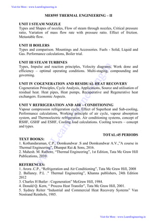
  • 6. V1 and V2 = Inlet and outlet absolute velocity Vr1 and V r2 = Inlet and outlet relative velocity (Velocity relative to the rotor blades.) U = mean blade speed = nozzle angle, = absolute fluid angle at outlet It is to be mentioned that all angles are with respect to the tangential velocity ( in the direction of U ) Velocity diagram of an Impulse Turbine Visit for More : www.LearnEngineering.in Visit for More : www.LearnEngineering.in w w w . L e a r n E n g i n e e r i n g . i n
  • 7. The Single-Stage Impulse Turbine  The single-stage impulse turbine is also called the de Laval turbine after its inventor. The turbine consists of a single rotor to which impulse blades are attached.  Visit for More : www.LearnEngineering.in Visit for More : www.LearnEngineering.in w w w . L e a r n E n g i n e e r i n g . i n
  • 8.  The steam is fed through one or several convergent-divergent nozzles which do not extend completely around the circumference of the rotor, so that only part of the blades is impinged upon by the steam at any one time.  The nozzles also allow governing of the turbine by shutting off one or more them. Compounding in Impulse Turbine If high velocity of steam is allowed to flow through one row of moving blades, it produces a rotor speed of about 30000 rpm which is too high for practical use.   It is essential to incorporate some improvements for practical use and also to achieve high performance.  This is called compounding.   Two types of compounding can be accomplished: (a) velocity compounding and (b) pressure compounding  The Velocity - Compounding of the Impulse Turbine  The velocity-compounded impulse turbine was first proposed to solve the problems of a single-stage impulse turbine for use with high pressure and temperature steam.  It is composed of one stage of nozzles as the single-stage turbine, followed by two rows of moving blades instead of one.  These two rows are separated by one row of fixed blades attached to the turbine stator, which has the function of redirecting the steam leaving the first row of moving blades to the second row of moving blades.    Pressure Compounding or Rateau Staging Visit for More : www.LearnEngineering.in Visit for More : www.LearnEngineering.in w w w . L e a r n E n g i n e e r i n g . i n
  • 9. To alleviate the problem of high blade velocity in the single-stage impulse turbine, the total enthalpy drop through the nozzles of that turbine are simply divided up, essentially in an equal manner, among many single-stage impulse turbines in series,Such a turbine is called a Rateau turbine.  The inlet steam velocities to each stage are essentially equal and due to a reduced Δh. Reaction Turbine  A reaction turbine, therefore, is one that is constructed of rows of fixed and rows of moving blades.  The fixed blades act as nozzles.  The moving blades move as a result of the impulse of steam received (caused by change in momentum) and also as a result of expansion and acceleration of the steam relative to them. The pressure drops will not be equal.  They are greater for the fixed blades and greater for the high-pressure than the low-pressure stages.   The absolute steam velocity changes within each stage as shown and repeats from stage to stage. APPLICATIONS Locomotives Power generations Industrial application for producing steam    Governing of Steam Turbine: The method of maintaining the turbine speed constant irrespective of the load is known as governing of turbines. The device Visit for More : www.LearnEngineering.in Visit for More : www.LearnEngineering.in w w w . L e a r n E n g i n e e r i n g . i n
  • 10. used for governing of turbines is called Governor. There are 3 types of governors in steam turbine, 1.Throttle governing 2.Nozzle governing 3.By-pass governing i.Throttle Governing: Let us consider an instant when the load on the turbine increases, as a result the speed of the turbine decreases. The fly balls of the governor will come down. The fly balls bring down the sleeve. The downward movement of the sleeve will raise the control valve rod. The mouth of the pipe AA will open. Now the oil under pressure will rush from the control valve to right side of piston in the rely cylinder through the pipe AA. This will move the piston and spear towards the left which will open more area of nozzle. As a result steam flow rate into the turbine increases, which in turn brings the speed of the turbine to the normal range. ii)Nozzle Governing: Visit for More : www.LearnEngineering.in Visit for More : www.LearnEngineering.in w w w . L e a r n E n g i n e e r i n g . i n
  • 11. A dynamic arrangement of nozzle control governing is shown in fig. In this nozzles are grouped in 3 to 5 or more groups and each group of nozzle is supplied steam controlled by valves. The arc of admission is limited to 180º or less. The nozzle controlled governing is restricted to the first stage of the turbine, the nozzle area in other stages remaining constant. It is suitable for the simple turbine and for larger units which have an impulse stage followed by an impulse reaction turbine. Solved Problems: 1. A convergent divergent adiabatic steam nozzle is supplied with steam at 10 bar and 250°c.the discharge pressure is 1.2 bar.assuming that the nozzle efficiency is 100% and initial velocity of steam is 50 m/s. find the discharge velocity. Given Data:- Initial pressure(p1)=10bar Initial Temperature(T1)=250°c Exit pressure(p2)=1.2 bar Visit for More : www.LearnEngineering.in Visit for More : www.LearnEngineering.in w w w . L e a r n E n g i n e e r i n g . i n
  • 12. Nozzle efficiency(ηnozzle)=100% Initial velocity of steam (v1)=50m/s To Find:- Discharge velocity (v2) Solution:- From steam table, For 10 bar, 250°c, h1=2943 KJ/kg s1=6.926 KJ/kgk From steam table, For 1.2 bar, hf2 =439.3 KJ/kg ; hfg2=2244.1 KJ/kg; sf2=1.3 61 KJ/kg K ; sfg2=5.937 KJ/kgK. Since s1=s2, S1=sf 2+x2sfg2 6.926=1.361+x2(5.937) X2=0 .9373 We know that, h2=hf2+x2hfg2 = 439.3+(0.9373)2244.1 h2 = 2542KJ/Kg Exit velocity (V2) = Rt[(2000(2943) 2542) + 502] = 896.91m/s. Visit for More : www.LearnEngineering.in Visit for More : www.LearnEngineering.in w w w . L e a r n E n g i n e e r i n g . i n
  • 13. 2. Dry saturated steam at 6.5 bar with negligible velocity expands isentropically in a convergent divergent nozzle to 1.4 bar and dryness fraction 0.956. De termine the final velocity of steam from th e nozzle if 13% heat is loss in friction. Find th e % reduction in the final velocity. Given data: Exit pressure (P2) = 1.4 bar Dryness fract ion (X2) = 0.956 Heat loss = 13% To Find: The percent reduction in final velocity Solution: From steam table for initial pressure P1 = 6.5bar, take values h1 = h1 = 2758.8KJ/Kg Similarly, at 1.4 bar, hfg2 = 2231.9 KJ/Kg hf2 = 458.4KJ/Kg h2 = hf2 + X2 hfg2 = 458.4 + (0.956) 2231.6 h2 = 2592.1 KJ/Kg Final velocit y (V2) = Rt (2000(h1-h2) ) V2 = 577.39 m/s Visit for More : www.LearnEngineering.in Visit for More : www.LearnEngineering.in w w w . L e a r n E n g i n e e r i n g . i n
  • 14. Heat drop is 13%= 0.13 Nozzle efficiency (η) = 1- 0.13 = 0.87 Velocity of s team by considering the nozzle efficiency, y (V2) = Rt (2000(h1-h2) ) x η V2 = 538.55 m/s = % reductio n in final velocity = 6.72% 3.A convergent divergent nozzle receives steam at 7bar and 200o c and it ex pands isentropically into a space of 3bar neglecting the inlet velocity calculat e the exit area required for a mass flow of 0.1Kg/sec . when the flow is in equilibrium through all and super saturated with PV1.3 =C. Given Data: Initiall pressure (P1) = 7bar = 7× 10⁵ N/m2 Initiall temperature (T1) = 200oC Press ure (P2) = 3bar = 3× 10⁵N/m2 Mass flow rate (m) = 0.1Kg/sec PV1.3 =C To Find: Exit area Solution: From st eam table for P1 = 7bar and T1 = 200oC V1 = 0.2999 h1 = 2844.2 Visit for More : www.LearnEngineering.in Visit for More : www.LearnEngineering.in w w w . L e a r n E n g i n e e r i n g . i n
  • 15. S1 = 6.886 Similarly for P2 = 3bar Vf2 = 0.001074 Vg2 = 0.60553 hf2 = 561.5 hfg2 = 2163.2 Sf2 = 1.672 Sfg2 = 5.319 We know that, S1 = S2 = St S1 = Sf2 + X2 Sfg2 6.886 = 1.672 + X2 (5.319) X2 = 0.98 Similarly, h2 = hf2 + X2 hfg2 h2 = 561.5 + 0.98 (2163.2) (i) Flow is in equilibriu m through all: V2=569.56 ν2 = X2 × νg2 = 0.98× 0.60553 = 0.5934 Visit for More : www.LearnEngineering.in Visit for More : www.LearnEngineering.in w w w . L e a r n E n g i n e e r i n g . i n
  • 16. Visit for More : www.LearnEngineering.in Visit for More : www.LearnEngineering.in w w w . L e a r n E n g i n e e r i n g . i n
  • 17. TECHNICAL TERMS 1.Diaphragm - Partitions b etween pressure stages in a turbine's casing. 2. Radial - flow turbine - st eam flows outward from the shaft to the casing. 3. Radial clearance - cleara nce at the tips of the rotor and casing. 4. Axial clearance - the fore -and-aft clearance, at the sides of the rotor and t he casing. 5. balance piston - Instead of piston, seal strips are also used to duplicate a piston's counter force. 6. steam rate - The steam rate is the pounds of steam that must be supplied per kilowatt-hour of generator output at the steam turbine inlet. Visit for More : www.LearnEngineering.in Visit for More : www.LearnEngineering.in w w w . L e a r n E n g i n e e r i n g . i n
  • 18. 7. extraction turbine - ste am is withdrawn from one or more stages, at one or more pressures, for heating, pl ant process, or feedwater heater needs. 8. Wet steam: The steam w hich contains some water particles in superposition. 9. Dry steam / dry saturated steam: When whole mass of steam is converted into steam then it is called as dry steam. 10. Super heated steam: When the dry steam is further heated at consta nt pressure, the temperature increases the above saturation temperature. The steam has obtained is called super heated stea m. 11. Degree of super heat: The difference between the temperature of saturated steam and saturated temperature is c alled degree of superheat. 12. Nozzle:It is a duct of varying cross sectional area in which the velocity increases with the corresponding drop in pressure. 13. Coefficient of nozzle: It is the ratio of actual enthalpy drop to isentropic enthalpy drop. 14. Critical pressure ratio: There is only one value of ratio (P2/P1) which produces maximum discharge fro m the nozzle . then the ratio is called critica l pressure ratio. 15. Degree of reaction: It is defined as the ratio of isentropic heat drop in th e moving blade to isentrpic heat drop in the entire stages of the reaction turbine. 16. Compounding: It is the method of absorbing the jet velocity in stages when the steam flows over moving blades. (i)Velocity compounding (ii)Pressure compounding and (iii) Velocity-pressure compounding 17. Enthalpy: It is the combination of the internal energy and the flow energy. 18. Entropy: It is the function of quantity of heat with respective to the temperature. 19. Convergent nozzle: The crossectional area of the duct decreases from inlet to the outlet side then it is called as convergent nozzle. Visit for More : www.LearnEngineering.in Visit for More : www.LearnEngineering.in w w w . L e a r n E n g i n e e r i n g . i n
  • 19. 20. Divergent nozzle: The crossectional area of the duct increases from inlet to the outlet then it is called as divergent nozzle. Visit for More : www.LearnEngineering.in Visit for More : www.LearnEngineering.in w w w . L e a r n E n g i n e e r i n g . i n
  • 20. SIGNIFICANCE OF STEAM TURBINES Large scale electrical energy production largely depends on the use of turbines. Nearly all of the world's power that is supplied to a major grid is produced by turbines.   From steam turbines used at coal-burning electricity plants to liquid water turbines used at hydro-electric plants, turbines are versatile and can be used in a number of applications.   There are also gas turbines that combust natural gas or diesel fuel for use in remote locations or where a large backup power supply is required. Most power plants use turbines to produce energy by burning coal or natural gas.  The heat produced from combustion is used to heat water in boiler. The liquid water is converted to steam upon heating and is exhausted through a pipe which feeds the steam to the turbine.   The pressurized steam flow imparts energy on the blades and shaft of the turbine causing it to rotate.  The rotational mechanical energy is then converted to electrical energy using a generator. STEAM TURBINES Turbines We shall consider steam as the working fluid Single stage or Multistage Axial or Radial turbines Atmospheric discharge or discharge below atmosphere in condenser Impulse/and Reaction turbine  Impulse Turbines Visit for More : www.LearnEngineering.in Visit for More : www.LearnEngineering.in w w w . L e a r n E n g i n e e r i n g . i n Unit 3
  • 21. Impulse turbines (single-rotor or multirotor) are simple stages of the turbines. Here the impulse blades are attached to the shaft. Impulse blades can be recognized by their shape. The impulse blades are short and have constant cross sections. Schematic diagram of an Impulse Trubine V1 and V2 = Inlet and outlet absolute velocity Vr1 and V r2 = Inlet and outlet relative velocity (Velocity relative to the rotor blades.) U = mean blade speed = nozzle angle, = absolute fluid angle at outlet It is to be mentioned that all angles are with respect to the tangential velocity ( in the direction of U ) Velocity diagram of an Impulse Turbine Visit for More : www.LearnEngineering.in Visit for More : www.LearnEngineering.in w w w . L e a r n E n g i n e e r i n g . i n
  • 22. Visit for More : www.LearnEngineering.in Visit for More : www.LearnEngineering.in w w w . L e a r n E n g i n e e r i n g . i n
  • 23. The Single-Stage Impulse Turbine  The single-stage impulse turbine is also called the de Laval turbine after its inventor. The turbine consists of a single rotor to which impulse blades are attached.   The steam is fed through one or several convergent-divergent nozzles which do not extend completely around the circumference of the rotor, so that only part of the blades is impinged upon by the steam at any one time.  The nozzles also allow governing of the turbine by shutting off one or more them. Compounding in Impulse Turbine If high velocity of steam is allowed to flow through one row of moving blades, it produces a rotor speed of about 30000 rpm which is too high for practical use.   It is essential to incorporate some improvements for practical use and also to achieve high performance.  This is called compounding.   Two types of compounding can be accomplished: (a) velocity compounding and (b) pressure compounding  The Velocity - Compounding of the Impulse Turbine  The velocity-compounded impulse turbine was first proposed to solve the problems of a single-stage impulse turbine for use with high pressure and temperature steam.  It is composed of one stage of nozzles as the single-stage turbine, followed by two rows of moving blades instead of one.  Visit for More : www.LearnEngineering.in Visit for More : www.LearnEngineering.in w w w . L e a r n E n g i n e e r i n g . i n
  • 24. These two rows are separated by one row of fixed blades attached to the turbine stator, which has the function of redirecting the steam leaving the first row of moving blades to the second row of moving blades.    Pressure Compounding or Rateau Staging To alleviate the problem of high blade velocity in the single-stage impulse turbine, the total enthalpy drop through the nozzles of that turbine are simply divided up, essentially in an equal manner, among many single-stage impulse turbines in series,Such a turbine is called a Rateau turbine.  The inlet steam velocities to each stage are essentially equal and due to a reduced Δh. Reaction Turbine  A reaction turbine, therefore, is one that is constructed of rows of fixed and rows of moving blades.  The fixed blades act as nozzles.  The moving blades move as a result of the impulse of steam received (caused by change in momentum) and also as a result of expansion and acceleration of the steam relative to them. The pressure drops will not be equal.  They are greater for the fixed blades and greater for the high-pressure than the low-pressure stages.   The absolute steam velocity changes within each stage as shown and repeats from stage to stage. APPLICATIONS Visit for More : www.LearnEngineering.in Visit for More : www.LearnEngineering.in w w w . L e a r n E n g i n e e r i n g . i n
  • 25. Locomotives Power generations Industrial application for producing steam    Governing of Steam Turbine: The method of maintaining the turbine speed constant irrespective of the load is known as governing of turbines. The device used for governing of turbines is called Governor. There are 3 types of governors in steam turbine, 1.Throttle governing 2.Nozzle governing 3.By-pass governing i.Throttle Governing: Let us consider an instant when the load on the turbine increases, as a result the speed of the turbine decreases. The fly balls of the governor will come down. The fly balls bring down the sleeve. The downward movement of the sleeve will raise the control valve rod. The mouth of the pipe AA will open. Now the oil under pressure will rush from the control valve to right side of piston in the rely cylinder through the pipe AA. This will move the piston and spear towards the left which will open more area of nozzle. As a result steam flow rate into the turbine increases, which in turn brings the speed of the turbine to the normal range. Visit for More : www.LearnEngineering.in Visit for More : www.LearnEngineering.in w w w . L e a r n E n g i n e e r i n g . i n
  • 26. ii)Nozzle Governing: A dynamic arrangement of nozzle control governing is shown in fig. In this nozzles are grouped in 3 to 5 or more groups and each group of nozzle is supplied steam controlled by valves. The arc of admission is limited to 180º or less. The nozzle controlled governing is restricted to the first stage of the turbine, the nozzle area in other stages remaining constant. It is suitable for the simple turbine and for larger units which have an impulse stage followed by an impulse reaction turbine. Visit for More : www.LearnEngineering.in Visit for More : www.LearnEngineering.in w w w . L e a r n E n g i n e e r i n g . i n
  • 27. ME6404 THERMAL ENGINEERING 91 SCE Department of Mechanical Engineering UNIT – 5 REFRIGERATION AND AIR CONDITIONING 5.1 PREREQUISITE DISCUSSION Before 1830, few Americans used ice to refrigerate foods due to a lack of ice- storehouses and iceboxes. As these two things became more widely available, individuals used axes and saws to harvest ice for their storehouses. This method proved to be difficult, dangerous, and certainly did not resemble anything that could be duplicated on a commercial scale. Despite the difficulties of harvesting ice, Frederic Tudor thought that he could capitalize on this new commodity by harvesting ice in New England and shipping it to the Caribbean islands as well as the southern states. In the beginning, Tudor lost thousands of dollars, but eventually turned a profit as he constructed icehouses in Charleston, Virginia and in the Cuban port town of Havana. These icehouses as well as better insulated ships helped reduce ice wastage from 66% to 8%. This efficiency gain influenced Tudor to expand his ice market to other towns with icehouses such as New Orleans and Savannah. This ice market further expanded as harvesting ice became faster and cheaper after one of Tudor’s suppliers, Nathaniel Wyeth, invented a horse-drawn ice cutter in 1825. This invention as well as Tudor’s success inspired others to get involved in the ice trade and the ice industry grew. Ice became a mass-market commodity by the early 1830s with the price of ice dropping from six cents per pound to a half of a cent per pound. In New York City, ice consumption increased from 12,000 tons in 1843 to 100,000 tons in 1856. Boston’s consumption leapt from 6,000 tons to 85,000 tons during that same period. Ice harvesting created a “cooling culture” as majority of people used ice and iceboxes to store their dairy products, fish, meat, and even fruits and vegetables. These early cold storage practices paved the way for many Americans to accept the refrigeration technology that would soon take over the country. CONCEPT 5.2 CONCEPT OF REFRIGERATION Refrigeration is a process in which work is done to move heat from one location to another. The work of heat transport is traditionally driven by mechanical work, but can also be driven by heat, magnetism, electricity, laser, or other means. How does it work? ME6404 THERMAL ENGINEERING 91 SCE Department of Mechanical Engineering UNIT – 5 REFRIGERATION AND AIR CONDITIONING 5.1 PREREQUISITE DISCUSSION Before 1830, few Americans used ice to refrigerate foods due to a lack of ice- storehouses and iceboxes. As these two things became more widely available, individuals used axes and saws to harvest ice for their storehouses. This method proved to be difficult, dangerous, and certainly did not resemble anything that could be duplicated on a commercial scale. Despite the difficulties of harvesting ice, Frederic Tudor thought that he could capitalize on this new commodity by harvesting ice in New England and shipping it to the Caribbean islands as well as the southern states. In the beginning, Tudor lost thousands of dollars, but eventually turned a profit as he constructed icehouses in Charleston, Virginia and in the Cuban port town of Havana. These icehouses as well as better insulated ships helped reduce ice wastage from 66% to 8%. This efficiency gain influenced Tudor to expand his ice market to other towns with icehouses such as New Orleans and Savannah. This ice market further expanded as harvesting ice became faster and cheaper after one of Tudor’s suppliers, Nathaniel Wyeth, invented a horse-drawn ice cutter in 1825. This invention as well as Tudor’s success inspired others to get involved in the ice trade and the ice industry grew. Ice became a mass-market commodity by the early 1830s with the price of ice dropping from six cents per pound to a half of a cent per pound. In New York City, ice consumption increased from 12,000 tons in 1843 to 100,000 tons in 1856. Boston’s consumption leapt from 6,000 tons to 85,000 tons during that same period. Ice harvesting created a “cooling culture” as majority of people used ice and iceboxes to store their dairy products, fish, meat, and even fruits and vegetables. These early cold storage practices paved the way for many Americans to accept the refrigeration technology that would soon take over the country. CONCEPT 5.2 CONCEPT OF REFRIGERATION Refrigeration is a process in which work is done to move heat from one location to another. The work of heat transport is traditionally driven by mechanical work, but can also be driven by heat, magnetism, electricity, laser, or other means. How does it work? ME6404 THERMAL ENGINEERING 91 SCE Department of Mechanical Engineering UNIT – 5 REFRIGERATION AND AIR CONDITIONING 5.1 PREREQUISITE DISCUSSION Before 1830, few Americans used ice to refrigerate foods due to a lack of ice- storehouses and iceboxes. As these two things became more widely available, individuals used axes and saws to harvest ice for their storehouses. This method proved to be difficult, dangerous, and certainly did not resemble anything that could be duplicated on a commercial scale. Despite the difficulties of harvesting ice, Frederic Tudor thought that he could capitalize on this new commodity by harvesting ice in New England and shipping it to the Caribbean islands as well as the southern states. In the beginning, Tudor lost thousands of dollars, but eventually turned a profit as he constructed icehouses in Charleston, Virginia and in the Cuban port town of Havana. These icehouses as well as better insulated ships helped reduce ice wastage from 66% to 8%. This efficiency gain influenced Tudor to expand his ice market to other towns with icehouses such as New Orleans and Savannah. This ice market further expanded as harvesting ice became faster and cheaper after one of Tudor’s suppliers, Nathaniel Wyeth, invented a horse-drawn ice cutter in 1825. This invention as well as Tudor’s success inspired others to get involved in the ice trade and the ice industry grew. Ice became a mass-market commodity by the early 1830s with the price of ice dropping from six cents per pound to a half of a cent per pound. In New York City, ice consumption increased from 12,000 tons in 1843 to 100,000 tons in 1856. Boston’s consumption leapt from 6,000 tons to 85,000 tons during that same period. Ice harvesting created a “cooling culture” as majority of people used ice and iceboxes to store their dairy products, fish, meat, and even fruits and vegetables. These early cold storage practices paved the way for many Americans to accept the refrigeration technology that would soon take over the country. CONCEPT 5.2 CONCEPT OF REFRIGERATION Refrigeration is a process in which work is done to move heat from one location to another. The work of heat transport is traditionally driven by mechanical work, but can also be driven by heat, magnetism, electricity, laser, or other means. How does it work? Visit for More : www.LearnEngineering.in Visit for More : www.LearnEngineering.in w w w . L e a r n E n g i n e e r i n g . i n
  • 28. ME6404 THERMAL ENGINEERING 92 SCE Department of Mechanical Engineering Thermal energy moves from left to right through five loops of heat transfer: 1) Indoor air loop 2) Chilled water loop 3) Refrigerant loop 4) Condenser water loop 5) Cooling water loop 5.3 SIGNIFICANCE Refrigeration has had a large importance on industry, lifestyle, agriculture and settlement patterns. The idea of preserving food dates back to the ancient Roman and Chinese empires. However, refrigeration technology has rapidly evolved in the last century, from ice harvesting to temperature-controlled rail cars. In order to avoid food spoilage, refrigeration plays an important role in day to day life, similarly, Air conditioning is also an important technological system to prevent the human from the hot atmosphere during summer seasons. 5.4 CLASSIFICATION OF REFRIGERATION SYSTEM Types of Refrigeration • Vapour Compression Refrigeration (VCR): uses mechanical energy • Vapour Absorption Refrigeration (VAR): uses thermal energy 5.5 VAPOUR COMPRESSION REFRIGERATION • Highly compressed fluids tend to get colder when allowed to expand • If pressure high enough • Compressed air hotter than source of cooling • Expanded gas cooler than desired cold temperature • Lot of heat can be removed (lot of thermal energy to change liquid to vapour) • Heat transfer rate remains high (temperature of working fluid much lower than what is being cooled) ME6404 THERMAL ENGINEERING 92 SCE Department of Mechanical Engineering Thermal energy moves from left to right through five loops of heat transfer: 1) Indoor air loop 2) Chilled water loop 3) Refrigerant loop 4) Condenser water loop 5) Cooling water loop 5.3 SIGNIFICANCE Refrigeration has had a large importance on industry, lifestyle, agriculture and settlement patterns. The idea of preserving food dates back to the ancient Roman and Chinese empires. However, refrigeration technology has rapidly evolved in the last century, from ice harvesting to temperature-controlled rail cars. In order to avoid food spoilage, refrigeration plays an important role in day to day life, similarly, Air conditioning is also an important technological system to prevent the human from the hot atmosphere during summer seasons. 5.4 CLASSIFICATION OF REFRIGERATION SYSTEM Types of Refrigeration • Vapour Compression Refrigeration (VCR): uses mechanical energy • Vapour Absorption Refrigeration (VAR): uses thermal energy 5.5 VAPOUR COMPRESSION REFRIGERATION • Highly compressed fluids tend to get colder when allowed to expand • If pressure high enough • Compressed air hotter than source of cooling • Expanded gas cooler than desired cold temperature • Lot of heat can be removed (lot of thermal energy to change liquid to vapour) • Heat transfer rate remains high (temperature of working fluid much lower than what is being cooled) ME6404 THERMAL ENGINEERING 92 SCE Department of Mechanical Engineering Thermal energy moves from left to right through five loops of heat transfer: 1) Indoor air loop 2) Chilled water loop 3) Refrigerant loop 4) Condenser water loop 5) Cooling water loop 5.3 SIGNIFICANCE Refrigeration has had a large importance on industry, lifestyle, agriculture and settlement patterns. The idea of preserving food dates back to the ancient Roman and Chinese empires. However, refrigeration technology has rapidly evolved in the last century, from ice harvesting to temperature-controlled rail cars. In order to avoid food spoilage, refrigeration plays an important role in day to day life, similarly, Air conditioning is also an important technological system to prevent the human from the hot atmosphere during summer seasons. 5.4 CLASSIFICATION OF REFRIGERATION SYSTEM Types of Refrigeration • Vapour Compression Refrigeration (VCR): uses mechanical energy • Vapour Absorption Refrigeration (VAR): uses thermal energy 5.5 VAPOUR COMPRESSION REFRIGERATION • Highly compressed fluids tend to get colder when allowed to expand • If pressure high enough • Compressed air hotter than source of cooling • Expanded gas cooler than desired cold temperature • Lot of heat can be removed (lot of thermal energy to change liquid to vapour) • Heat transfer rate remains high (temperature of working fluid much lower than what is being cooled) Visit for More : www.LearnEngineering.in Visit for More : www.LearnEngineering.in w w w . L e a r n E n g i n e e r i n g . i n
  • 29. ME6404 THERMAL ENGINEERING 93 SCE Department of Mechanical Engineering Vapour Compression Refrigeration Cycle Evaporator Low pressure liquid refrigerant in evaporator absorbs heat and changes to a gas Compressor The superheated vapour enters the compressor where its pressure is raised Condenser The high pressure superheated gas is cooled in several stages in the condenser Expansion Liquid passes through expansion device, which reduces its pressure and controls the flow into the evaporator Type of refrigerant • Refrigerant determined by the required cooling temperature • Chlorinated fluorocarbons (CFCs) or freons: R-11, R-12, R-21, R-22 and R-502 Choice of compressor, design of condenser, evaporator determined by • Refrigerant • Required cooling • Load • Ease of maintenance • Physical space requirements • Availability of utilities (water, power) ME6404 THERMAL ENGINEERING 93 SCE Department of Mechanical Engineering Vapour Compression Refrigeration Cycle Evaporator Low pressure liquid refrigerant in evaporator absorbs heat and changes to a gas Compressor The superheated vapour enters the compressor where its pressure is raised Condenser The high pressure superheated gas is cooled in several stages in the condenser Expansion Liquid passes through expansion device, which reduces its pressure and controls the flow into the evaporator Type of refrigerant • Refrigerant determined by the required cooling temperature • Chlorinated fluorocarbons (CFCs) or freons: R-11, R-12, R-21, R-22 and R-502 Choice of compressor, design of condenser, evaporator determined by • Refrigerant • Required cooling • Load • Ease of maintenance • Physical space requirements • Availability of utilities (water, power) ME6404 THERMAL ENGINEERING 93 SCE Department of Mechanical Engineering Vapour Compression Refrigeration Cycle Evaporator Low pressure liquid refrigerant in evaporator absorbs heat and changes to a gas Compressor The superheated vapour enters the compressor where its pressure is raised Condenser The high pressure superheated gas is cooled in several stages in the condenser Expansion Liquid passes through expansion device, which reduces its pressure and controls the flow into the evaporator Type of refrigerant • Refrigerant determined by the required cooling temperature • Chlorinated fluorocarbons (CFCs) or freons: R-11, R-12, R-21, R-22 and R-502 Choice of compressor, design of condenser, evaporator determined by • Refrigerant • Required cooling • Load • Ease of maintenance • Physical space requirements • Availability of utilities (water, power) Visit for More : www.LearnEngineering.in Visit for More : www.LearnEngineering.in w w w . L e a r n E n g i n e e r i n g . i n
  • 30. ME6404 THERMAL ENGINEERING 94 SCE Department of Mechanical Engineering 5.6 Vapour Absorption Refrigeration Evaporator Absorber High pressure generator ME6404 THERMAL ENGINEERING 94 SCE Department of Mechanical Engineering 5.6 Vapour Absorption Refrigeration Evaporator Absorber High pressure generator ME6404 THERMAL ENGINEERING 94 SCE Department of Mechanical Engineering 5.6 Vapour Absorption Refrigeration Evaporator Absorber High pressure generator Visit for More : www.LearnEngineering.in Visit for More : www.LearnEngineering.in w w w . L e a r n E n g i n e e r i n g . i n
  • 31. ME6404 THERMAL ENGINEERING 95 SCE Department of Mechanical Engineering Condenser Evaporative Cooling • Air in contact with water to cool it close to ‘wet bulb temperature’ • Advantage: efficient cooling at low cost • Disadvantage: air is rich in moisture 5.7 COMPARISON BETWEEN VAPOR COMPRESSION AND ABSORPTION SYSTEM 5.8 PERFORMANCE Assessment of Refrigeration • Cooling effect: Tons of Refrigeration 1 TR = 3024 kCal/hr heat rejected • TR is assessed as: TR = Q xCp x (Ti – To) / 3024 ME6404 THERMAL ENGINEERING 95 SCE Department of Mechanical Engineering Condenser Evaporative Cooling • Air in contact with water to cool it close to ‘wet bulb temperature’ • Advantage: efficient cooling at low cost • Disadvantage: air is rich in moisture 5.7 COMPARISON BETWEEN VAPOR COMPRESSION AND ABSORPTION SYSTEM 5.8 PERFORMANCE Assessment of Refrigeration • Cooling effect: Tons of Refrigeration 1 TR = 3024 kCal/hr heat rejected • TR is assessed as: TR = Q xCp x (Ti – To) / 3024 ME6404 THERMAL ENGINEERING 95 SCE Department of Mechanical Engineering Condenser Evaporative Cooling • Air in contact with water to cool it close to ‘wet bulb temperature’ • Advantage: efficient cooling at low cost • Disadvantage: air is rich in moisture 5.7 COMPARISON BETWEEN VAPOR COMPRESSION AND ABSORPTION SYSTEM 5.8 PERFORMANCE Assessment of Refrigeration • Cooling effect: Tons of Refrigeration 1 TR = 3024 kCal/hr heat rejected • TR is assessed as: TR = Q xCp x (Ti – To) / 3024 Visit for More : www.LearnEngineering.in Visit for More : www.LearnEngineering.in w w w . L e a r n E n g i n e e r i n g . i n
  • 32. ME6404 THERMAL ENGINEERING 96 SCE Department of Mechanical Engineering Q = mass flow rate of coolant in kg/hr Cp = is coolant specific heat in kCal /kg °C Ti = inlet, temperature of coolant to evaporator (chiller) in 0°C To = outlet temperature of coolant from evaporator (chiller) in 0°C Specific Power Consumption (kW/TR) • Indicator of refrigeration system’s performance • kW/TR of centralized chilled water system is sum of • Compressor kW/TR • Chilled water pump kW/TR • Condenser water pump kW/TR • Cooling tower fan kW/TR Coefficient of Performance (COP) • The performance of refrigerators and heat pumps is expressed in terms of coefficient of performance (COP), defined as • Measure • Airflow Q (m3/s) at Fan Coil Units (FCU) or Air Handling Units (AHU): anemometer • Air density  (kg/m3) • Dry bulb and wet bulb temperature: psychrometer • Enthalpy (kCal/kg) of inlet air (hin) and outlet air (Hout): psychrometric charts 5.9 APPLICATIONS OF REFRIGERATRION  Metal workers  Oil refineries  Chemical plants  Petrochemical plants  Transporting temperature-sensitive foodstuffs  Dairy products Visit for More : www.LearnEngineering.in Visit for More : www.LearnEngineering.in w w w . L e a r n E n g i n e e r i n g . i n
  • 33. ME6404 THERMAL ENGINEERING 97 SCE Department of Mechanical Engineering AIR CONDITIONERS 5.10 CONCEPT OF AIR CONDITIONING Air conditioning (often referred to as aircon, AC or A/C) is the process of altering the properties of air (primarily temperatureand humidity) to more favourable conditions, typically with the aim of distributing the conditioned air to an occupied space to improve thermal comfort and indoor air quality. 5.11 TYPES OF AIR CONDITIONERS • Room air conditioners • Zoned Systems • Unitary Systems • Window Air-conditioning System • Split Air-conditioning System • Central air conditioning systems 5.11.1 ROOM AIR CONDITIONER • Room air conditioners cool rooms rather than the entire home. • Less expensive to operate than central units • Their efficiency is generally lower than that of central air conditioners. • Can be plugged into any 15- or 20-amp, 115-volt household circuit that is not shared with any other major appliances 5.11.2 ZONED SYSTEMS 5.11.3 CENTRAL AIR CONDITIONING • Circulate cool air through a system of supply and return ducts. Supply ducts and registers (i.e., openings in the walls, floors, or ceilings covered by grills) carry cooled air from the air conditioner to the home. • This cooled air becomes warmer as it circulates through the home; then it flows back to the central air conditioner through return ducts and registers Visit for More : www.LearnEngineering.in Visit for More : www.LearnEngineering.in w w w . L e a r n E n g i n e e r i n g . i n
  • 34. ME6404 THERMAL ENGINEERING 98 SCE Department of Mechanical Engineering 5.11.4 UNITARY SYSTEMS A unitary air conditioning system comprises an outdoor unit including a compressor for compressing a refrigerant, an outdoor heat exchanger for heat exchange of the refrigerant and an expander connected to the outdoor heat exchanger, for expanding the refrigerant; a duct installed inside a zone of a building; a central blower unit having a heat exchanger connected to the outdoor unit through a first refrigerant pipe and a blower for supplying the air heat-exchanged by the heat exchanger to the duct; and an individual blower unit including a heat exchanger connected to the outdoor unit through a second refrigerant pipe and a fan for sending the air heat exchanged by the heat exchanger and disposed in a zone in the building, for individually cooling or heating the zone. Accordingly, cooling or heating operation is performed on each zone of the building, and simultaneously, additional individual heating or cooling operation can be performed on a specific space, so that a cost can be reduced and cooling or heating in the building can be efficiently performed. 5.11.5 WINDOW AIR-CONDITIONING SYSTEM It is the most commonly used air conditioner for single rooms. In this air conditioner all the components, namely the compressor, condenser, expansion valve or coil, evaporator and cooling coil are enclosed in a single box. This unit is fitted in a slot made in the wall of the room, or often a window sill. Windows air conditioners are one of the most widely used types of air conditioners because they are the simplest form of the air conditioning systems. Window air conditioner comprises of the rigid base on which all Visit for More : www.LearnEngineering.in Visit for More : www.LearnEngineering.in w w w . L e a r n E n g i n e e r i n g . i n
  • 35. ME6404 THERMAL ENGINEERING 99 SCE Department of Mechanical Engineering the parts of the window air conditioner are assembled. The base is assembled inside the casing which is fitted into the wall or the window of the room in which the air conditioner is fitted. The whole assembly of the window air conditioner can be divided into two compartments: the room side, which is also the cooling side and the outdoor side from where the heat absorbed by the room air is liberated to the atmosphere. The room side and outdoor side are separated from each other by an insulated partition enclosed inside the window air conditioner assembly. In the front of the window air conditioner on the room side there is beautifully decorated front panel on which the supply and return air grills are fitted (the whole front panel itself is commonly called as front grill). The louvers fitted in the supply air grills are adjustable so as to supply the air in desired direction. There is also one opening in the grill that allows access to the Control panel or operating panel in front of the window air conditioner. TYPES OF CENTRAL AC • split-system • An outdoor metal cabinet contains the condenser and compressor, and an indoor cabinet contains the evaporator • Packaged • The evaporator, condenser, and compressor are all located in one cabinet. 5.11.6 SPLIT AIR-CONDITIONING SYSTEM: The split air conditioner comprises of two parts: the outdoor unit and the indoor unit. The outdoor unit, fitted outside the room, houses components like the compressor, condenser and expansion valve. The indoor unit comprises the evaporator or cooling Visit for More : www.LearnEngineering.in Visit for More : www.LearnEngineering.in w w w . L e a r n E n g i n e e r i n g . i n
  • 36. ME6404 THERMAL ENGINEERING 100 SCE Department of Mechanical Engineering coil and the cooling fan. For this unit you don't have to make any slot in the wall of the room. Further, the present day split units have aesthetic looks and add to the beauty of the room. The split air conditioner can be used to cool one or two rooms. Energy Consumption • Air conditioners are rated by the number of British Thermal Units (Btu) of heat they can remove per hour. Another common rating term for air conditioning size is the "ton," which is 12,000 Btu per hour. • Room air conditioners range from 5,500 Btu per hour to 14,000 Btu per hour. Energy Efficiency • Today's best air conditioners use 30% to 50% less energy than 1970s • Even if your air conditioner is only 10 years old, you may save 20% to 40% of your cooling energy costs by replacing it with a newer, more efficient model Visit for More : www.LearnEngineering.in Visit for More : www.LearnEngineering.in w w w . L e a r n E n g i n e e r i n g . i n
  • 37. ME6404 THERMAL ENGINEERING 101 SCE Department of Mechanical Engineering 5.12 SOLVED PROBLEMS 1. A sling psychrometer gives reading of 250c dry bulb temperature 150c wet bulb temperature. The barometer indicates 760 mm of hg assuming partial pressure of the vapour as 10 mm of Hg. Determine 1. Specific humidity 2. Saturation ratio. Given Data: Dry bulb temperature td =250c Wet bulb temperature tw=150c Barometer pressure pb=760mm of Hg Partial pressure pv= 10mm of Hg To Find: Specific humidity Saturation ratio. Solution: Specific humidity: We know that Specific humidity W = 0.0083 kg/kg of dry air Saturation ratio: From steam table corresponding to dry bulb temperature td =250c We find the partial pressure ps=0.03166 bar = =23.8 mm of Hg ME6404 THERMAL ENGINEERING 101 SCE Department of Mechanical Engineering 5.12 SOLVED PROBLEMS 1. A sling psychrometer gives reading of 250c dry bulb temperature 150c wet bulb temperature. The barometer indicates 760 mm of hg assuming partial pressure of the vapour as 10 mm of Hg. Determine 1. Specific humidity 2. Saturation ratio. Given Data: Dry bulb temperature td =250c Wet bulb temperature tw=150c Barometer pressure pb=760mm of Hg Partial pressure pv= 10mm of Hg To Find: Specific humidity Saturation ratio. Solution: Specific humidity: We know that Specific humidity W = 0.0083 kg/kg of dry air Saturation ratio: From steam table corresponding to dry bulb temperature td =250c We find the partial pressure ps=0.03166 bar = =23.8 mm of Hg ME6404 THERMAL ENGINEERING 101 SCE Department of Mechanical Engineering 5.12 SOLVED PROBLEMS 1. A sling psychrometer gives reading of 250c dry bulb temperature 150c wet bulb temperature. The barometer indicates 760 mm of hg assuming partial pressure of the vapour as 10 mm of Hg. Determine 1. Specific humidity 2. Saturation ratio. Given Data: Dry bulb temperature td =250c Wet bulb temperature tw=150c Barometer pressure pb=760mm of Hg Partial pressure pv= 10mm of Hg To Find: Specific humidity Saturation ratio. Solution: Specific humidity: We know that Specific humidity W = 0.0083 kg/kg of dry air Saturation ratio: From steam table corresponding to dry bulb temperature td =250c We find the partial pressure ps=0.03166 bar = =23.8 mm of Hg Visit for More : www.LearnEngineering.in Visit for More : www.LearnEngineering.in w w w . L e a r n E n g i n e e r i n g . i n
  • 38. ME6404 THERMAL ENGINEERING 102 SCE Department of Mechanical Engineering We know that Saturation ratio. µ= = = 0.41 Result: 1. Specific humidity 0.0083 kg/kg of dry air 2. Saturation ratio. = 0.41 2. A two stages, single acting air compressor compresses air to 20bar. The air enters the L.P cylinder at 1bar and 27oc and leaves it at 4.7bar. the air enters the H.P. cylinder at 4.5bar and 27oc. the size of the L.P cylinder is 400mm diameter and 500mm stroke. The clearance volume In both cylinder is 4% of the respective stroke volume. The compressor runs at 200rpm, taking index of compression and expansion in the two cylinders as 1.3, estimate 1. The indicated power required to run the compressor; and 2. The heat rejected in the intercooler per minute. Given data: Pressure (P4)= 20bar Pressure (P1) = 1bar = 1×10⁵ N/m2 Temperature (T1) = 27oC = 27+273 = 300K Pressure (P2) = 4.7bar Pressure (P3) = 4.5bar Temperature (T3) = 27oC = 27+273 = 300K Diameter (D1) = 400mm 0.4m Stroke (L1) = 500mm = 0.5m N = 200rpm ; n = 1.3 To Find: Indicated power required to run the compressor Solution : ME6404 THERMAL ENGINEERING 102 SCE Department of Mechanical Engineering We know that Saturation ratio. µ= = = 0.41 Result: 1. Specific humidity 0.0083 kg/kg of dry air 2. Saturation ratio. = 0.41 2. A two stages, single acting air compressor compresses air to 20bar. The air enters the L.P cylinder at 1bar and 27oc and leaves it at 4.7bar. the air enters the H.P. cylinder at 4.5bar and 27oc. the size of the L.P cylinder is 400mm diameter and 500mm stroke. The clearance volume In both cylinder is 4% of the respective stroke volume. The compressor runs at 200rpm, taking index of compression and expansion in the two cylinders as 1.3, estimate 1. The indicated power required to run the compressor; and 2. The heat rejected in the intercooler per minute. Given data: Pressure (P4)= 20bar Pressure (P1) = 1bar = 1×10⁵ N/m2 Temperature (T1) = 27oC = 27+273 = 300K Pressure (P2) = 4.7bar Pressure (P3) = 4.5bar Temperature (T3) = 27oC = 27+273 = 300K Diameter (D1) = 400mm 0.4m Stroke (L1) = 500mm = 0.5m N = 200rpm ; n = 1.3 To Find: Indicated power required to run the compressor Solution : ME6404 THERMAL ENGINEERING 102 SCE Department of Mechanical Engineering We know that Saturation ratio. µ= = = 0.41 Result: 1. Specific humidity 0.0083 kg/kg of dry air 2. Saturation ratio. = 0.41 2. A two stages, single acting air compressor compresses air to 20bar. The air enters the L.P cylinder at 1bar and 27oc and leaves it at 4.7bar. the air enters the H.P. cylinder at 4.5bar and 27oc. the size of the L.P cylinder is 400mm diameter and 500mm stroke. The clearance volume In both cylinder is 4% of the respective stroke volume. The compressor runs at 200rpm, taking index of compression and expansion in the two cylinders as 1.3, estimate 1. The indicated power required to run the compressor; and 2. The heat rejected in the intercooler per minute. Given data: Pressure (P4)= 20bar Pressure (P1) = 1bar = 1×10⁵ N/m2 Temperature (T1) = 27oC = 27+273 = 300K Pressure (P2) = 4.7bar Pressure (P3) = 4.5bar Temperature (T3) = 27oC = 27+273 = 300K Diameter (D1) = 400mm 0.4m Stroke (L1) = 500mm = 0.5m N = 200rpm ; n = 1.3 To Find: Indicated power required to run the compressor Solution : Visit for More : www.LearnEngineering.in Visit for More : www.LearnEngineering.in w w w . L e a r n E n g i n e e r i n g . i n
  • 39. ME6404 THERMAL ENGINEERING 103 SCE Department of Mechanical Engineering We know the swept volume of the L.P cylinder = 0.06284 m3 And volumetric efficiency, ηv = 0.9085 or 90.85% Volume of air sucked by air pressure compressor, =1.42 m3/min And volume of air sucked by H.P compressor, We know that indicated work done by L.P compressor = 2123.3×103 J/min = 2123.3 KJ/min And indicated workdone by H.P compressor, ME6404 THERMAL ENGINEERING 103 SCE Department of Mechanical Engineering We know the swept volume of the L.P cylinder = 0.06284 m3 And volumetric efficiency, ηv = 0.9085 or 90.85% Volume of air sucked by air pressure compressor, =1.42 m3/min And volume of air sucked by H.P compressor, We know that indicated work done by L.P compressor = 2123.3×103 J/min = 2123.3 KJ/min And indicated workdone by H.P compressor, ME6404 THERMAL ENGINEERING 103 SCE Department of Mechanical Engineering We know the swept volume of the L.P cylinder = 0.06284 m3 And volumetric efficiency, ηv = 0.9085 or 90.85% Volume of air sucked by air pressure compressor, =1.42 m3/min And volume of air sucked by H.P compressor, We know that indicated work done by L.P compressor = 2123.3×103 J/min = 2123.3 KJ/min And indicated workdone by H.P compressor, Visit for More : www.LearnEngineering.in Visit for More : www.LearnEngineering.in w w w . L e a r n E n g i n e e r i n g . i n
  • 40. ME6404 THERMAL ENGINEERING 104 SCE Department of Mechanical Engineering = 2043.5×103 J/min = 2034.5 KJ/min Total indicated work done by the compressor, W = WL + WH = 2123.3 + 2034.5 = 4157.8 KJ/min Indicated power required to run the compressor = 4157.8 / 60 = 69.3KW 3. In an oil gas turbine installation , air is taken as 1 bar and 30oC . The air is compressed to 4bar and then heated by burning the oil to a temperature of 500oC . If the air flows at the rate of 90Kg/min . Find the power developed by the plant take γ for air as 1.4 Cp as 1KJ/KgK . If 2.4Kg of oil having calorific value of 40,000 KJ/Kg if burned in the combustion chamber per minute. Find the overall efficiency of the plant. Given Data: Pressure (P4 = P3) = 1bar Pressure (P1 = P2) = 4bar Temperature (T2) = 500oC = 500+273 = 773K Mass flow rate of air(ma) = 90Kg/min = 1.5Kg/sec Mass flow rate of fuel (mf) = 2.4Kg/min = 0.04Kg/sec Temperature (T4) = 30oC = 30+273 = 303K γ = 1.4 ; Cp = 1KJ/KgK ; Cv= 40,000 KJ/Kg To Find: Power developed by the plant Performance of the gas turbine Overall efficiency of the plant Solution: ME6404 THERMAL ENGINEERING 104 SCE Department of Mechanical Engineering = 2043.5×103 J/min = 2034.5 KJ/min Total indicated work done by the compressor, W = WL + WH = 2123.3 + 2034.5 = 4157.8 KJ/min Indicated power required to run the compressor = 4157.8 / 60 = 69.3KW 3. In an oil gas turbine installation , air is taken as 1 bar and 30oC . The air is compressed to 4bar and then heated by burning the oil to a temperature of 500oC . If the air flows at the rate of 90Kg/min . Find the power developed by the plant take γ for air as 1.4 Cp as 1KJ/KgK . If 2.4Kg of oil having calorific value of 40,000 KJ/Kg if burned in the combustion chamber per minute. Find the overall efficiency of the plant. Given Data: Pressure (P4 = P3) = 1bar Pressure (P1 = P2) = 4bar Temperature (T2) = 500oC = 500+273 = 773K Mass flow rate of air(ma) = 90Kg/min = 1.5Kg/sec Mass flow rate of fuel (mf) = 2.4Kg/min = 0.04Kg/sec Temperature (T4) = 30oC = 30+273 = 303K γ = 1.4 ; Cp = 1KJ/KgK ; Cv= 40,000 KJ/Kg To Find: Power developed by the plant Performance of the gas turbine Overall efficiency of the plant Solution: ME6404 THERMAL ENGINEERING 104 SCE Department of Mechanical Engineering = 2043.5×103 J/min = 2034.5 KJ/min Total indicated work done by the compressor, W = WL + WH = 2123.3 + 2034.5 = 4157.8 KJ/min Indicated power required to run the compressor = 4157.8 / 60 = 69.3KW 3. In an oil gas turbine installation , air is taken as 1 bar and 30oC . The air is compressed to 4bar and then heated by burning the oil to a temperature of 500oC . If the air flows at the rate of 90Kg/min . Find the power developed by the plant take γ for air as 1.4 Cp as 1KJ/KgK . If 2.4Kg of oil having calorific value of 40,000 KJ/Kg if burned in the combustion chamber per minute. Find the overall efficiency of the plant. Given Data: Pressure (P4 = P3) = 1bar Pressure (P1 = P2) = 4bar Temperature (T2) = 500oC = 500+273 = 773K Mass flow rate of air(ma) = 90Kg/min = 1.5Kg/sec Mass flow rate of fuel (mf) = 2.4Kg/min = 0.04Kg/sec Temperature (T4) = 30oC = 30+273 = 303K γ = 1.4 ; Cp = 1KJ/KgK ; Cv= 40,000 KJ/Kg To Find: Power developed by the plant Performance of the gas turbine Overall efficiency of the plant Solution: Visit for More : www.LearnEngineering.in Visit for More : www.LearnEngineering.in w w w . L e a r n E n g i n e e r i n g . i n
  • 41. ME6404 THERMAL ENGINEERING 105 SCE Department of Mechanical Engineering Power developed by the plant: Let T1,T3 = temperature of air at points 1 and3 Weknow that isentropic expansion 2-3, T3 = T2× 0.673 = 773×0.673 = 520K Similarly for isentropic compression 4-1: T1 = T4/ 0.673 = 303/0.673 = 450K Performance of the gas turbine: We know that work developed by the turbine, = 379.5KJ/s And work developed by the compressor, = 220.5/s Net work or power of the turbine, P = WT - Wc = 379.5 – 220.5 = 159KJ/s = 159KW Overall efficiency of the plant: We know that the heat supplied per second = mf × C = 0.04× 40,000 = 1600 KJ/s Therefore, overall efficiency of the plant, ηo = 159/1600 = 0.099 or 9.99% ME6404 THERMAL ENGINEERING 105 SCE Department of Mechanical Engineering Power developed by the plant: Let T1,T3 = temperature of air at points 1 and3 Weknow that isentropic expansion 2-3, T3 = T2× 0.673 = 773×0.673 = 520K Similarly for isentropic compression 4-1: T1 = T4/ 0.673 = 303/0.673 = 450K Performance of the gas turbine: We know that work developed by the turbine, = 379.5KJ/s And work developed by the compressor, = 220.5/s Net work or power of the turbine, P = WT - Wc = 379.5 – 220.5 = 159KJ/s = 159KW Overall efficiency of the plant: We know that the heat supplied per second = mf × C = 0.04× 40,000 = 1600 KJ/s Therefore, overall efficiency of the plant, ηo = 159/1600 = 0.099 or 9.99% ME6404 THERMAL ENGINEERING 105 SCE Department of Mechanical Engineering Power developed by the plant: Let T1,T3 = temperature of air at points 1 and3 Weknow that isentropic expansion 2-3, T3 = T2× 0.673 = 773×0.673 = 520K Similarly for isentropic compression 4-1: T1 = T4/ 0.673 = 303/0.673 = 450K Performance of the gas turbine: We know that work developed by the turbine, = 379.5KJ/s And work developed by the compressor, = 220.5/s Net work or power of the turbine, P = WT - Wc = 379.5 – 220.5 = 159KJ/s = 159KW Overall efficiency of the plant: We know that the heat supplied per second = mf × C = 0.04× 40,000 = 1600 KJ/s Therefore, overall efficiency of the plant, ηo = 159/1600 = 0.099 or 9.99% Visit for More : www.LearnEngineering.in Visit for More : www.LearnEngineering.in w w w . L e a r n E n g i n e e r i n g . i n
  • 42. 106 5.13 TECHNICAL TERMS BTU - British thermal unit. A unit of heat energy - approximately the amount of energy needed to heat one pound of water by one degree Fahrenheit. dBA – a unit for measuring sound power or pressure, deciBel on the A scale. Capacity – the ability of a heating or cooling system to heat or cool a given amount of space. For heating, this is usually expressed in BTU’s. For cooling, it is usually given in tons. Compressor – the pump that moves the refrigerant from the indoor evaporator to the outdoor condenser and back to the evaporator again. The compressor is often called “the heart of the system” because it circulates the refrigerant through the loop. Condenser – a device used to condense a refrigerant thereby rejecting the heat to another source, typically an air cooled or water cooled condenser. Cassette – a fan coil unit that fits mainly in the ceiling void with only a diffuser plate visible, diffuses conditioned air in one, two, three or four directions. HVAC – heating, ventilation and air conditioning. Inverter system – Constantly alters fan and motor speeds. This enables faster cooling of a room, and the inverter air conditioner doesn’t have to switch itself on and off to maintain a constant temperature. kw – standard measurement of heat or power, 1kw = 1000 watts = 3412Btu/hr = 860kcal. Load Calculation – a mathematical design tool used to determine the heat gain and heat loss in a building so that properly sized air conditioning and heating equipment may be installed. Refrigerant – a substance that produces a refrigerating effect while expanding or vaporizing. Reverse cycle – the reverse cycle air conditioner internally reverses its operation to provide heating or cooling, as required. Split System – a central air conditioner consisting of two or more major components. The system usually consists of a compressor-containing unit and condenser, installed outside the building and a non-compressor – containing air handling unit installed within the building. This is the most common type of system installed in a home. Zoning – the practice of providing independent heating and/or cooling to different areas in a structure. Zoning typically utilizes a system controller, zoning dampers controlled by a thermostat in each zone, and a bypass damper to regulate static pressure in the supply duct. Visit for More : www.LearnEngineering.in Visit for More : www.LearnEngineering.in w w w . L e a r n E n g i n e e r i n g . i n