GeoPulse Pipeliner Detects Buried Pipelines with Sub-Bottom Profiling
•
0 likes•56 views

The GeoPulse Pipeliner uses a towfish with multiple transducers, including a high frequency 14 kHz transducer, to detect buried pipelines. It can be deployed over-the-side from small boats or towed up to 600 meters deep. The system includes a transmitter that outputs pulses between 2-12 kHz or 14 kHz and a receiver to process the returning acoustic signals and record data.

Recommended
Recommended
More Related Content
What's hot
What's hot (20)
Similar to GeoPulse Pipeliner Detects Buried Pipelines with Sub-Bottom Profiling
Similar to GeoPulse Pipeliner Detects Buried Pipelines with Sub-Bottom Profiling (20)
Recently uploaded
Recently uploaded (20)
GeoPulse Pipeliner Detects Buried Pipelines with Sub-Bottom Profiling
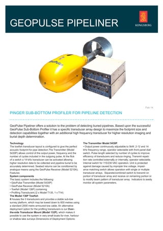
- 1. GeoPulse Pipeliner offers a solution to the problem of detecting buried pipelines. Based upon the successful GeoPulse Sub-Bottom Profiler it has a specific transducer array design to maximize the footprint size and detection capabilities together with an additional high frequency transducer for higher resolution imaging and burial depth determination. PINGER SUB-BOTTOM PROFILER FOR PIPELINE DETECTION GEOPULSE PIPELINER Feb 14 Technology The towfish transducer layout is configured to give the perfect acoustic footprint for pipe detection.The Transmitter (Model 5430P) allows control of the output power, frequency and the number of cycles included in the outgoing pulse. At the flick of a switch a 14 kHz transducer can be activated allowing higher resolution data to be collected and pipeline burial to be accurately determined. Seabed returns can be conditioned by analogue means using the GeoPulse Receiver (Model 5210A). Features System components The basic system includes the following: • GeoPulse Transmitter (Model 5430P) • GeoPulse Receiver (Model 5210A) • Towfish (Model 136P) containing • Profiling Transducers (2 x Model T135, 1 x T14) The Model 136P Towfish It houses the 3 transducers and provides a stable sub-tow survey platform, which may be towed down to 600 metres using a standard 2000 metre armoured tow cable. An alternative deployment option for the profiling transducers is our Over- the-side Transducer Mount (Model 132P), which makes it possible to use the system in very small boats for river, harbour or shallow lake surveys Dimensions of Deployment Options: The Transmitter Model 5430P • Output power continuously adjustable to 5kW. 2-12 and 14 kHz frequency range, operator selectable with front panel dial/ switch. Pulse length selected by number of cycles to improve efficiency of transducers and reduce ringing. Transmit repeti- tion rate controlled externally or internally, operator selectable. Internal switch for 115/230 VAC operation. Unit is protected against damage caused by improper line voltage. Imped- ance matching switch allows operation with single or multiple transducer arrays. Separate/combined switch to transmit on portion of transducer array and receive on remaining portion or to modify beam pattern of transducer array. Indicators to easily monitor all system parameters.
- 2. Receiver Model 5210A Combined TVG and operator controllable gain provide up to 100dB of active gain for low amplitude signal processing. Auto- matic bottom tracking provides constant TVG adjustment re- gardless of bottom variation or degree of slope. (Manual TVG is standard) • AGC provides operator with the ability to manipulate receiver sensitivity for a given reflector intensity. Key program: Multiply and divide-by functions for source triggering flexibility in deep water or extremely shallow water. The tape interface allows for recording of either raw or processed data. Elimin- ates costly interface devices and provides calibration signal for proper recorder adjustment. Optic isolation between receiver and source power supply prevents ground loop interference on acoustic record. TVG record annotation: Upon switch closure by operator or by Nav interface, places a mark on record at every 6dB point throughout TVG ramp. Compensates for spreading and attenuation losses through the water column in deep water. All gain controls, manual or TVG, are in fixed increments en- abling relative reflectivity of different areas to be compared. Signal output to tape recorder is displayed by LED’s signifying maximum possible dynamic range or presence of clipping. Data can be displayed directly onto a wide rangeof industry standard graphic recorders. Dimensions of Deployment Options: • 132P: 70cm (L) x 52cm (W) x 46cm (H), 120kg • Mounting Staff: • One section 183cm, two sections 360cm • 136P: 156cm (L) x 46cm (W) x 46cm (H), 125kg. Transmitter Model 5430P • Output: 5 kW with 0.75% duty cycle, continuously adjustable. 2 to 12kHz, and switchable to 14kHz. • Pulse Cycles: 1, 2, 4, 8, 16 or 32. • Output to Receiver Transformer isolated response flat between approximately 1 kHz and 20 kHz. • Two modes of operation: • A: Flat gain –0dB gain • B: Short range TVG -20dB (10:1) of attenuation during trans- mit pulse and a –20dB to 0dB ramp within 15 ms after end of transmit signal. • Key: External: 2 to 12V pulse or internal: • Power: 115/230 VAC ± 10%, 47 to 63Hz, 220W maximum. • Auxiliary Power: IEC connector, unfused, 6A maximum. • Environmental: Operational: -5 to 50°C, storage: -15 to 85°C • Dimensions: 45.7cm (L) x 43cm (W) x 13cm (H), 18kg Receiver Model 5210A • Amplifier: Differential common mode rejection: 100dB at 60Hz. Sensitivity 30μV RMS input produces 1V RMS output at 90dB total gain with TVG. • Signal to noise: 20dB at 100dB gain 1 kHz centre frequency and 1 kHz bandwidth. • Coarse gain: 40dB maximum. • Fine gain: 0 – 30dB in 3dB increments. • Filter: Low pass and high pass, active type, maximally flat, 24dB/octave minimum roll-off, 0 gain, 0.02 kHz to 15 kHz adjustable in ½ octave increments. • TVG: Dynamic range: 30dB • Rate: approximately flat to 30dB in 14ms. Manual delay: ver- nier adjust from 1 to 14 ms with multiplier of x 1, x 10, x 100 and internal select of x 1000. • AGC: Attack adjustable from 330μs to 330ms. Decay: ad- justable from 330μs to 330ms. Range: 20dB • Power: 115/230VAC ± 10% (internal switch selectable), 47 to 63Hz, 45W maximum. • Environmental: Operational: -5 to 50°C Storage: -15 to 85°C • •imensions: 45.7cm (L) x 43cm (W) x 17.8cm (H), 12kg. Specifications subject to change without any further notice. TECHNICAL SPECIFICATIONS FEATURES • Selectable transmit frequency 2 to 12 kHz • Selectable 14 kHz transducer • Pipeline detection • Over-the-side, towed or hull mounted deployment • Reliable, proven, easy to use • Good penetration and resolution • Combined with side scan sonar • Third party acquisition system integration • Range of tow cables and winches KONGSBERG GEOACOUSTICS LTD Great Yarmouth, UK km.geoacoustics.sales@kongsberg.com +44 1493 600666 www.km.kongsberg.com/geoacoustics OPTIONS