RIGOL Real-time spectrum analyzer RSA5000 Series
•
0 likes•99 views

Real-time spectrum analyzer RSA5000 Series The RSA5065 real-time spectrum analyzer with real-time analysis and sweep analysis, optional vector signal analysis application software (VSA) and EMI measurement application software (EMI), with excellent performance and specifications. Its frequency range is 9kHz to 3.2GHz, and it is available with the tracking source "-TG" model, which can be widely used in enterprise R&D, factory production, education and teaching

Recommended
Recommended
More Related Content
What's hot
What's hot (20)
Similar to RIGOL Real-time spectrum analyzer RSA5000 Series
Similar to RIGOL Real-time spectrum analyzer RSA5000 Series (20)
More from NIHON DENKEI SINGAPORE
More from NIHON DENKEI SINGAPORE (20)
Recently uploaded
Recently uploaded (20)
RIGOL Real-time spectrum analyzer RSA5000 Series
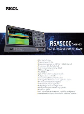
- 1. RSA5000 Ultra-Real technology Frequency: up to 6.5 GHz Displayed average noise level (DANL): <-165 dBm (typical) Phase noise: <-108 dBc/Hz (typical) Level measurement uncertainty: <0.8 dB 6.5 GHz tracking generator Min. RBW 1 Hz Up to 40 MHz real-time analysis bandwidth Multiple measurement modes Various advanced measurement functions Vector signal analysis measurement application (option) EMI measurement application (option) Vector network analyzer application Multiple trigger modes and trigger masks Density, spectrogram, and other display modes PC software options 10.1'' capacitive multi-touch screen, supporting touch gestures USB, LAN, HDMI and other communication and display interfaces Real-time Spectrum Analyzer Series
- 2. 2 RSA5000 Series Real-time Spectrum Analyzer Product Dimensions: Width × Height × Depth = 410 mm × 224 mm × 135 mm The Ultra-Real technology has the following features: Seamless analysis ◎ Seamless I/Q data acquisition in the analysis bandwidth ◎ Gap-free spectrum analysis Based on the Ultra-Real technology, the high-speed real-time measurement mode allows you to acquire the signals in the analysis bandwidth seamlessly and make data analysis. It also provides various display modes, such as Spectrogram, Density, and PVT. Besides, FMT function is also available. Built-in Linux operating system reliable and stable interface 10.1-inch capacitive multi-touch screen supporting touch gestures Support keyboard and mouse operation RF: 9kHz to 3.2/6.5GHz TG : 100kHz to 3.2/6.5GHz -40 to 0dBm Built-in quad-core processor high processing speed
- 3. 3 RSA5000 Series Real-Time Spectrum Analyzer FMT Composite displays Frequency mask trigger (FMT) to trigger the measurement by sporadic or transient events in the spectrum Spectrogram for gap-free display of the spectrum Density spectrum for you to visualize how frequently signals occur Integrates five measurement modes to address the challenges for multiple RF test requirements with one single instrument RSA5000 series provides EMI, RTSA, VSA, and VNA modes in addition to the traditional GPSA mode. Engineers may find it convenient to address multiple RF test challenges with just one instrument, effectively reducing their time and costs, greatly improving their working efficiency. Advanced measurement mode provides test items required for the transmitter test such as multichannel power, ACP, and occupied BW. Quickly recall the limit line compliant with the CISPR standard (e.g. EN55011, EN55012, etc.) to carry out pre-test and monitor the target point with three different detectors.
- 4. 4 With the Density spectrum, you can find out the exceptional signals hidden behind the high-level signals, and capture them accurately with the FMT. In VNA mode, you can make S11, S21, and DTF measurements for the components and circuit networks. The network characteristics of the components under test can be accurately demonstrated in Smith chart, Polar chart, and other formats. You can freely set the way to display the measurement results, demonstrate multiple views of the signals at one time to obtain a clearer display effect through flexible adjustment of the display layout. Various operation modes to improve your operation experience The 10.1-inch capacitive multi-touch screen supports various touch gestures, making it always keep up with the mainstream development trend for screen operation. The gesture-enabled operation such as tapping, dragging, pinching & stretching makes the measurement action smooth and convenient, easy for you to operate the instrument. Meanwhile, the instrument still keeps the knob and key operation as what RIGOL traditional instruments have, optimizing the user-friendly interactive experience to a large extent. It also supports keyboard and mouse operation. Multiple interfaces to improve the connectivity of the instruments The instrument can be connected to a larger display/monitor via the HDMI interface for better display effects. The Web Control function allows you to directly control the device by accessing the device IP address, improving the experience of remote control.
- 5. 5 Specifications Measurement Mode All Measurement Modes Specifications are valid under the following conditions: the instrument is within the calibration period, is stored for at least two hours at 0℃ to 50℃ temperature, and is warmed up for 40 minutes. Unless otherwise noted, the specifications in this manual include the measurement uncertainty. Typical: characteristic performance, which 80 percent of the measurement results will meet at room temperature (approximately 25℃). This data is not warranted and does not include the measurement uncertainty. Nominal: the expected mean or average performance or a designed attribute (such as the 50 Ω connector). This data is not warranted and is measured at room temperature (approximately 25℃). Measured: an attribute measured during the design phase which can be compared to the expected performance, such as the amplitude drift variation with time. This data is not warranted and is measured at room temperature (approximately 25℃). NOTE: All charts in this manual are the measurement results of multiple instruments at room temperature unless otherwise noted. The specifications (except the tracking generator specifications) listed in this manual are those when the tracking generator is off. Frequency RSA5032/-TG/N RSA5065/-TG/N Frequency Range 9 kHz to 3.2 GHz 9 kHz to 6.5 GHz Internal Reference Frequency Reference Frequency 10 MHz Accuracy ±[(time since last calibration × aging rate) + temperature stability + calibration accuracy] Initial Calibration Accuracy Standard <1 ppm Option OCXO-C08 <0.1 ppm Temperature Stability 0℃ to 50℃ , with the reference 25℃ Standard <0.5 ppm Option OCXO-C08 <0.005 ppm Aging Rate Standard <1 ppm/year Option OCXO-C08 <0.03 ppm/year Measurement Mode General-Purpose Spectrum Analyzer (GPSA) Real-time Spectrum Analyzer (RTSA) Vector Signal Analysis Measurement Application (VSA) EMI Measurement Application (EMI) Vector Network Analyzer Application(VNA) Measurement Mode and Product Model Adaptation Table RSA5032 RSA5032-TG RSA5032N RSA5065 RSA5065-TG RSA5065N GPSA √ √ √ √ √ √ RTSA √ √ √ √ √ √ VSA O O O O O O EMI O O O O O O VNA × × √ × × √ Tracking Generator × √ √ × √ √ Note: x indicates not supported; √ indicates standard configuration; O indicates optional configuration. The RSA5000N models include hardware capability not in the RSA5000-TG. The RSA5000-TG models cannot be used in VNA mode.
- 6. 6 GPSA Mode Frequency Frequency Readout Accuracy Marker Frequency Resolution span/(number of sweep points - 1) Marker Frequency Uncertainty ±(marker frequency readout × reference frequency accuracy + 1% × span + 10% × resolution bandwidth + marker frequency resolution) Frequency Counter Resolution 1 Hz Uncertainty ±(marker frequency readout × reference frequency accuracy + counter resolution) Frequency Span Range 0 Hz, 10 Hz to maximum frequency Resolution 2 Hz Uncertainty ±span/(number of sweep points - 1) SSB Phase Noise 20℃ to 30℃,fc = 500 MHz Carrier Offset 1 kHz <-95 dBc/Hz (typical) 10 kHz <-106 dBc/Hz, <-108 dBc/Hz (typical) 100 kHz <-106 dBc/Hz, <-108 dBc/Hz (typical) 1 MHz <-115 dBc/Hz, <-117 dBc/Hz (typical) Note: [1] When the tracking generator is enabled or in zero span mode, the available range of RBW is from 1 kHz to 10 MHz. Measured phase noise @ 10kHz offset of RSA5032/RSA5032-TG/RSA5032N/RSA5065/ RSA5065-TG/RSA5065N Residual FM 20℃ to 30℃ , RBW = VBW = 1 kHz Residual FM <10 Hz (nominal) Bandwidth Set "Sweep Time Rule" to "Accy" Resolution Bandwidth (-3 dB)[1] 1 Hz to 10 MHz, in 1-3-10 sequence RBW Accuracy 3 kHz to 10 MHz, <5% (nominal) 10 Hz to 1 kHz, <15% (nominal) Resolution Filter Shape Factor (60 dB: 3 dB) <5 (nominal) Video Bandwidth (-3 dB) 1 Hz to 10 MHz, in 1-3-10 sequence Resolution Bandwidth (-6 dB) 200 Hz, 9 kHz, 120 kHz, 1 MHz
- 7. 7 Amplitude Measurement Range Range fc ≥ 10 MHz DANL to +30 dBm Maximum Safe Input Level[1] DC Voltage 50 V CW RF Power +30 dBm, attenuation ≥ 40 dB, preamp off. -10 dBm, attenuation = 20 dB, preamp on. Maximum Damage Level CW RF Power +33 dBm (2 W) Note: [1] When fc < 10 MHz, the maximum safe input level is decreased. Displayed Average Noise Level (DANL) RSA5032/-TG/N RSA5065/-TG/N attenuation = 0 dB, sample detector, trace averages ≥ 50, tracking generator off, normalized to 1 Hz, 20℃ to 30℃ , input impedance = 50 Ω. Preamp off 9 kHz to 100 kHz <-120 dBm (typical) <-120 dBm (typical) 100 kHz to 20 MHz <-135 dBm, <-140 dBm (typical) <-135 dBm, <-140 dBm (typical) 20 MHz to 1.5 GHz <-142 dBm, <-145 dBm (typical) <-142 dBm, <-145 dBm (typical) 1.5 GHz to 2.7 GHz <-140 dBm, <-143 dBm (typical) <-140 dBm, <-143 dBm (typical) 2.7 GHz to 3.2 GHz <-138 dBm, <-141 dBm (typical) <-138 dBm, <-141 dBm (typical) 3.2 GHz to 5.5 GHz <-138 dBm, <-143 dBm (typical) 5.5 GHz to 6.5 GHz <-136 dBm, <-141 dBm (typical) Preamp on 100 kHz to 20 MHz <-152 dBm, <-160 dBm (typical) <-152 dBm, <-160 dBm (typical) 20 MHz to 1.5 GHz <-162 dBm, <-165 dBm (typical) <-162 dBm, <-165 dBm (typical) 1.5 GHz to 2.7 GHz <-160 dBm, <-163 dBm (typical) <-160 dBm, <-163 dBm (typical) 2.7 GHz to 3.2 GHz <-158 dBm, <-161 dBm (typical) <-158 dBm, <-161 dBm (typical) 3.2 GHz to 5.5 GHz <-156 dBm, <-161 dBm (typical) 5.5 GHz to 6.5 GHz <-154 dBm, <-159 dBm (typical) Measured frequency VS maximum input power of RSA5032/RSA5032-TG/RSA5032N/RSA5065/RSA5065-TG/RSA5065N Measured frequency VS maximum input power of RSA5032/RSA5032-TG/RSA5032N/RSA5065/RSA5065-TG/RSA5065N
- 8. 8 Measured Displayed Average Noise Level of RSA5032/RSA5032-TG/RSA5032N Measured frequency response of RSA5032/RSA5032-TG/RSA5032N/RSA5065/RSA5065-TG/RSA5065N Measured frequency response of RSA5032/RSA5032-TG/RSA5032N/RSA5065/RSA5065-TG/RSA5065N Level Display Logarithmic Scale 1 dB to 200 dB Linear Scale 0 to reference level Number of Display Points 801 Number of Traces 6 Trace Detector normal, pos-peak, neg-peak, sample, RMS average, voltage average, and quasi-peak Trace Function clear write, max hold, min hold, average, view, blank Scale Unit dBm, dBmV, dBμV, nV, μV, mV, V, nW, μW, mW, W Frequency Response RSA5032/-TG/N RSA5065/-TG/N attenuation = 10 dB, relative to 50 MHz, 20℃ to 30℃ Preamp off 100 kHz to 3.2 GHz <0.5 dB, <0.3 dB (typical) <0.5 dB, <0.3 dB (typical) 3.2 GHz to 6.5 GHz <0.7 dB, <0.5 dB (typical) attenuation = 0 dB, relative to 50 MHz, 20℃ to 30℃ Preamp on 100 kHz to 3.2 GHz <0.7 dB, <0.3 dB (typical) <0.7 dB, <0.3 dB (typical) 3.2 GHz to 6.5 GHz <0.9 dB, <0.5 dB (typical) Measured Displayed Average Noise Level of RSA5065/RSA5065-TG/RSA5065N
- 9. 9 Input Attenuation Switching Uncertainty Setting Range 0 dB to 50 dB, in 1 dB step Switching Uncertainty fc = 50 MHz, relative to 10 dB, preamp off, 20℃ to 30℃ <0.3 dB Absolute Amplitude Accuracy Uncertainty fc = 50 MHz, peak detector, preamp off, attenuation = 10 dB, input signal level = -10 dBm, 20℃ to 30℃ <0.3 dB Reference Level Range Logarithmic Scale -170 dBm to +30 dBm, in 0.01 dB step Linear Scale 707 pV to 7.07 V, 0.11% (0.01 dB) resolution RBW Switching Uncertainty Set "Sweep Time Rule" to "Accy", relative to 30 kHz RBW 1 Hz to 1 MHz <0.1 dB 3 MHz, 10 MHz <0.3 dB Preamp (Option RSA5000-PA) RSA5032/-TG/N RSA5065/-TG/N Frequency Range 100 kHz to 3.2 GHz 100 kHz to 6.5 GHz Gain 20 dB (nominal) Level Measurement Uncertainty 95% confidence level, S/N > 20 dB, RBW = VBW = 1 kHz, preamp off, attenuation = 10 dB, -50 dBm < input level ≤ 0 dBm, fc > 10 MHz, 20℃ to 30℃ Level Measurement Uncertainty <0.8 dB (nominal) Measured level measurement uncertainty VS temperature @-10dBm of RSA5032/RSA5032-TG/RSA5032N/RSA5065/RSA5065-TG/RSA5065N Measured attenuation switching uncertainty of RSA5032/RSA5032-TG/RSA5032N/RSA5065/RSA5065-TG/RSA5065N Measured attenuation switching uncertainty VS temperature of RSA5032/RSA5032-TG/RSA5032N/RSA5065/RSA5065-TG/RSA5065N
- 10. 10 RF Input VSWR RSA5032/-TG/N RSA5065/-TG/N attenuation ≥ 10 dB, preamp off VSWR 300 kHz to 3.2 GHz <1.6 (nominal) <1.6 (nominal) 3.2 GHz to 6.5 GHz <1.8 (nominal) Distortion Second Harmonic Intercept (SHI) fc ≥ 50 MHz, input signal level = -20 dBm, attenuation = 0 dB, preamp off. +45 dBm Third-order Intercept (TOI) fc ≥ 50 MHz, two -20 dBm tones at input mixer spaced by 200 kHz, attenuation = 0 dB, preamp off. +11 dBm, +15 dBm (typical) 1 dB Gain Compression (P1dB)[1] fc ≥ 50 MHz, attenuation = 0 dB, preamp off. 0 dBm (nominal) Note: [1] The frequency interval of the two-tone signals should be greater than 10 MHz. Spurious Response Residual Response input terminated with a 50 Ω load, attenuation = 0 dB, 20℃ to 30℃ <-90 dBm, <-100 dBm (typical) Intermediate Frequency <-60 dBc System-related Sideband referenced to local oscillators, referenced to A/D conversion, referenced to subharmonic of first LO, referenced to harmonic of first LO <-60 dBc Input-related Spurious mixer level = -30 dBm <-60 dBc Measured VSWR of RSA5032/RSA5032-TG/RSA5032N Measured VSWR of RSA5065/RSA5065-TG/RSA5065N of RSA5032/RSA5032-TG/RSA5032N/RSA5065/RSA5065-TG/RSA5065N
- 11. 11 Sweep Sweep Sweep Time span ≥ 10 Hz 1 ms to 4,000 s zero span 1 μs to 6,000 s Sweep Time Uncertainty span ≥ 10 Hz, RBW ≥ 1 kHz 5% (nominal) zero span (sweep time > 1 ms) 5% (nominal) Sweep Mode continue, single Trigger Trigger Trigger Source free run, external 1, external 2, video Trigger Delay span ≥ 10 Hz 0 to 500 ms zero span 0 to 500 ms Tracking Generator Tracking Generator Output RSA5032-TG/N RSA5065-TG/N Frequency Range 100 kHz to 3.2 GHz 100 kHz to 6.5 GHz Output Level Range -40 dBm to 0 dBm Output Level Resolution 1 dB Output Flatness relative to 50 MHz ±3 dB (nominal) @0dBm of RSA5032-TG/RSA5032N/RSA5065-TG/RSA5065N @0dBm of RSA5032-TG/RSA5032N/RSA5065-TG/RSA5065N
- 12. 12 Min. Signal Duration for 100% POI at Different RBWs Duration Time (μs) Span RBW1 RBW2 RBW3 RBW4 RBW5 RBW6 40 MHz 26.9 16.9 11.9 9.32 8.07 7.45 25 MHz 38.9 22.9 14.9 10.9 8.82 7.82 10 MHz 86.8 46.8 26.8 16.8 11.8 9.30 1 MHz 807 407 207 107 56.3 31.3 Amplitude Amplitude Flatness ±0.5 dB[1] (nominal) SFDR <-60 dBc (typical) Density Probability Range 0 to 100% (with a step of 0.1%) Min. Span 5 kHz Persistence Duration 32 ms to 10 s Spectrogram History Depth 8,192 Dynamic Range Covered by Bitmap Color 200 dB PVT Min. Acquisition Time 187.9 μs Max. Acquisition Time 40 s Trigger Trigger Source free run, external 1, external 2, power (time), FMT FMT Trigger Diagram density, spectrogram, normal, PVT Trigger Resolution 0.5 dB (nominal) Trigger Criteria enter, leave, inside, outside, enter-leave, leave-enter Real-time Analysis Bandwidth 25 MHz 40 MHz (Option RSA5000-B40) Min. Signal Duration for 100% POI at the Full-Scale Accuracy maximum span, default Kaiser window 7.45 μs Trace Detector pos-peak, neg-peak, sample, average Number of Traces 6 Window Type Hanning, Blackman-Harris, Rectangular, Flattop, Kaiser, and Gaussian Resolution Bandwidth provides 6 RBWs for each window, except the Rectangular; for Kaiser window Span Min. bandwidth Max. bandwidth 40 MHz 100 kHz 3.21 MHz 25 MHz 62.8 kHz 2.01 MHz 10 MHz 25.1 kHz 804 kHz 1 MHz 2.51 kHz 80.4 kHz 100 kHz 251 Hz 8.04 kHz Max. Sample Rate 51.2 MSa/s FFT Rate 146,484/s (norminal) Number of Markers 8 Amplitude Resolution 0.01 dB Frequency Point 801 Acquisition Time Max. sample rate >156.5 μs RTSA Mode Note: [1] Only applicable to the Normal measurement.
- 13. 13 VSA Mode (Option RSA5000-VSA) Capture Oversampling Capture Oversampling 4, 8, 16 Capture Length Capture Oversampling = 4 Maximum 4096 Capture Oversampling = 8 Maximum 2048 Capture Oversampling = 16 Maximum 1024 Sample Rate Maximum Sample Rate 32 MHz 51.2 MHz (Option RSA5000-B40) Symbol Rate Symbol Rate depends on capture oversampling = sample rate/capture oversampling, ≥1 kHz Usable I/Q Bandwidth Usable I/Q Bandwidth symbol rate × capture oversampling / 1.28 Trigger Mode Trigger Mode free run, external1, external2, power (time), FMT Modulation Format FSK 2FSK, 4FSK, 8FSK, MSK including GMSK, can select differential coding or not PSK BPSK, QPSK, OQPSK, DQPSK, π/4-DQPSK, 8PSK, D8PSK, π/8-D8PSK QAM 16QAM, 32QAM, 64QAM ASK 2ASK, 4ASK Filter Type Measurement Filter Type No Filter, RRC, Gaussian, Rectangular, User Defined Reference Filter Type Raised Cosine, RRC, Gaussian, Rectangular, Half Sine, User Defined Predefined standard Cellular GSM, NADC, WCDMA, PDC, PHP (PHS) Wireless Networking Bluetooth, WLAN (802.11b), ZigBee Others TETRA, DECT, APCO-25 Measurement Uncertainty Specifications apply under the following conditions: temperature from +20 °C to +30 °C signal level ≥ –25 dBm properly adjusted reference level offset between device’ s center frequency and signal’ s center frequency smaller than 5 % of symbol rate Random data sequence Capture oversampling is set to 4. Residual Error for QPSK Test Signal The reference filter is RRC with rolloff factor 0.22. The measurement filter is RRC with rolloff factor 0.22. The result length is 150 symbol. The center frequency is 1 GHz. Residual EVM RMS Symbol Rate 100 kHz < 1.5% (nominal) 1 MHz < 2% (nominal) Residual Error for FSK Test Signal The reference filter is RRC with rolloff factor 0.22. The measurement filter is RRC with rolloff factor 0.22. The FSK reference deviation is a quarter of the symbol rate. The result length is 150 symbols. The center frequency is 1 GHz. Residual Frequency Error RMS Symbol Rate 100 kHz < 2% (nominal) 1 MHz < 2.5% (nominal) EMI Mode (Option RSA5000-EMI) EMI Resolution Bandwidth Resolution Bandwidth (-3 dB) 100 Hz to 10 MHz, in 1-3-10 sequence Resolution Bandwidth (-6 dB) 200 Hz, 9 kHz, 120 kHz, 1 MHz EMI Detector Detector pos-peak, neg-peak, average, quasi-peak, CISPR average, RMS average
- 14. 14 VNA Mode Measurement Setup Frequency Range[1] RSA5032N RSA5065N 100 kHz~3.2 GHz 100 kHz~6.5 GHz Measurement Type Reflection(S11), Transmission(S21), Distance-to-fault (DTF) Measurement Bandwidth 1 kHz~10 MHz(in 1-3-10 sequence) Data Points 101~10001; default 201 Trace Type mem, math, clear write, average, max hold, min hold, Number of Markers 8 Mechanical Calibration Kit Open, Short, Load, Through; User Calibration Kit Transmission Measurement S21 Port Output Power -10 dBm (nom.) Format Lin Mag, Log Mag, Phase, Group Delay Magnitude Range -500 G to 500 G Magnitude Resolution Log: 100f; Lin 1a Dynamic Range S21, RBW=10 kHz, Port1 level=0 dBm, Log Mag, Average=50 80 dB (nom.) Reflection Measurement S11 Port Output Power -10 dBm (nom.) Format Lin Mag, Log Mag, Phase, Group Delay, SWR, Smith Chart (Lin/Phase, Log/Phase, Real/Imag, R+j*X, G+j*B), Polar Chart (Lin/Phase, Log/Phase, Real/Imag) Magnitude Range -500 G to 500 G Magnitude Resolution Log: 100f; Lin 1a VSWR Range -500 G to 500 G Corrected Directivity (With CK106A) S11, Log Mag, Average=50 > 40 dB (nom.) Note: [1] In S11 measurement, the performance becomes worse when the carrier frequency is smaller than 10 MHz. Measured return loss of RSA5000N port 1 Measured return loss of RSA5000N port 1 EMI Key Feature Key Feature CISPR 16-1-1 detectors CISPR 16-1-1 bandwidths log and linear display signal table scan table simultaneous detectors automatic limit testing measure at marker delta to limit step and swept scans report generation
- 15. 15 General Specifications Display Type capacitive multi-touch screen Resolution 1024 × 600 pixels Size 10.1'' Color 24-bit color Printer Supported Protocol network printer Mass Memory Mass Memory Internal Storage 512 MB (nominal) External Storage USB storage device (not supplied) Power Input Voltage Range, AC 100 V to 240 V (nominal) AC Frequency 45 Hz to 440 Hz Power Consumption 55 W (typical), max. 90 W with all options Environment Temperature Operating Temperature Range 0℃ to 50℃ Storage Temperature Range -20℃ to 70℃ Humidity 0℃ to 30℃ ≤ 95% RH 30℃ to 40℃ ≤ 75% RH Altitude Operating Height below 3,048 m (10,000 feet) Electromagnetic Compatibility and Safety EMC complies with EMC Directive 2014/30/EU, complies with or above the standard specified in IEC61326-1:2013/EN61326-1:2013 Group 1 Class A CISPR 11/EN 55011 IEC 61000-4-2:2008/EN 61000-4-2 ±4.0 kV (contact discharge), ±8.0 kV (air discharge) IEC 61000-4-3:2002/EN 61000-4-3 3V/m (80 MHz to 1 GHz); 3V/m (1.4 GHz to 2 GHz); 1V/m (2.0 GHz to 2.7 GHz) IEC 61000-4-4:2004/EN 61000-4-4 1 kV power IEC 61000-4-5:2001/EN 61000-4-5 0.5 kV (phase-to-neutral voltage); 1 kV (phase-to-earth voltage); 1 kV (neutral-to-earth voltage) IEC 61000-4-6:2003/EN 61000-4-6 3 V, 0.15 to 80 MHz IEC 61000-4-11:2004/ EN 61000-4-11 voltage dip: 0% UT during half cycle; 0% UT during 1 cycle; 70% UT during 25 cycles short interruption: 0% UT during 250 cycles Safety complies with IEC 61010-1:2010 (Third Edition)/EN 61010-1:2010, UL 61010-1:2012 R4.16 and CAN/CSA-C22.2 No. 61010-1-12+ GI1+ GI2 Environmental Stress Samples of this product have been type tested in accordance with RIGOL's reliability test regulations and verified to be robust against the environmental stresses of storage, transportation, and end-use; those stresses include, but are not limited to, temperature, humidity, shock, and vibration. The test methods are compliant with standards specified in GB/T6587 Class 2 and MILPRF-28800F Class 3. Distance to Fault(DTF) Port Output Power 0 dBm (nom.) Format Lin Mag, Log Mag, SWR Maximum Distance (meters) 8.0X10¹⁰ x Velocity Factor/Span Fault Resolution in meters 1.5x10⁸ x Velocity Factor/Span Windows Gaussian, Flattop, Rectangular, Hanning, Hamming Velocity Factor 0.1~1
- 16. 16 Input/Output Front Panel Connector RF Input Impedance 50 Ω (nominal) Connector N-type female TG Output Impedance 50 Ω (nominal) Connector N-type female Internal/External Reference Internal Reference Frequency 10 MHz Output Level +3 dBm to +10 dBm, +7 dBm (typical) Impedance 50 Ω (nominal) Connector BNC female External Reference Frequency 10 MHz ± 5 ppm Input Level 0 dBm to +10 dBm Impedance 50 Ω (nominal) Connector BNC female External Trigger Input/Output External Trigger Input 1 Impedance ≥ 1 kΩ (nominal) Connector BNC female Level 5 V TTL level External Trigger Input 2/Trigger Output Impedance on trigger input ≥ 1 kΩ (nominal) on trigger output 50 Ω (nominal) Connector BNC female Level 5 V TTL level IF Output IF Output Frequency 430 MHz ± 20 MHz (nominal) Amplitude RF input power (PRFin) ≤ -10 dBm, attenuation = 0, preamp off. 50MHz, PRFin ± 4 dB (nominal) other frequency, PRFin ± 4 dB + RF frequency response (nominal) Impedance 50 Ω (nominal) Connector SMB male Communication Interface USB Host (4 ports) Connector A plug Protocol version 2.0 USB Device Connector B plug Protocol version 2.0 LAN Connector 100/1000Base, RJ-45 Protocol LXI Core 2011 Device HDMI Connector A plug Protocol HDMI 1.4b Size (W x H x D) 410 mm × 224 mm × 135 mm (16.14'' × 8.82'' × 5.32'') Weight Without Tracking Generator 4.65 kg (10.25 lb) With Tracking Generator 4.95 kg (10.91 lb) Calibration Interval Recommended Calibration Interval 18 months
- 17. 17 Description Order No . Model Real-time Spectrum Analyzer, 9 kHz to 3.2 GHz RSA5032 Real-time Spectrum Analyzer, 9 kHz to 6.5 GHz RSA5065 Real-time Spectrum Analyzer, 9 kHz to 3.2 GHz (include TG) RSA5032-TG Real-time Spectrum Analyzer, 9 kHz to 6.5 GHz (include TG) RSA5065-TG Real-time Spectrum Analyzer, 9 kHz to 3.2 GHz (include TG and VNA) RSA5032N Real-time Spectrum Analyzer, 9 kHz to 6.5 GHz (include TG and VNA) RSA5065N Standard Accessories Quick Guide (hard copy) - Power Cable - Option Vector Signal Analysis Measurement Application RSA5000-VSA EMI Measurement Application RSA5000-EMI Preamplifier (PA) RSA5000-PA High Stability Clock OCXO-C08 Real-time/Analysis Bandwidth 40 MHz RSA5000-B40 Advanced Measurement Kit RSA5000-AMK Spectrum Analyzer PC Software Ultra Spectrum EMI Pre-compliance Test Software S1210 EMI Pre-compliance Software Optional Accessories High-performance Network Analysis Calibration Kit(frequency range: DC to 6.5 GHz) CK106A Economical Network Analysis Calibration Kit(frequency range: DC to 1.5 GHz) CK106E Include: N-SMA cable, BNC-BNC cable, N-BNC adaptor, N-SMA adaptor, 75 Ω-50 Ω adaptor, 900 MHz/1.8 GHz antenna (2pcs), 2.4 GHz antenna (2pcs) DSA Utility Kit Include: N(F)-N(F) adaptor (1pcs), N(M)-N(M) adaptor (1pcs), N(M)-SMA(F) adaptor (2pcs), N(M)-BNC(F) adaptor (2pcs), SMA(F)-SMA(F) adaptor (1pcs), SMA(M)-SMA(M) adaptor (1pcs), BNC T type adaptor (1pcs), 50 Ω SMA load (1pcs), 50 Ω BNC impedance adaptor (1pcs) RF Adaptor Kit Include: 50 Ω to 75 Ω adaptor (2pcs) RF CATV Kit Include: 6 dB attenuator (1pcs), 10 dB attenuator (2pcs) RF Attenuator Kit 30 dB high-power attenuator, with the max power of 100 W ATT03301H N(M)-N(M) RF Cable CB-NM-NM-75-L-12G N(M)-SMA(M) RF Cable CB-NM-SMAM-75-L-12G VSWR Bridge, 1 MHz to 3.2 GHz VB1032 VSWR Bridge, 2 GHz to 8 GHz VB1080 Near-field Probe NFP-3 Rack Mount Kit RM6041 USB Cable CB-USBA-USBB-FF-150 Three years for the mainframe. Warranty Order Information
- 18. DSD07100-2021-05 RIGOL® is the trademark of RIGOL TECHNOLOGIES CO., LTD. Product information in this document subject to update without notice. For the latest information about RIGOL's products, applications and services, please contact local RIGOL Channel Partners or access RIGOL official website: www.rigol.com HEADQUARTER RIGOL TECHNOLOGIES CO., LTD. No.8 Keling Road, New District,Suzhou, JiangSu,P.R.China Tel:+86-400620002 Email:info@rigol.com EUROPE RIGOL TECHNOLOGIES EU GmbH Lindbergh str. 4 82178 Puchheim Germany Tel: +49-89/89418950 Email: info-europe@rigol.com NORTH AMERICA RIGOL TECHNOLOGIES, USA INC. 8140 SW Nimbus Ave. Beaverton, OR 97008 Tel: +1-877-4-RIGOL-1 Fax: +1-877-4-RIGOL-1 Email: info@rigol.com JAPAN RIGOL TECHNOLOGIES JAPAN, LLC MJ Bldg. 3F, 1-7-4 Minato, Chuou-ku, Tokyo, Japan 104-0043 Tel: +81-3-6262-8932 Fax: +81-3-6262-8933 Email: info-japan@rigol.com