TRAFFIC INFORMATION SYSTEM TO DELIVER IN-VEHICLE MESSAGES ON PRE-DEFINED ROUTES USING DSRC BASED V2V COMMUNICATION
•
0 likes•258 views


Recommended
Recommended
More Related Content
What's hot
What's hot (19)
Similar to TRAFFIC INFORMATION SYSTEM TO DELIVER IN-VEHICLE MESSAGES ON PRE-DEFINED ROUTES USING DSRC BASED V2V COMMUNICATION
Similar to TRAFFIC INFORMATION SYSTEM TO DELIVER IN-VEHICLE MESSAGES ON PRE-DEFINED ROUTES USING DSRC BASED V2V COMMUNICATION (20)
TRAFFIC INFORMATION SYSTEM TO DELIVER IN-VEHICLE MESSAGES ON PRE-DEFINED ROUTES USING DSRC BASED V2V COMMUNICATION
- 1. TRAFFIC INFORMATION SYSTEM TO DELIVER IN-VEHICLE MESSAGES ON1 PRE-DEFINED ROUTES USING DSRC BASED V2V COMMUNICATION2 3 4 Attiq Uz Zaman, Corresponding Author5 Graduate Research Assistant6 Department of Electrical Engineering7 University of Minnesota-Duluth,8 271 Marshal –W.-Alworth-Hall, 1023 University Drive,9 Duluth, MN 5581210 Email: zaman013@d.umn.edu11 Tel: 218-213-1575 Fax: 218-726-7267;12 13 M I Hayee14 Professor15 Department of Electrical Engineering16 University of Minnesota-Duluth17 271 Marshal –W.-Alworth-Hall, 1023 University Drive,18 Duluth, MN, 5581219 Email: ihayee@d.umn.edu20 Tel 218 726 674321 22 Navin Katta23 Research and Development Engineer24 Savari Inc.25 Address 2005, De la Cruz Blvd., Suite #131, Santa Clara, CA -9505026 Email: navin@savarinetworks.com27 Tel 408-833-636928 29 Sean Mooney30 Research and Development Engineer31 Savari Inc.32 Address 2005, De La Cruz Blvd., Suite # 131, Santa Clara, CA - 9505033 Email: smooney@savarinetworks.com34 Tel 408-833-636935 36 37 Number of words = (5,471 + 6 figures/tables @ 250) = 6971 Words + 21 References38 Using 7000 words limit + References39 40 41 42 43 Submission Date44 8/01/201545
- 2. A. Zaman, Hayee, Katta and Mooney 2 ABSTRACT1 This paper describes the architecture and functionality of a work zone traffic information system2 using Dedicated Short Range Communication (DSRC) based vehicle to vehicle communication3 and a newly designed hopping algorithm. The proposed hopping algorithm can deliver in-vehicle4 messages transmitted by a roadside unit installed at work zone site to far away vehicles travelling5 towards work zone on pre-defined routes. Our hopping algorithm uses rectangular regions to6 define a hopping route and can hop messages to vehicles on multiple routes at the same time7 without the risk of creating a broadcast storm. Although, the messages hopped by the proposed8 hopping algorithm will generally be applicable to the vehicles on only one side of the road9 (travelling towards work zone), the DSRC equipped vehicles present on both sides of the road will10 participate in hopping to maximize the number of available hopping nodes in situations with lighter11 traffic flow and/or low DSRC market penetration. Furthermore, our hopping algorithm increases12 message security by not requiring any hopping nodes (i.e., DSRC equipped vehicles) to modify13 the contents of the hopped message. We have also performed numerical simulations to evaluate14 the performance of the proposed hopping algorithm. The simulation results show that the proposed15 hopping algorithm works as expected and successfully disseminate DSRC messages along a pre-16 defined route.17 18 19 Keywords: DSRC, V2V Communication, Work Zone, In-Vehicle Message, Hopping, Pre-20 Defined Routes21 22
- 3. A. Zaman, Hayee, Katta and Mooney 3 INTRODUCTION1 One important application of Intelligent Transportation System (ITS) is to improve traffic mobility2 in the area of work zones. Several research articles show that congestion in a work zone can grow3 quickly and often results in accidents, especially in rush hours (1-2). Only in 2013, there were 5794 fatalities due to vehicle crashes in work zones on US roadways (3). Studies have also shown that5 most of the work zone crashes involve rear-ending collision, usually at the end of the traffic queue6 (4) which necessitates the need of an intelligent traffic information system for work zones to7 provide drivers with safety critical information in a timely manner (5,6).8 Any work zone traffic information system has basically dual objectives; (i) gather dynamic9 traffic parameters such as the back of queue location, congestion length and travel time (TT), and10 (ii) disseminate these parameters to the vehicles approaching the congestion in a timely manner11 using Vehicle to Infrastructure (V2I) communication, Vehicle to Vehicle (V2V) communication,12 or a combination of both. Although, any wireless communication technology could be used for13 V2V or V2I communication, Dedicated Short Range Communications (DSRC) has been a14 preferred choice for ITS applications due to its high speed, low latency and highly secure wireless15 communication protocol (7).16 Several research studies have proposed systems and algorithms to accomplish these tasks17 (8 to 17). One critical aspect of these proposed studies is to convey the information message from18 a distance roadside unit or from another vehicle (usually event driven) to a remote vehicle of19 concern. To accomplish this important task, some sort of Vehicular Ad-hoc Networks (VANETs)20 protocol or hopping algorithm is needed. Any successful hopping algorithm for a work zone traffic21 information system needs to have the following three features.22 The traffic parameters should be disseminated to the vehicles on a specific path which23 could potentially be affected by the work zone congestion.24 While broadcasting the message via V2V communication, all vehicles or hopping nodes25 should not broadcast blindly to avoid broadcast storm. (18)26 The risk of any node or vehicle tampering with the messages to be hopped should be27 minimized for security reasons.28 The referenced research studies (8 to 17) if applied to work zone traffic information system29 will have some limitations in terms of not incorporating all of the above mentioned features at the30 same time. In most of these studies (8-14) hopping is performed via a probability based hopping31 algorithm in which each vehicle needs to know the distance from its nearby one-hop neighbors to32 determine if it should hop the message. However, none of these hopping algorithms is able to route33 the message to a specific route. Our earlier proposed method (16, 17) suggests a hopping algorithm34 using DSRC based V2V communication on a predefined route but that method will not be able to35 keep the hopped message on a desired road if sharp turns are present on that route. Additionally,36 that method required each vehicle or hopping node to modify the contents of the header of the37 information message making it prone to security risks.38 In this paper, we propose a work zone traffic information system which solves the problem39 of propagating a message along one or more specific routes regardless of any sharp turns present40 in any of the desired routes. Furthermore, proposed hopping algorithm keeps the message to be41 hopped as “read only” for the vehicles which can potentially increase security as well as decrease42 processing time, because none of the hopping nodes (vehicles) are required to change the contents43 of the original message. This can result in enhanced security because only roadside unit will need44 to use proper security certificates which has more processing power so any desired level of security45 could be achieved at roadside unit.46 We have performed simulations and preliminary field tests to evaluate our proposed47
- 4. A. Zaman, Hayee, Katta and Mooney 4 hopping algorithm using DSRC devices. The results suggest that the proposed hopping algorithm1 can successfully convey an information message from a roadside unit to vehicles on one or more2 specific predefined routes using DSRC based V2V communication. In future, we also plan to do3 more field tests to demonstrate proposed hopping algorithm and traffic information system to carry4 in-vehicle messages via V2V hopping.5 The rest of the paper is organized as follows. An overview of the proposed information6 system architecture is given in next section followed by detailed description of hopping algorithm7 in section 3. The results of simulations and preliminary field tests are described in section 48 followed by conclusions and future work described in the last section.9 10 SYSTEM ARCHITECTURE11 A conceptual diagram of the proposed traffic information system to deliver in-vehicle messages12 on a predefined route is given in Figure 1 in which a work zone is shown on a four-lane highway13 (two lanes in each direction). Due to work zone related lane closure the congestion can build and14 grow past the work zone as shown in Figure 1.15 16 17 FIGURE 1 Conceptual architectural diagram of the developed information system for18 work zone to deliver in-vehicle messages on a predefined route.19 20 In the proposed system, one roadside unit is required and is placed near the end of the work21 zone to disseminate the information message to vehicles on a predefined route. Roadside unit can22 either acquire dynamic traffic parameters for the information message communicating with the23 ongoing DSRC equipped vehicles or it can obtain the information message parameters by a traffic24 control center. The position of the roadside unit is preferred to be at the end of the work zone25 coinciding with the end of the queue which is usually known and fixed. However, the back of the26 queue can vary with the traffic flow, especially in rush hours when it can grow well beyond the27 beginning of the work zone. The traffic information message can contain work zone related28 parameters e.g., lane closure, speed limit, travel time, back of the location etc. In addition to the29 information useful to the driver of the vehicle approaching to the work zone, information message30 will also carry the information about the predefined route for vehicles to determine if the message31 is relevant to a particular vehicle and whether it needs to hop/re-broadcast that message.32 In the proposed algorithm, hopping route can be defined using simple rectangular regions33 as shown in figure 1. Each rectangle is represented by two mid points of shorter sides (longitudes34 and latitudes) and its width. The width of the main rectangles is preferred to be selected at least35 equal to the road width so that the vehicles moving in both directions can participate in hopping.36 In actual practice, we have kept the width to be at least 10 meters more (5 meter on each side) to37 accommodate GPS location error which is around 3-5 m for absolute position error (19). This will38 Roadside Unit Traffic control center Rect 1 Start of Work Zone Back of queue Roadside unit’s wireless range Non-DSRC equipped Vehicles DSRC equipped Vehicles Shorter Rectangles due to curved road Longer Rectangles for straight roads End of work zone Direction of traffic flow
- 5. A. Zaman, Hayee, Katta and Mooney 5 ensure that a vehicle can successfully locate itself inside any rectangle based upon its GPS1 coordinates. The maximum rectangle width should be restricted to exclude as many parallel roads2 as possible or significant portions of crossing roads to avoid dissemination of the information3 message to the vehicles on unwanted routes. Each DSRC equipped vehicle’s On-Board Unit4 (OBU) contains a GPS receiver in addition to DSRC radio and a processing unit. The concatenated5 set of rectangles inside the information message, represents a complete hopping route. The number6 of concatenated rectangles in a given hopping route can vary depending upon the curvature of the7 road with shorter rectangles for the curved part of the road and longer rectangles for the straight8 part of the road as shown in Figure 1. Adjacent concatenated rectangles in a given hopping route9 may slightly overlap each other for the curved part of the road (Figure 1). The rectangular regions10 or rectangles constituting the hopping route can be drawn for any desired hopping route using a11 web based application which is also being developed as part of our ongoing SBIR project and will12 be described in a future work. Each hopping route in the form coordinates of concatenated13 rectangles is encoded in the header of the information message by the roadside unit before14 transmitting.15 Information messages can be disseminated to more than one geographical routes at the16 same time as long as all hopping routes are encoded in the header of the information message by17 the roadside unit. Two such scenarios of multiple hopping routes are shown in Figure 2. First18 scenario represents a highway merge junction where two highways merge to a single highway19 having a work zone. The work zone related information messages will be applicable to both of20 these highways because vehicles coming on both these highways towards work zone direction will21 end up passing through the work zone. Therefore, there is a need to disseminate the message to the22 vehicles on both highway routes. Similarly, the second scenario of Figure 2 represents a T-junction23 intersection where there is a work zone on one leg of the T-junction. In case of multiple hopping24 routes, each geographic route will be defined using a web based application and encoded in the25 header of the information message, separately, by the roadside unit. Following the rectangle which26 covers the highway merge junction or split of the hopping route, as shown in Figure 2 where there27 are two distinct routes in each of the two scenarios represented by rectangles (1, 2, and 3a) and (1,28 2, and 3b).29 As mentioned earlier, traffic information message can either be dynamically acquired by30 the roadside unit or it can be sent from a remote traffic information center. In this paper, for the31 demonstration of hopping algorithm, we will assume that the traffic information message is being32 provided to the roadside unit by a traffic control center. However, in our future field trials we will33 use a dynamic traffic parameter acquisition algorithm which we have recently developed under34 this project (to be described in a future work).35
- 6. A. Zaman, Hayee, Katta and Mooney 6 1 FIGURE 2 Two scenarios depicting the need of multiple predefined hopping routes.2 3 Once a roadside unit is installed and provided with the information message as well as the4 hopping route, it prepares the information message for hopping by encoding the hopping route in5 the header of the information message. For this paper, we are assuming that information message6 is in the form of DSRC based Traveler Information Message (TIM). The optional data fields of the7 TIM are used to carry the hopping route information. We are also developing a web based TIM8 configuration tool to accomplish this task which will be described in a future work. The roadside9 unit will periodically transmit TIM which will be received by all the DSRC equipped vehicles’10 OBUs present on the road within the direct wireless access range of the roadside unit. After11 receiving TIM from roadside unit, each vehicle first determines if it is on the desired route defined12 in the TIM as well as it will compare its calculated direction of travel with the direction given in13 the TIM to determine if the TIM is applicable to the vehicle. If so, the vehicle’s OBU will extract14 relevant information from the TIM and present that information to the driver via an android based15 audio-visual interface which is also under development. However, even if the information message16 is not applicable to the vehicle because it is travelling in the direction opposite to the work zone17 congestion but still present on the hopping route, it will participate in hopping by using our18 proposed hopping algorithm to determine if it should hop or rebroadcast the received TIM for the19 RSE Rect 1 Rect 2 Junction region Highway 3 Highway 2 (i) RSE T junction with or without a stop sign Rect 1 Rect 2 Rect 3a Rect 3b (ii)
- 7. A. Zaman, Hayee, Katta and Mooney 7 vehicles farther away on the hopping route. We will describe the hopping algorithm in more detail1 in the following section.2 3 HOPPING ALGORITHM4 Our proposed hopping algorithm works in such a way that any vehicle which will hop the message5 will not be required to make any changes in the original message before re-broadcasting that6 message. This will have an additional benefit that less processing power will be used at each7 hopping node (or DSRC equipped vehicle) as well as is less vulnerable to security risk by rogue8 elements which could distort the contents of the original information message before broadcasting.9 Furthermore, our hopping algorithm confines the message broadcast to a predefined hopping route10 to ensure that only those vehicles receive the message which need the relevant information. Finally,11 our algorithm will avoid broadcast storm (18) by ensuring that if more than one vehicle receives12 an information message at the same time, only one of those vehicles rebroadcasts it. If multiple13 vehicles compete to hop the message, our hop timing control procedure will resolve the contention,14 making sure only one of those vehicles rebroadcasts the message. Next, we will describe following15 three key features of our hopping algorithm to explain the functionality of our algorithm.16 1) Predefined hopping route17 2) Hop timing control18 3) DSRC specific hop timing control limitation and solution19 20 Predefined Hopping Route21 As explained earlier, each hopping route consists of concatenated rectangular regions on a desired22 road. Each rectangle is represented by longitude and latitude of mid points of two shorter sides23 and its width which is selected as equal to the width of the road (considering both sides) plus an24 additional 10 m or so to accommodate GPS location error whereas length of each main rectangle25 is preferred to be kept as long as possible without skipping any curved path or adding too many26 unintended parallel routes, so that less rectangles are required to define a specific route in the27 header of information message, which will result in smaller information packet size to transmit28 through the air. A hypothetical hopping route with corresponding rectangular regions is shown in29 Figure 3. The hopping route shown in Figure 3 consists of only 4 main rectangles marked from M30 = 1 to 4. The roadside unit will need to encode the coordinates of each of these 4 concatenated31 rectangles in the header of the information message e.g., TIM to be hopped to that particular route.32 Length of each main rectangle is assumed to be much larger than the wireless access range of33 DSRC which means that generally more than one hop is needed in each main rectangle to carry34 the information message through the rectangle. Therefore, when each vehicle or OBU receives an35 information message to be hopped, it virtually divides each main rectangle into several sub-36 rectangles shown for main rectangle M = 2 in Figure 3(a) which are numbered from N = 1 to NM.37 The rationale of dividing each main rectangle into virtual sub-rectangles will be discussed in the38 next section of hop timing control. The length of each virtual sub-rectangle is determined by the39 OBU in such a way that the distance from the beginning of any sub-rectangle to the end of the40 following adjacent sub-rectangle does not exceed the practical wireless access range of DSRC.41 Although, theoretical range of DSRC is 1 km (20), in most practical scenarios it turns out to be42 around 500 m so our algorithm will keep the maximum length of each sub-rectangle to be no more43 than 250 m. The minimum vehicle density required to successfully propagate TIM through the44 hopping route will be at least one vehicle per 500 m covering at least 2 sub-rectangles or more45 depending upon the calculated length of the sub- rectangles. Equations to calculate sub-rectangle46 length are given in next section.47
- 8. A. Zaman, Hayee, Katta and Mooney 8 1 2 FIGURE 3 A typical hopping route with 4 main rectangles showing sub-rectangles of one3 main rectangle with (a) an OBU in second main rectangle, and (b) multiple OBUs in first4 main rectangle to illustrate message hopping. Note that in (b), the hopping route is shown5 with solid arrows and dashed arrows (only shown in first three sub-rectangles) indicate6 message was received but not hopped.7 8 Hop Timing Control9 Hop timing control mechanism is designed to avoid broadcast storm and minimize the number of10 total hops to carry out the information message to the farthest end of the hopping route by ensuring11 that only farthest vehicle or OBU in any sub-rectangle hops the received information message.12 Once a vehicle or OBU receives an information message from roadside unit or a preceding vehicle,13 it will determine which main rectangle it falls in using a simple geometrical calculation method14 (not given in this paper). If the vehicle or OBU is not present in any of the main rectangles, then it15 means that the information message was not meant for this vehicle and the vehicle just ignores the16 information message. However, if an OBU can locate itself on one of the main rectangles and17 determines the number of main rectangle (M) it falls in, then it will calculate the perpendicular18 distance from its current position to the beginning of the main rectangle (DM) as shown in Figure19 3a. Based upon DM and length of the main rectangle (LM), each OBU will divide the main rectangle20 into virtual sub-rectangles and determine the total number of sub-rectangles (NM) in the main21 rectangle M, as well as the number N of the sub-rectangle it falls in using equations 1 to 3.22 23 250 M M L ceil=N (1)24 25 26 M M SRM N L =L (2)27 28 N = 1 N = 2 N = 3 N = 4 - - - - - - - - - - - - - - - - - - - - - - - - - - N = Nm LSRM 0.1-0.2 0.2-0.3 N = 1 N = 2 N = 3 N = 7 N = 8 N = 9N = 4 N = 5 N = 6 N = 10 g 0.3-0.4 0.4-0.5 0.5-0.6 0.6-0.7 0.7-0.8 0.8-0.9 0.9-1.0 1.0-1.1 i h jf d eca b k l m nRSU Hopping windows (sec) (a) (b)
- 9. A. Zaman, Hayee, Katta and Mooney 9 SRM M L D ceil=N (3)1 2 Where NM is number of sub-rectangle in a given rectangle, LM is the length of that given3 main rectangle calculated as the straight line distance between the two mid points of the main4 rectangle given in the hopping route, LSRM is the length of each sub-rectangle in Mth main rectangle,5 N is the number of the sub-rectangle in which the vehicle’s OBU is located, and DM is the6 perpendicular distance from the position of the vehicle to the beginning of the region.7 The rationale of dividing each main rectangle in multiple sub-rectangles is to assign a8 timing window defined by lower time limit (LTL) and upper time limit (UTL) to each sub-rectangle9 in such a way that any vehicle or OBU will only be able to hop the message within its own timing10 window to avoid broadcast storm. However, for any OBU to hop the message, it must receive the11 message before the LTL of its timing window. For illustrative purposes, we have assigned a 10012 msec timing window to each sub-rectangle so that any information message can be hopped through13 one sub-rectangle in 100 msec as shown in Figure 3b. This timing window can be varied for various14 applications, however, for DSRC applications, it seems to be a natural choice because one15 complete cycle of DSRC service and control channel is 100 msec (21).16 Once an OBU determines N and NM using equation 1 to 3 above, it will now calculate its17 sub-rectangle’s LTL using equation 4.18 19 ))(1.0())1.0)(((__ 1 1 NiN=LimitTimeLower M i M (4)20 21 After calculating LTL of the sub-rectangle N, the OBU will calculate a hopping wait time22 (HWT) using equation 5 to determine when it will actually rebroadcast the message.23 24 )1.0( 250 250)1(( 1.0 ND LTL=HWT M (5)25 After calculating HWT, an OBU will wait for (HWT – Normalized Current Time) before26 actually rebroadcasting the message, where the Normalized Current Time is the time difference27 between the time when the information message or TIM was received by an OBU and the time28 when it was transmitted first by the roadside unit. It should be noted that first transmission time is29 also encoded by the roadside unit in the header of the information message i.e., TIM in this case.30 HWT is calculated in such a way that the OBUs near the beginning of the sub-rectangle31 have higher HWT values as compared to those OBUs which are farther away from the beginning32 of the sub-rectangle. As a result, if multiple OBUs are located inside one sub-rectangle and receive33 the same TIM at the same time, then the OBU farthest from the beginning of that sub-rectangle34 will re-broadcast the message first. When the other OBUs in the same sub-rectangle which are still35 waiting to hop, receive the same message again, they will come out of their waiting mode and will36 not hop. The OBUs will recognize if the two messages are the same by comparing one of the37 unique message field which in the case of TIM was its transmission time.38 To illustrate the hopping algorithm’s functionality, Figure 3b shows multiple OBUs in a39 given main rectangle (M = 1) along with virtual sub-rectangles and their corresponding hopping40 windows. For the illustrative purposes, we have assumed that the number of sub-rectangles (NM)41 in this main rectangle is 10 and length of each sub-rectangle is around 250 m which is maximum42 possible length. Once an information message or TIM is transmitted by the roadside unit, assume43
- 10. A. Zaman, Hayee, Katta and Mooney 10 that it is received by OBUs “a” and “b” in the first sub-rectangle (N = 1) at almost the same time1 because both are within the wireless access range of roadside unit. Both OBUs will wait for a2 specific time (HWT – Normalized Current Time) before rebroadcasting. Due to it being farther3 away, OBU “b” will have a smaller HWT as compared to HWT of OBU “a”. Therefore, OBU “b”4 will hop the TIM first. Now the TIM hopped by OBU “b” will be received by all OBUs that are5 within the wireless access range of OBU “b” (OBU “a”, “c” and “d”). Since OBU “a”, which is6 waiting to hop that message, will receive the same TIM for the second time inside its hopping7 window (0.1-0.2 s), it will recognize that this TIM has already been hopped by an OBU which is8 in the same sub-rectangle and thus it will terminate its waiting process and will not hop. On the9 other hand OBUs “c” and “d” will start waiting to hop this TIM according to their respective10 calculated HWTs. Since HWT of OBU “c” will be smaller than that of OBU “d”, it will hop TIM11 first. This process continues until the message reaches to OBU ‘n’ (Figure 3b). Please note that the12 solid arrows in Figure 3b represent the actual hopping paths while the dashed arrows (shown only13 in first two sub-rectangles) represent the TIM reception paths which do not end up hopping the14 message.15 16 DSRC Specific Hop Timing Control Limitation and Solution17 If messages are transmitted according to any non-DSRC based protocol then the above mentioned18 equations would work fine but according to DSRC based protocol, every 100 msec is divided into19 50 msec of “control window” and 50 msec of “service window” (21). TIM can be20 transmitted/received only inside the service time window by a DSRC device. Therefore equation21 4 and 5 are modified to make sure that OBUs only transmit during the “service window”. The22 modified equations 4 and 5 are given below as equations 6 and 7.23 24 05.0))(1.0())1.0)(((__ 1 1 NiN=LimitTimeLower M i M (6)25 26 )049.0( 250 250)1(( 049.0 ND LTL=HWT M (7)27 28 To illustrate the difference between using a full 100 msec window as compared to using29 only service window (50 msec) for hopping, a graphical timeline is shown in Figure 4 for first 430 sub-rectangles with OBUs ‘a’to ‘d’of Figure 3b. This comparative timeline explains the difference31 between the calculated HWTs using original and modified equations.32 The hopping windows are shrunk from 100 msec to 50 msec when we use only service33 time window as seen in Figure 4. Initially both OBUs “a” and “b” receive information message or34 TIM but OBU “b” will hop the message first because its HWT will be less than the HWT of OBU35 “a”. To illustrate the difference in calculated HWTs in both cases, let’s assume that the HWT for36 OBU “b” is around 125 msec using the full 100 msec hopping window. Since that hopping time37 will occur in the middle of the control window (100-150 msec.), so OBU ‘b’ cannot hop the TIM38 until control window expires at 150 msec timing mark and service time window starts. However,39 by using our modified equations (6) and (7), the HWT of OBU “a” turns out to be 165 msec which40 will enable the OBU “b” to rebroadcast within its “service window”. Similarly HWTs of OBU “c”41 and “d” will be changed so that they always fall in “service window”.42
- 11. A. Zaman, Hayee, Katta and Mooney 11 1 2 Figure 4 Hopping timeline depicting the difference between using a full 100 msec timing3 window and half of 100 msec window as in the case of DSRC where only 50 msec service4 window is available for transmission. 4 OBUs (a to d) are shown in four sub-rectangles of5 250 m each.6 7 SIMULATIONS AND PRELIMINARY FIELD TESTS8 For evaluation purposes we performed simulations in the lab and conducted preliminary field tests9 to assess our proposed hopping algorithm. To perform the simulations, we chose the West10 Arrowhead Road in Duluth, MN where we also performed our preliminary field test as shown in11 Figure 5. The total road length in consideration is 2.5 km which is defined by two main rectangles12 of lengths 1 and 1.5 km to represent the hopping route. The width of that specific portion of the13 road at its widest point is about 21 m. Therefore, we selected the rectangle width to be14 52 m (2×21+10).15 The message is hopped from one end (left side in Figure 5) to the other end on this16 predefined route using our hopping algorithm. To test our hopping algorithm timing, we have17 purposely selected 11 potential locations on 2.5 km section of the road where hopping nodes or18 OBUs could be present to conduct the hopping in such a way that at least there is one OBU in each19 sub-rectangle. Furthermore, we also included one OBU potential location which is outside of the20 main rectangles or the hopping route to demonstrate that it will not participate in hopping using21 our algorithm. We obtained the actual longitude and latitude of all these 12 locations from Google22 Maps and provided these as input to our hopping algorithm to calculate HWT, and to evaluate23 which OBUs will hop the message.24 The message is hopped from one end (left side in Figure 5) to the other end using proposed25 hopping algorithm. To test hopping algorithm timing, we have purposely selected 11 potential26 locations on 2.5 km section of the road where hopping nodes or OBUs could be present to conduct27 the hopping in such a way that at least there is one OBU in each sub-rectangle. Furthermore, we28 also included one OBU potential location which is outside of the main rectangles or the hopping29 route to demonstrate that it will not participate in hopping using our algorithm. We obtained the30 actual longitude and latitude of all these 12 locations from Google Maps and provided these as31 Time (ms) Dist (m) Time (ms) a c db 250 m 750 m500 m 200 ms 400 ms300 ms 200 ms 400 ms300 ms Waiting time for c before hopping Waiting time for d before hopping 150 ms 250 ms 350 ms Waiting time for c before hopping Waiting time for d before hopping Full window available Only service window available Control window Control window Control window b hops d hopsc hops LTL LTL DRSC equipped vehicle OBU’s hopping time using full window OBU’s hopping time using service window OBU’s projected hopping time but does not hop OBU’s projected hopping time but does not hop in service window 100 ms 100 ms 0 m a does not hop
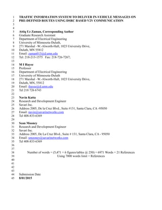
- 12. A. Zaman, Hayee, Katta and Mooney 12 input to our hopping algorithm to calculate HWT, and to evaluate which OBUs will hop the1 message.2 3 FIGURE 5 (a) Section of West Arrowhead Rd showing hopping route defined by two main4 rectangles, and the location of 12 OBUs used for the simulations to demonstrate hopping5 algorithm. (b) Section of West Arrowhead Rd used for preliminary road tests.6 7 For simulation purposes, roadside unit is assumed to be at the far left edge of the first main8 rectangle and transmits TIM at time 0.00 seconds. Also the direct wireless access range of each9 OBU and the roadside unit is assumed to be 300 m so that the maximum sub-rectangle length10 calculated by each OBU will be 250 m. The hopping algorithm code was written in C and run on11 Savari OBU S103 which runs a Linux based Operating System. At each OBU location, calculated12 parameters were logged and shown in Table 1.13 The simulation results in Table 1 show that the OBUs in each sub-rectangle hop TIM in14 accordance to hopping windows and expected HWT (4th and 5th columns of Table 1). There are15 two important points to be noted here which are highlighted in the table and discussed below.16 In 6th sub-rectangle (2nd sub-rectangle of main rectangle 2), there are 2 vehicles (OBUs #17 6 and 7). Both received TIM messages at almost the same time. After receiving TIM18 message both vehicles will calculate their respective HWT times. However, HWT of the19 OBU #7 is smaller than that of OBU #6, therefore, it will hop the TIM first and upon20 receiving the same TIM again within this hopping window, OBU #6 will stop its hopping21 process.22 OBU #8 is outside of both main-rectangles but is still in the wireless access range of its23 neighboring OBUs on the hopping route. Therefore, it receives a TIM at 954 msec but it24 will drop the TIM because it fails to determine which main rectangle it falls in. This25 ensures that our hopping algorithm will confine the propagation of TIM to the vehicles on26 a predefined hopping route.27 OBU 6 OBU 7 OBU 8 OBU 6 OBU 7 N = 1 N = 2 N = 3 N = 3 N = 4 N = 5N = 4 N = 1 N = 2 N = 6 OBU 1 OBU 2 OBU 3 OBU 4 OBU 5 OBU 9 OBU 10 OBU 12OBU 11 RSU OBU 2 OBU 3OBU 1 PCMS https://maps.google.com/(a) (b)
- 13. A. Zaman, Hayee, Katta and Mooney 13 TABLE 1 Simulation Results1 2 In preliminary field tests we successfully demonstrated hopping of a message across a 1.23 km section of West Arrowhead Road. We placed an RSU on one end and a Portable Changeable4 Message Sign (PCMS) on the other end of this road section with three OBUs between the RSU5 and the PCMS as shown in Figure 5b. In our preliminary tests, the RSU was programmed to6 transmit TIM every one second. The three OBUs helped hopped the message to the PCMS which7 displayed a message when hopped TIM was received successfully and displayed a different8 message when hopped TIM was not received. We changed the spacing of three OBUs between the9 RSU and PCMS to evaluate the range of RSU and OBUs for successful hopping. The range of10 RSU was more than 500m while range of all OBUs was around 250 m. The hopping algorithm11 worked as desired regardless of the positions of the OBUs as long as the maximum spacing12 between any two was not more than the DSRC range.13 14 CONCLUSIONS AND FUTURE WORK:15 We have developed a hopping algorithm for a work zone traffic information system to deliver in-16 vehicle messages using DSRC based V2V communication. The developed hopping algorithm can17 disseminate information messages on one or more pre-defined routes consisting of any kind of18 highways or roads including merge and T-junctions. The proposed algorithm uses vehicles moving19 in both directions on a particular route for hopping and minimizes the number of hops to carry the20 message and avoids the broadcast storm at the same time. Our simulation and preliminary field21 test results show that the proposed algorithm works as intended by successfully avoiding broadcast22 storm and keeping the information message on the desired hopping route. We are also developing23 a web based TIM configuration tool for roadside units and an ANDROID based audio-visual24 interface for OBU to deliver traffic information message contents to the drivers. These components25 of our full system will be described in a future work after we perform the final field tests to26 demonstrate our hopping algorithm.27 OBU No. Distance from roadside unit (m) LTL-UTL (msec) TIME at which TIM is received (msec) TIME at which TIM is supposed to hop (msec) TIM hopped? (Yes/No) 1 240 150-199 0.0 152 Yes 2 490 250-299 152 251 Yes 3 725 350-399 251 353 Yes 4 990 450-499 353 451 Yes 5 1200 550-599 451 558 Yes 6 1425 650-699 558 664 No (TIM hopped by OBU #7 at 650 msec) 7 1495 650-699 558 650 Yes 8 Not Applicable Not Applicable 650 Not Applicable No (OBU is not on the predefined route) 9 1740 750-799 650 751 Yes 10 2000 850-899 751 850 Yes 11 2255 950-999 850 954 Yes 12 2500 1050-1099 954 1050 Yes
- 14. A. Zaman, Hayee, Katta and Mooney 14 ACKNOWLEDGMENTS:1 This paper is a result of an ongoing research project led by the partnership of University of2 Minnesota Duluth and Savari Inc. funded by USDoT SBIR program. The research aims to3 develop a cost effective mechanism to deploy DSRC based work zone notification systems. We4 would like to thank the USDOT for this opportunity.5
- 15. A. Zaman, Hayee, Katta and Mooney 15 REFERENCES1 1. Lajunen, T., D. Parker, and H. Summala. Does Traffic Congestion Increase Driver2 Aggression? Transportation Research Part F: Traffic Psychology and Behavior,3 Vol. 2, No. 4, 1999, pp. 225–236.4 2. Van Eenennaam, E. M., and G. Heijenk. Providing Over-the-Horizon Awareness5 to Driver Support Systems. Proc., 4th IEEE Workshop on Vehicle to Vehicle6 Communications, 2008.7 3. Fatalities in Motor Vehicle Traffic Crashes by State and Work Zone (2013).8 https://www.workzonesafety.org/crash_data/workzone_fatalities/2013. Accessed9 Aug. 1, 2015.10 4. Gerald L. Ullman, Melisa D. Finley, James E. Bryden, Raghavan Srinivasan, Forrest M.11 Council. Traffic Safety Evaluation of Nighttime and Daytime Work Zones. NCHRP12 Report 627. Library of Congress Control Number 2008909444. Transportation Research13 Board, 200814 5. Wegener, A., M. Piórkowski, M. Raya, H. Hellbrück, S. Fischer, and J. P.15 Hubaux. TraCI: An Interface for Coupling Road Traffic and Network16 Simulators. Proc., 11th Communications and Networking Simulation Symposium,17 New York, 2008, pp. 155-163.18 6. Marfia, G., and M. Roccetti. Vehicular Congestion Modeling and Estimation for19 Advanced Traveler Information Systems. Proc., International Federation for20 Information Processing Wireless Days, Venice, Italy, Oct. 20-22, 2010, pp. 1-5.21 7. Intelligent Transportation Systems - Dedicated Short Range Communications.22 http://www.its.dot.gov/DSRC/dsrc_faq.htm. Accessed Aug. 1, 2015.23 8. Suriyapaiboonwattana, K., C. Pornavalai, and G. Chakraborty. An adaptive alert message24 dissemination protocol for VANET to improve road safety. 2009 IEEE International25 Conference on Fuzzy Systems, 2009.26 9. O. Tonguz , N. Wisitpongphan , F. Bai , P. Mudalige and V. Sadeka "Broadcasting in27 VANET", Proc. IEEE Mobile Network for Vehicular Environments (MOVE)28 Workshop, 200729 10. N. Wisitpongphan O. Tonguz J. Parikh P. Mudalige F. Bai V. Sadekar "Broadcast storm30 mitigation techniques in vehicular ad hoc networks" Wireless Communications IEEE 1431 (6) (2007) 84-94.32 11. W. Zhao , M. Ammar , E. Zegura, A message ferrying approach for data delivery in33 sparse mobile ad hoc networks. Proceedings of the 5th ACM international symposium on34 Mobile ad hoc networking and computing, May 24-26, 2004, Roppongi Hills, Tokyo,35 Japan36 12. J. Zhao and G. Cao. VADD: Vehicle-Assisted Data Delivery in Vehicular Ad Hoc37 Networks. IEEE Trans. Vehicular Technology, vol. 57, no. 3, pp. 1910-1922, May 2008.38 13. K. Suriyapaibonwattana and C. Pomavalai. An Effective Safety Alert Broadcast39 Algorithm for VANET. In 2008 International Symposium on Communications and40 Information Technologies, pages 247–250. IEEE, Oct. 200841 14. S. Sok-Ian, L. Yinman, "SCB: Store-carry-broadcast scheme for message dissemination42 in sparse VANET," in Proc. of IEEE 75th Vehicular Technology Conference (VTC43 Spring), Yokohama, May, 2012, pp. 1-5.44 15. H. F¿¿ssler, J. Widmer, M. K¿¿semann and M. Mauve "Contention-based forwarding for45 mobile ad-hoc networks", Ad Hoc Netw., vol. 1, no. 4, pp.351 -369 200346
- 16. A. Zaman, Hayee, Katta and Mooney 16 16. Buddhika Maitipe, U. Ibrahim, M. Hayee, Eil Kwon. Vehicle-to-Infrastructure and1 Vehicle-to-Vehicle Information System in Work Zones. In Transportation Research2 Record: Journal of the Transportation Research Board Dec 2012, Vol. 2324, pp. 125-3 1324 17. U. Ibrahim, M. Hayee, Eil Kwon. Hybrid Work Zone Information System with5 Portable Changeable Message Signs and Dedicated Short-Range Communication.6 In Transportation Research Record: Journal of the Transportation Research7 Board Dec 2013, Vol. 2380, pp. 29-358 18. L. M. M. M. Bani-Yassein, M. Ould-Khaoua, and S. Papanastasiou, “Performance9 analysis of adjusted probabilistic broadcasting in mobile ad hoc networks,” In10 International Journal of Wireless Information Networks, pp. 127-140, 2006.11 19. D. Karsky, “Comparing Four Methods of Correcting GPS Data: DGPS, WAAS, L-Band,12 and Post-processing”, Tech Tip 0471-2307-MTDC, Missoula, MT: U.S. Department of13 Agriculture, Forest Service, Missoula Technology and Development Center, July 2004.14 20. Li, Q., and T. Shih. Ubiquitous multimedia computing. CRC Press, Boca Raton, 2010.15 21. Q. Chen , D. Jiang and L. Delgrossi "IEEE 16094 DSRC Multi-Channel Operations and16 Its Implications on Vehicle Safety Communications", Proc. IEEE Vehicular Networking17 Conf., pp.1 -8 200918 19