
Recommended
Recommended
More Related Content
What's hot
What's hot (15)
Similar to 7VE6 Multifunction Paralleling Device
Similar to 7VE6 Multifunction Paralleling Device (20)
More from ashwini reliserv
More from ashwini reliserv (20)
Recently uploaded
Recently uploaded (20)
7VE6 Multifunction Paralleling Device
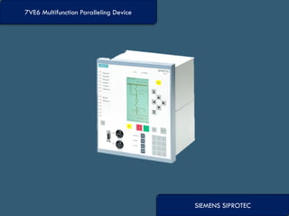
- 1. SIEMENS SIPROTEC 7VE6 Multifunction Paralleling Device
- 2. The 7VE61 and 7VE63 paralleling devices of the SIPROTEC 4 family are multifunctional compact units used for paralleling power systems and generators. Their technical design ensures highly reliable paralleling due to their 1-channel or 2-channel measurement method and their hardware design. This is supported by numerous monitoring functions. The units automatically detect the operating conditions. The response to these conditions depends on settings. In “synchronous network switching” mode, the frequency difference is measured with great accuracy. If the frequency difference is almost zero for a long enough time, the networks are already synchronous and a larger making angle is permissible. If the conditions are asynchronous, as is the case when synchronizing generators, the generator speed is automatically matched to the system frequency and the generator voltage to the system voltage. The connection is then made at the synchronous point, allowing for circuit-breaker make-time. The 7VE61 paralleling device is a 1-channel unit (paralleling function + synchro-check) for use with small to medium-size generators and power systems. It is more reliable than 1- channel paralleling devices. It can also be used for synchro-check, with parallel operation of three synchronization points.
- 3. Consideration of transformer vector group and tap changer Synchronization record (instantaneous or r.m.s. record) Commissioning support (CB-time measurement, test synchronization) Browser operation Full control functionality of SIPROTEC 4 Analog outputs of operational measured values Functions for protection or network decoupling tasks
- 4. High reliability with a two-out-of-two design (1 ½ channels in 7VE61 and 2 channels in 7VE63) Paralleling of asynchronous voltage sources Balancing commands for voltage and speed (frequency) Paralleling of synchronous voltage sources Synchro-check function for manual synchronization Parameter blocks for use on several synchronizing points (7VE61 max. 4 and 7VE63 max. 8) Self-supervision of paralleling function Operational measured values 8 oscillographic fault records
- 5. System interface − IEC 60870-5-103 − IEC 61850 protocol − PROFIBUS-DP − MODBUS RTU and DNP 3.0 Service interface for DIGSI 4 (modem) Front interface for DIGSI 4 Time synchronization via IRIG B/DCF77 ( ) Undervoltage protection(27) Overvoltage protection (59) Frequency protection (81) Rate-of-frequency-change protection (81R) Jump of voltage vector monitoring
- 6. The 7VE61 and 7VE63 paralleling devices of the SIPROTEC 4 family are multifunctional compact units used for paralleling power systems and generators. Their technical design ensures highly reliable paralleling due to their 1½-channel or 2-channel measurement method and their hardware design. This is supported by numerous monitoring functions. The units automatically detect the operating conditions. The response to these conditions depends on settings. In “synchronous network switching” mode, the frequency difference is measured with great accuracy. If the frequency difference is almost zero for a long enough time, the networks are already synchronous and a larger making angle is permissible. If the conditions are asynchronous, as is the case when synchronizing generators, the generator speed is automatically matched to the system frequency and the generator voltage to the system voltage. The connection is then made at the synchronous point, allowing for circuit-breaker make-time. The 7VE61 paralleling device is a 1½-channel unit (paralleling function + synchro- check) for use with small to medium-size generators and power systems
- 7. Indications: The SIPROTEC 4 units provide detailed data for analysis of synchronization (fault events from activated protection functions) and for checking states during operation. All indications are protected against power supply failure. o Synchronization indications (Fault indications) The last eight synchronizations (faults) are stored in the unit at all times. A fresh synchronization (fault) will erase the oldest one. The fault indications have a time resolution of 1 ms. They provide detailed information on history. The buffer memory is designed for a total of 600 indications. o Operational indications All indications that are not directly associated with the synchronization (fault) (e.g. operating or switching actions) are stored in the status indication buffer. The time resolution is 1 ms, buffer size: 200 indications.
- 10. Mob No: Mr. Piyush Rathi- +91-9819614841 Website: www.reliservsolution.com Email-ID: piyush@reliserv.in sales1@reliserv.in Address: Office No: 9, Space Heights, Plot No. 53/54 , Sector 34, Kamothe,Navi Mumbai- 410209