
Recommended
More Related Content
Similar to unit-2_DL.pdf
Similar to unit-2_DL.pdf (20)
Recently uploaded
Recently uploaded (20)
unit-2_DL.pdf
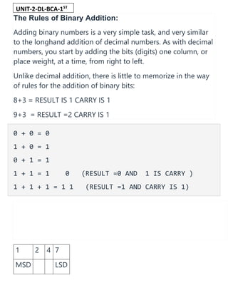
- 1. The Rules of Binary Addition: Adding binary numbers is a very simple task, and very similar to the longhand addition of decimal numbers. As with decimal numbers, you start by adding the bits (digits) one column, or place weight, at a time, from right to left. Unlike decimal addition, there is little to memorize in the way of rules for the addition of binary bits: 8+3 = RESULT IS 1 CARRY IS 1 9+3 = RESULT =2 CARRY IS 1 0 + 0 = 0 1 + 0 = 1 0 + 1 = 1 1 + 1 = 1 0 (RESULT =0 AND 1 IS CARRY ) 1 + 1 + 1 = 1 1 (RESULT =1 AND CARRY IS 1) 1 2 4 7 MSD LSD UNIT-2-DL-BCA-1ST SEM
- 2. MOST SIGNIFICANT DIGIT = ITS PLACE IS HIGHEST =1X1000=1000 PLACE VALUE OF 2 =2X100=200 PLACE VALUE OF 4 =4X10=40 LEAST SIGNIUFICANT DIGIT = ITS PLACE VALUE IS LOWEST =7X1=7 (1000+200+40+7)=1247 Just as with decimal addition, when the sum in one column is a two-bit (two-digit) number, the least significant figure is written as part of the total sum and the most significant figure is “carried” to the next left column. Consider the following examples: The addition problem on the left did not require any bits to be carried since the sum of bits in each column was either 1 or 0, not 10 or 11. In the other two problems, there definitely were bits to be carried, but the process of addition is still quite simple.
- 3. Binary Addition is the Foundation of Digital Computers As we’ll see later, there are ways that electronic circuits can be built to perform this very task of addition, by representing each bit of each binary number as a voltage signal (either “high,” for a 1; or “low” for a 0). This is the very foundation of all the arithmetic which modern digital computers perform. SUBTRACTION: With addition being easily accomplished, we can perform the operation of subtraction with the same technique simply by making one of the numbers negative. For example, the subtraction problem of 7 - 5 is essentially the same as the addition problem 7 + (-5). Since we already know how to represent positive numbers in binary, all we need to know now is how to represent their negative counterparts and we’ll be able to subtract. 72- 23= 72+ (-23) Usually we represent a negative decimal number by placing a minus sign directly to the left of the most significant digit, just
- 4. as in the example above, with -5. However, the whole purpose of using binary notation is for constructing on/off circuits that can represent bit values in terms of voltage (2 alternative values: either “high” or “low”). ( + AND – SYMBOLS ARE NOT ALLOWED TO BE USED IN BINARY SYSTEM) In this context, we don’t have the luxury of a third symbol such as a “minus” sign, since these circuits can only be on or off (two possible states). One solution is to reserve a bit (circuit) that does nothing but represent the mathematical sign: (1101 )2 = (-5)10
- 5. (U HAVE TO DECIDE HOW MANY BITS U ARE TAKING TO STORE THE VALUE) As you can see, we have to be careful when we start using bits for any purpose other than standard place-weighted values. Otherwise, 11012 could be misinterpreted as the number thirteen when in fact we mean to represent negative five. To keep things straight here, we must first decide how many bits are going to be needed to represent the largest numbers we’ll be dealing with, and then be sure not to exceed that bit field length in our arithmetic operations. For the above example, I’ve limited myself to the representation of numbers from negative seven (11112) to positive seven (01112), and no more, by making the fourth bit the “sign” bit. Only by first establishing these limits can I avoid confusion of a negative number with a larger, positive number. Representing negative five as 11012 is an example of the sign-magnitude system of negative binary numeration. By using the leftmost bit as a sign indicator and not a place-weighted value, I am sacrificing the “pure” form of binary notation for something that gives me a practical advantage: the representation of negative numbers. The leftmost bit is read as the sign, either positive or negative, and the remaining bits are interpreted according to the standard binary notation: left to right, place weights in multiples of two. Complementation As simple as the sign-magnitude approach is, it is not very practical for arithmetic purposes. For instance, how do I add a negative five (11012) to any other number, using the standard technique for binary addition? I’d have to invent a new way of doing addition in order for it to work, and if I do that, I might as well just do the job with longhand subtraction; there’s no arithmetical advantage to using negative numbers to perform subtraction through addition if we have to do it with sign-magnitude numeration, and that was our goal!
- 6. There’s another method for representing negative numbers which works with our familiar technique of longhand addition, and also happens to make more sense from a place-weighted numeration point of view, called complementation. With this strategy, we assign the leftmost bit to serve a special purpose, just as we did with the sign-magnitude approach, defining our number limits just as before. However, this time, the leftmost bit is more than just a sign bit; rather, it possesses a negative place-weight value. For example, a value of negative five would be represented as such: With the right three bits being able to represent a magnitude from zero through seven, and the leftmost bit representing either zero or negative eight, we can successfully represent any integer number from negative seven (10012 = -810 + 12 = - 710) to positive seven (01112 = 010 + 710 = 710).
- 7. Representing positive numbers in this scheme (with the fourth bit designated as the negative weight) is no different from that of ordinary binary notation. However, representing negative numbers is not quite as straightforward: Binary Subtraction Using 1’s Complement • The number 0 represents the positive sign • The number 1 represents the negative sign Procedures for Binary Subtraction by 1’s Complement • Write the 1’s complement of the subtrahend • Then add the 1’s complement subtrahend with the minuend • If the result has a carryover, then add that carry over in the least significant bit • If there is no carryover, then take the 1’s complement of the resultant, and it is negative. Binary Subtraction Questions Using 1’s Compement Question 1: (110101)2 – (100101)2 Solution: (1 1 0 1 0 1)2 = 5310 (1 0 0 1 0 1)2 = 3710 – subtrahend= 011010 Now take the 1’s complement of the subtrahend and add with minuend. 1 carry
- 8. 1 1 0 1 0 1 (+) 0 1 1 0 1 0 —————— 0 0 1 1 1 1 1 carry —————— 0 1 0 0 0 0 Therefore, the solution is 010000 (010000)2 = 1610 Question 2: (101011)2 – (111001)2 Solution: Take 1’s complement of the subtrahend 1 1 1 1 0 1 0 1 1 (+) 0 0 0 1 1 0 (1’s complement) —————— 1 1 0 0 0 1 Now take the 1’s complement of the resultant since it does not carry 1 The resultant becomes 0 0 1 1 1 0 Now, add the negative sign to the resultant value Therefore the solution is – (001110)2. What is Binary Subtraction?
- 9. Binary subtraction, unlike decimal subtraction, involves only two digits, i.e. 0 and 1. What are the Rules of Binary Subtraction? There are four rules of binary subtraction which are: • 0 – 0 = 0 • 0 – 1 = 1 ( with a borrow of 1) • 1 – 0 = 1 • 1 – 1 = 0 What is the binary subtraction of 1111011.11 and 1010101.10? By subtracting 1010101.10 from 1111011.11 we get; 1111011.11 – 1010101.10 ——————– 100110.01 ——————– What is the difference between binary addition and binary subtraction? In case of binary addition, when 1 is added to 1, it is equal to 0, and 1 carry forward to the next high order digit. In case of binary subtraction, when 1 is subtracted from 0, then we borrow 1 from next order digit and get the remainder as 1. What signs dies the binary digit 0 and 1 represents? 0 represent positive sign (+) 1 represent negative sign (-)
- 10. Subtraction by 2’s Complement With the help of subtraction by 2’s complement method we can easily subtract two binary numbers. The operation is carried out by means of the following steps: (i) At first, 2’s complement of the subtrahend is found. (ii) Then it is added to the minuend. (iii) If the final answer has a carryover of the sum is 1, it is dropped and the result is positive. (iv) If there is no carry over, the two’s complement of the sum will be the result and it is negative. The following examples on subtraction by 2’s complement will make the procedure clear: Evaluate: (i) 110110 - 10110 Solution: The numbers of bits in the subtrahend is 5 while that of minuend is 6. We make the number of bits in the subtrahend equal to that of minuend by taking a `0’ in the sixth place of the subtrahend. Now, 2’s complement of 010110 is (010110 + 1) i.e.101010. Adding this with the minuend. 1 1 0 1 1 0 Minuend 1 0 1 0 1 0 2’s complement of subtrahend Carry over 1 1 0 0 0 0 0 Result of addition After dropping the carry over we get the result of subtraction to be 100000.
- 11. (ii) 10110 – 11010 Solution: 2’s complement of 11010 is (00101 + 1) i.e. 00110. Hence Minued - 1 0 1 1 0 2’s complement of subtrahend - 0 0 1 1 0 Result of addition - 1 1 1 0 0 As there is no carry over, the result of subtraction is negative and is obtained by writing the 2’s complement of 11100 i.e.(00011 + 1) or 00100. Hence the difference is – 100. (iii) 1010.11 – 1001.01 Solution: 2’s complement of 1001.01 is 0110.11. Hence Minued - 1 0 1 0 . 1 1 2’s complement of subtrahend - 0 1 1 0 . 1 1 Carry over 1 0 0 0 1 . 1 0 After dropping the carry over we get the result of subtraction as 1.10. (iv) 10100.01 – 11011.10 Solution: 2’s complement of 11011.10 is 00100.10. Hence Minued - 1 0 1 0 0 . 0 1 2’s complement of subtrahend - 0 0 1 0 0. 1 0 Result of addition - 1 1 0 0 0 . 1 1
- 12. As there is no carry over the result of subtraction is negative and is obtained by writing the 2’s complement of 11000.11. Hence the required result is – 00111.01. (More examples on 2’s complement addition and subtraction ) When negative numbers are expressed in binary addition using 2’s complement the addition of binary numbers becomes easier. This operation is almost similar to that in 1’s complement system and is explained with examples given below: A. Addition of a positive number and a negative number. We consider the following cases. Case I: When the positive number has a greater magnitude In this case the carry which will be generated is discarded and the final result is the result of addition. The following examples will illustrate this method in binary addition using 2’s complement: In a 5-bit register find the sum of the following by using 2’s complement: (i) +1011 and – (0101) or in decimal (11) 10 - (5)10 Solution: + 1 0 1 1 ⇒ 0 1 0 1 1 - 0 1 0 1 ⇒ 1 1 0 1 1 (2’s complement)
- 13. (Carry 1 discarded) 0 0 1 1 0 Hence the sum is + 0110. (ii) + 0111 and – 0011. Solution: + 0 1 1 1 ⇒ 0 0 1 1 1 - 0 0 1 1 ⇒ 1 1 1 0 1 (Carry 1 discarded) 0 0 1 0 0 Hence the sum is + 0100. Case II: When the negative number is greater. When the negative numbers is greater no carry will be generated in the sign bit. The result of addition will be negative and the final result is obtained by taking 2’s complement of the magnitude bits of the result. The following examples will illustrate this method in binary addition using 2’s complement: In a 5-bit register find the sum of the following by using 2’s complement: (i) + 0 0 1 1 and - 0 1 0 1 Solution: + 0 0 1 1 ⇒ 0 0 0 1 1 - 0 1 0 1 ⇒ 1 1 0 1 1 (2’s complement) 1 1 1 1 0
- 14. 2’s complement of 1110 is (0001 + 0001) or 0010. Hence the required sum is - 0010. (ii) + 0 1 0 0 and - 0 1 1 1 Solution: + 0 1 0 0 ⇒ 0 0 1 0 0 - 0 1 1 1 ⇒ 1 1 0 0 1 (2’s complement) 1 1 1 0 1 2’s complement of 1101 is 0011. Hence the required sum is – 0011. B. When the numbers are negative. When two negative numbers are added a carry will be generated from the sign bit which will be discarded. 2’s complement of the magnitude bits of the operation will be the final sum. The following examples will illustrate this method in binary addition using 2’s complement: In a 5-bit register find the sum of the following by using 2’s complement: (i) – 0011 and – 0101 Solution:
- 15. - 0 0 1 1 ⇒ 1 1 1 0 1 (2’s complement) - 0 1 0 1 ⇒ 1 1 0 1 1 (2’s complement) (Carry 1 discarded) 1 1 0 0 0 2’s complement of 1000 is (0111 + 0001) or 1000. Hence the required sum is – 1000. (ii) -0111 and – 0010. Solution: - 0 1 1 1 ⇒ 1 1 0 0 1 (2’s complement) - 0 0 1 0 ⇒ 1 1 1 1 0 (2’s complement) (Carry 1 discarded) 1 0 1 1 1 2’s complement of 0111 is 1001. Hence the required sum is – 1001. The Digital Logic “Exclusive-OR” Gate 2-input Ex-OR Gate Symbol Truth Table 2-input Ex-OR Gate B A Q 0 0 0 0 1 1 1 0 1
- 16. 1 1 0 Boolean Expression Q = A ⊕ B A OR B but NOT BOTH gives Q Giving the Boolean expression of: Q = AB + AB The truth table above shows that the output of an Exclusive-OR gate ONLY goes “HIGH” when both of its two input terminals are at “DIFFERENT” logic levels with respect to each other. If these two inputs, A and B are both at logic level “1” or both at logic level “0” the output is a “0” making the gate an “odd but not the even gate”. In other words, the output is “1” when there are an odd number of 1’s in the inputs. This ability of the Exclusive-OR gate to compare two logic levels and produce an output value dependent upon the input condition is very useful in computational logic circuits as it gives us the following Boolean expression of: Q = (A ⊕ B) = A.(B)’ + (A)’.B The logic function implemented by a 2-input Ex-OR is given as either: “A OR B but NOT both” will give an output at Q. In general, an Ex-OR gate will give an output value of logic “1” ONLY when there are an ODD number of 1’s on the inputs to the gate, if the two numbers are equal, the output is “0”. Then an Ex-OR function with more than two inputs is called an “odd function” or modulo-2-sum (Mod-2-SUM), not an Ex-OR. This description can be expanded to apply to any number of individual inputs as shown below for a 3- input Ex-OR gate. 3-input Ex-OR Gate Symbol Truth Table 3-input Ex-OR Gate C B A Q 0 0 0 0 0 0 1 1 0 1 0 1
- 17. 0 1 1 0 1 0 0 1 1 0 1 0 1 1 0 0 1 1 1 1 Boolean Expression Q = A ⊕ B ⊕ C “Any ODD Number of Inputs” gives Q Giving the Boolean expression of: Q = ABC + ABC + ABC + ABC The symbol used to denote an Exclusive-OR odd function is slightly different to that for the standard Inclusive-OR Gate. The logic or Boolean expression given for a logic OR gate is that of logical addition which is denoted by a standard plus sign. The symbol used to describe the Boolean expression for an Exclusive-OR function is a plus sign, ( + ) within a circle ( Ο ). This exclusive-OR symbol also represents the mathematical “direct sum of sub-objects” expression, with the resulting symbol for an Exclusive-OR function being given as: ( ⊕ ). We said previously that the Ex-OR function is not a basic logic gate but a combination of different logic gates connected together. Using the 2-input truth table above, we can expand the Ex- OR function to: (A+B).(A.B) which means that we can realise this new expression using the following individual gates. Difference between Half adder and full adder 1. Half Adder : Half Adder is a combinational logic circuit which is designed by connecting one EX- OR gate and one AND gate. The half adder circuit has two inputs: A and B, which add two input digits and generates a carry and a sum.It can add only two bits .we can do following operation and getting desired outputs. bits Result of sum Result of carry 0+0 0 0 0+1 1 0 1+0 1 0 1+1 0 1 0+0= >sum =0 carry =0 0+1= > sum=1 , carry =0 1+0= > sum=1 ,carry =0
- 18. 1+1= sum=0 ,carry =1 The output obtained from the EX-OR gate is the sum of the two numbers while that obtained by AND gate is the carry. There will be no forwarding of carry addition because there is no logic gate to process that. Thus, this is called Half Adder circuit. Logical Expression : Sum = A XOR B Carry = A AND B
- 19. 2. Full Adder : Full Adder is the circuit which consists of two EX-OR gates, two AND gates and one OR gate. Full Adder is the adder which adds three inputs and produces two outputs which consists of two EX-OR gates, two AND gates and one OR gate. The first two inputs are A and B and the third input is an input carry as C-IN. The output carry is designated as C-OUT and the normal output is designated as S which is SUM. Equation obtained by EX-OR gate is the sum of the binary digits. While the output obtained by AND gate is the carry obtained by addition. Truth Table : Logical Expression : SUM = (A XOR B) XOR Cin = (A ⊕ B) ⊕ Cin CARRY-OUT = A AND B OR Cin(A XOR B) = A.B + Cin(A ⊕ B)
- 20. Full Adder This adder is difficult to implement when compared to half-adder. Full Adder Functional Diagram The difference between a half-adder and a full-adder is that the full-adder has three inputs and two outputs, whereas half adder has only two inputs and two outputs. The first two inputs are A and B and the third input is an input carry as C-IN. When a full- adder logic is designed, you string eight of them together to create a byte-wide( 8 BIT) adder and cascade the carry bit from one adder to the next. FULL ADDER Truth Table The output carry is designated as C-OUT and the normal output is represented as S which is ‘SUM’. With the above full adder truth-table, the implementation of a full adder circuit can be understood easily. The SUM ‘S’ is produced in two steps: 1. By XORing the provided inputs ‘A’ and ‘B’ 2. The result of A XOR B is then XORed with the C-IN
- 21. This generates SUM and C-OUT is true only when either two of three inputs are HIGH, then the C-OUT will be HIGH. So, we can implement a full adder circuit with the help of two half adder circuits. Initially, the half adder will be used to add A and B to produce a partial Sum and a second-half adder logic can be used to add C-IN to the Sum produced by the first half adder to get the final S output. If any of the half adder logic produces a carry, there will be an output carry. So, C-OUT will be an OR function of the half-adder Carry outputs. Take a look at the implementation of the full adder circuit shown below. Full Adder Logical Diagram The implementation of larger logic diagrams is possible with the above full adder logic a simpler symbol is mostly used to represent the operation. Given below is a simpler schematic representation of a one-bit full adder. With this type of symbol, we can add two bits together, taking a carry from the next lower order of magnitude, and sending a carry to the next higher order of magnitude. In a computer, for a multi-bit operation, each bit must be represented by a full adder and must be added simultaneously. Thus, to add two 8-bit numbers, you will need 8 full adders which can be formed by cascading two of the 4-bit blocks.
- 24. Consider the full adder circuit shown above with corresponding truth table. We define two variables
- 26. Unsigned Binary multiplication: WE ARE GOING TO ADD TWO BINARY NUMBERS IN DIGITAL LOGIC LET US MULTIPLY 11X13 =143=10001111 11=(1011)2=M( MULTIPLICAND) 13=(1101)2=Q ( MULTIPLIER) • HERE ASSUMING THAT WE ARE TAKING 4 BIT NUMBER • N=4=COUNT • C=SINGLE BIT FOR CARRY • A= IS A 4 BIT NUMBER INITIALISED WITH 0 (i.e 0000) • Q0 IS THE LSB OF Q (INITIALLY IT IS 1) RESULT= 1000 1111
- 28. 2 ‘s complement multiplication using Booth’s algorithm:
- 29. Here we are doing QXM and the answer we get in the register AQ
- 31. Let us multiply Q 5 ( 0101 ) with M 7 (0111). Here answer is AQ 35 the binary equivalent is 00100011)
- 32. Another example for multiplication of -5 and 4 :
- 37. IEEE Standard 754 Floating Point Numbers The IEEE Standard for Floating-Point Arithmetic (IEEE 754) is a technical standard for floating-point computation which was established in 1985 by the Institute of Electrical and Electronics Engineers (IEEE). The standard addressed many problems found in the diverse floating point implementations that made them difficult to use reliably and reduced their portability. IEEE Standard 754 floating point is the most common representation today for real numbers on computers, including Intel-based PC’s, Macs, and most Unix platforms.
- 38. There are several ways to represent floating point number but IEEE 754 is the most efficient in most cases. IEEE 754 has 3 basic components: 1. The Sign of Mantissa – This is as simple as the name. 0 represents a positive number while 1 represents a negative number. 2. The Biased exponent – The exponent field needs to represent both positive and negative exponents. A bias is added to the actual exponent in order to get the stored exponent. 3. The Normalised Mantissa – The mantissa is part of a number in scientific notation or a floating-point number, consisting of its significant digits. Here we have only 2 digits, i.e. O and 1. So a normalised mantissa is one with only one 1 to the left of the decimal. IEEE 754 numbers are divided into two based on the above three components: single precision and double precision.