Download as PDF, PPTX
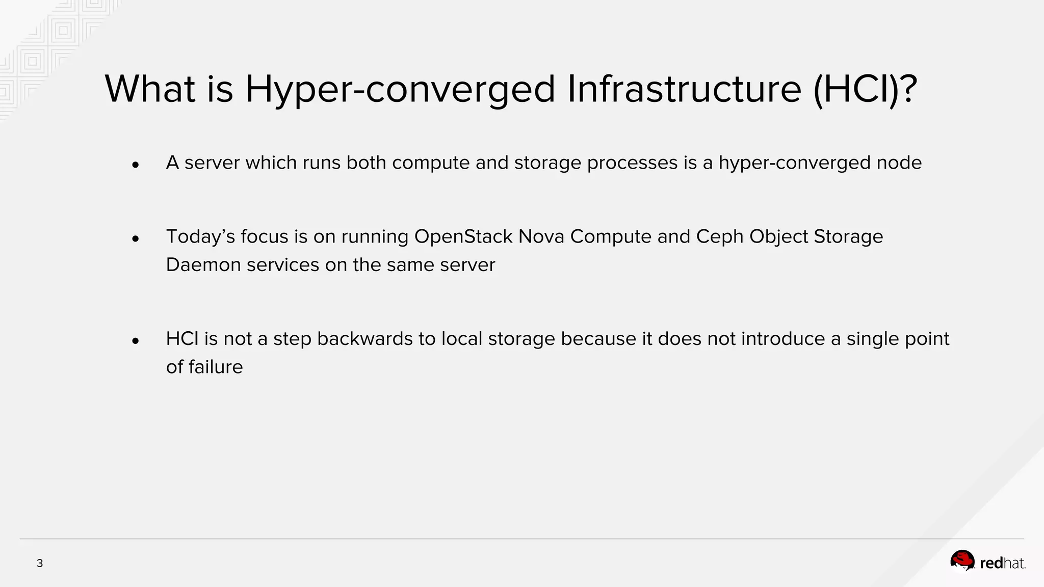
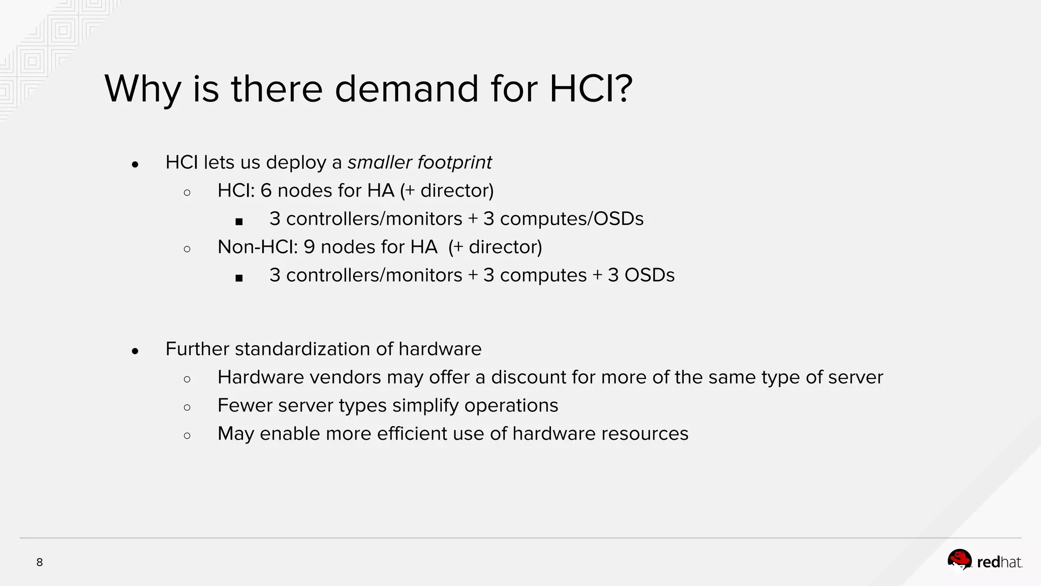

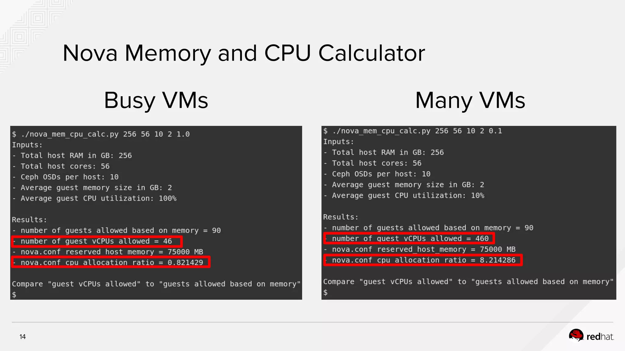
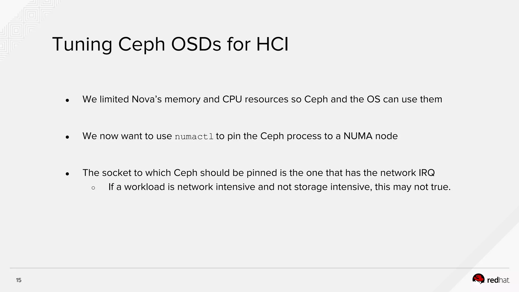
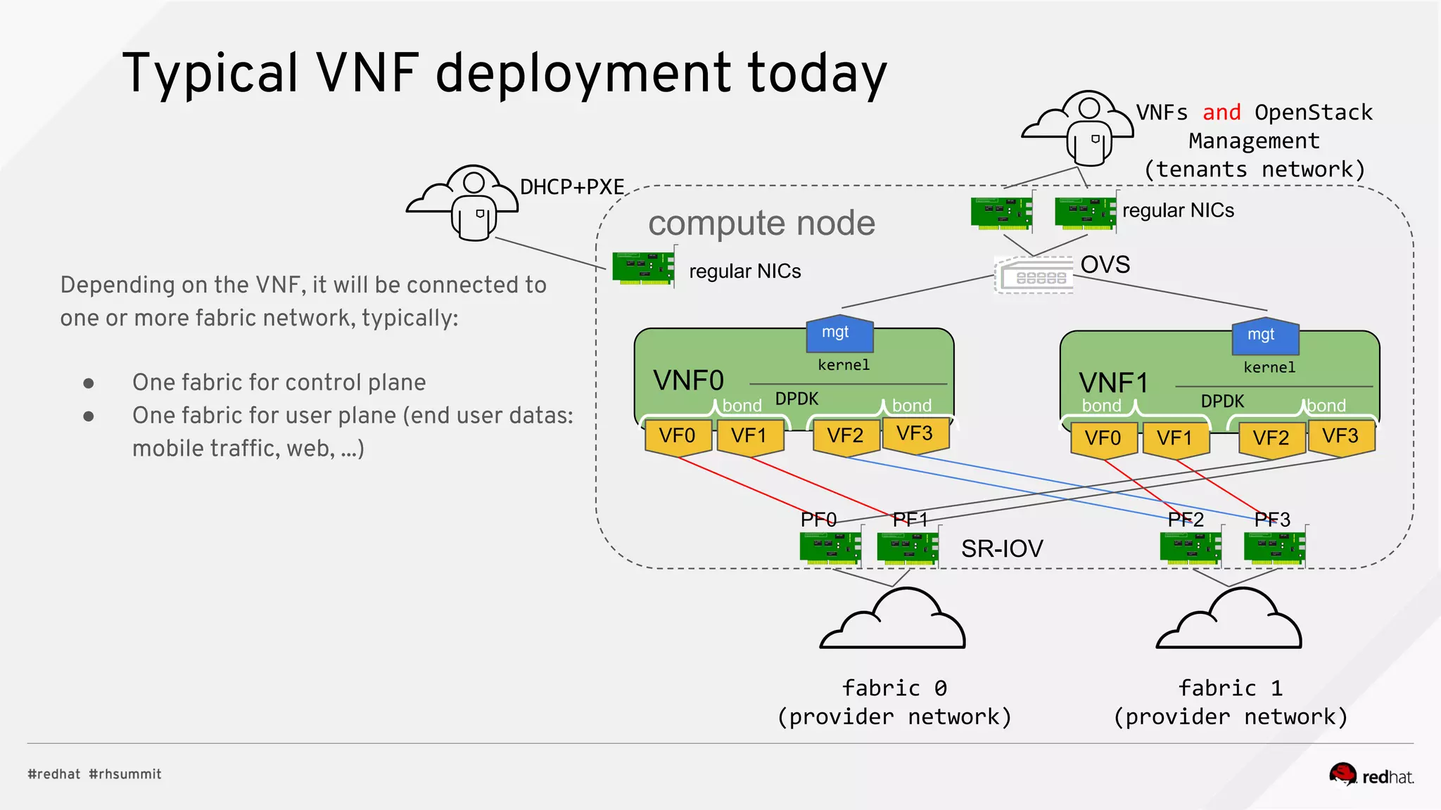
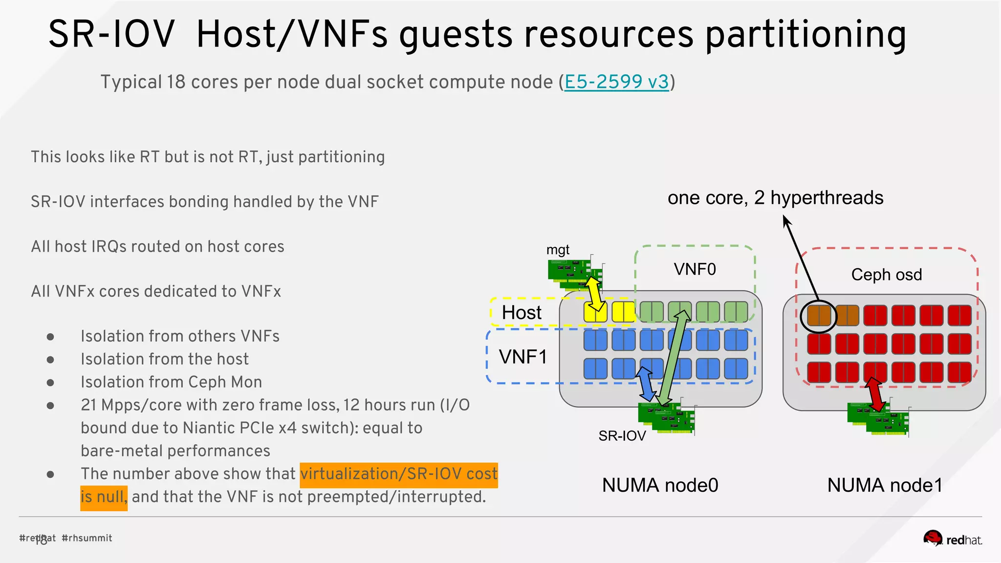
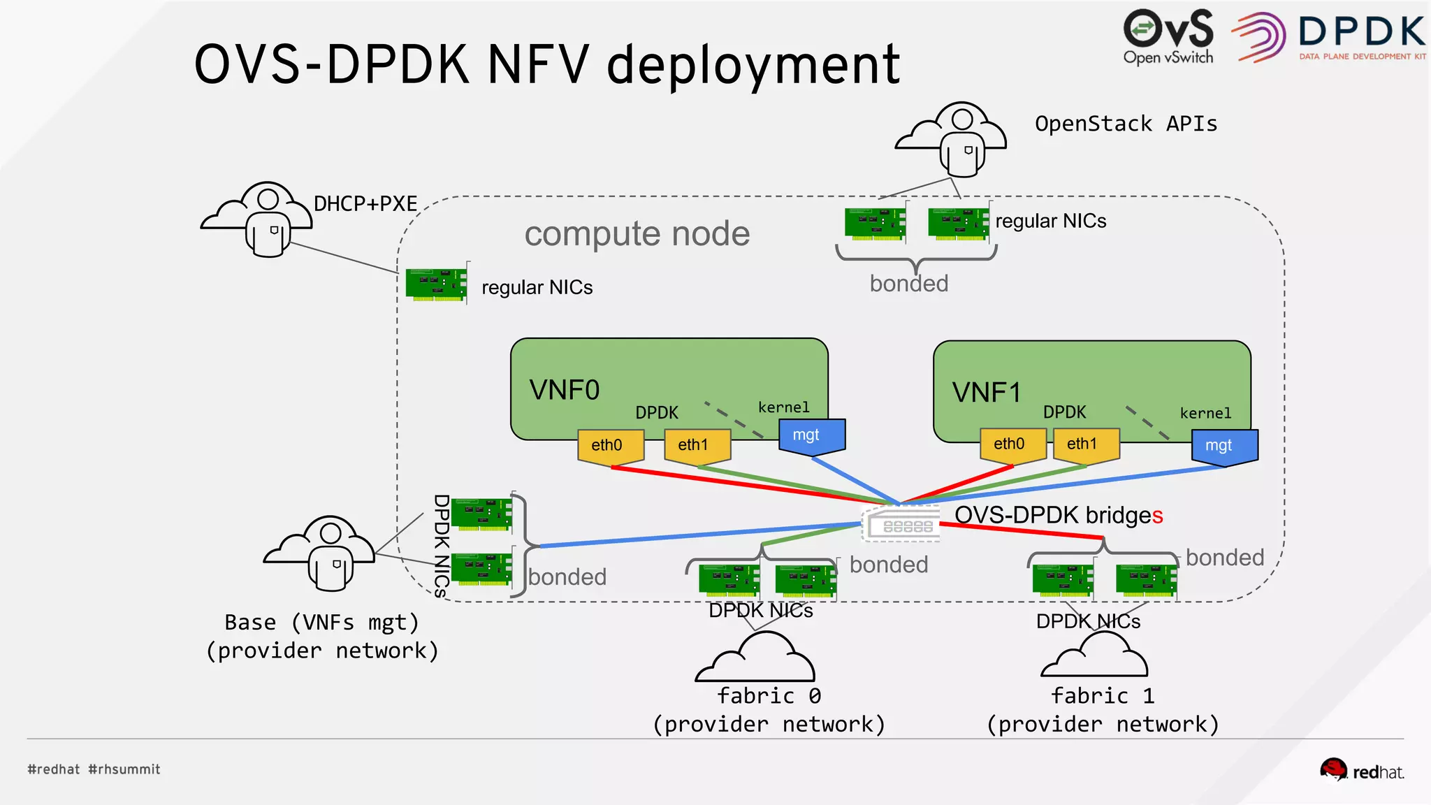
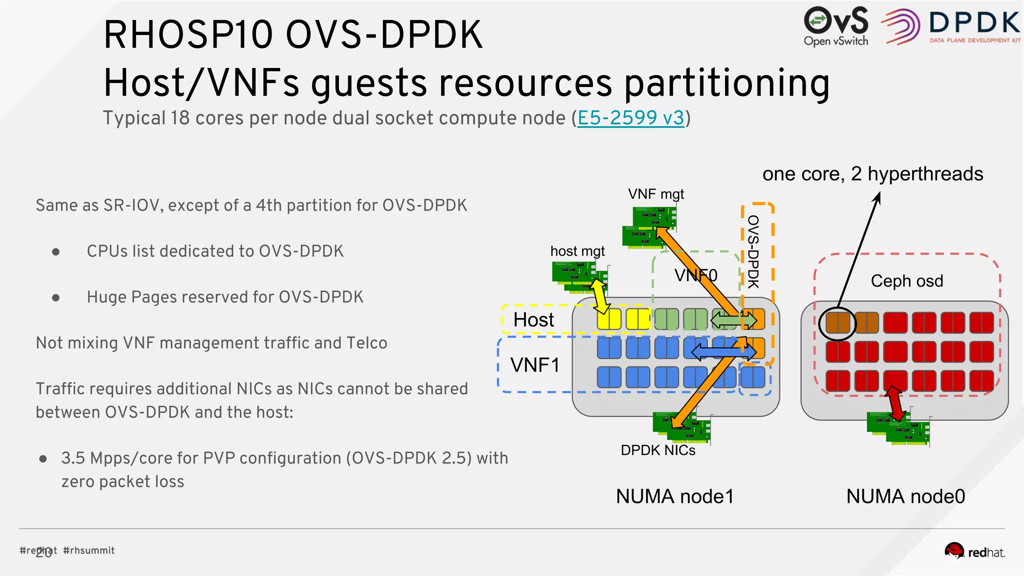
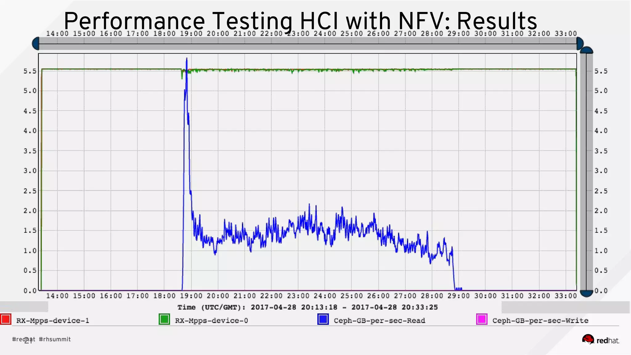
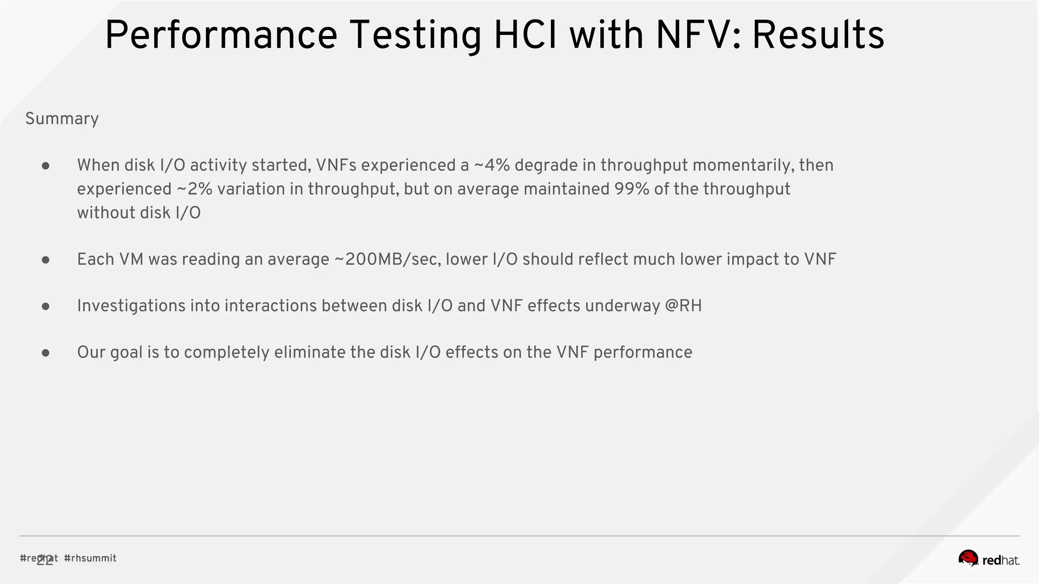

The document discusses hyper-converged infrastructure (HCI) and its integration with OpenStack and Ceph for improved resource management and efficiency. It highlights the advantages of HCI, including reduced footprint, better hardware standardization, and isolation for network function virtualization (NFV). Performance testing results indicate that VNFs maintained high throughput with minimal impact from disk I/O activities.


![Vibe Coding vs. Spec-Driven Development [Free Meetup]](https://cdn.slidesharecdn.com/ss_thumbnails/vibecodingvsspecdrivendevelopment-251209105622-43f455e7-thumbnail.jpg?width=640&height=640&fit=bounds)


![Coded Agents – with UiPath SDK + LangGraph [Virtual Hands-on Workshop]](https://cdn.slidesharecdn.com/ss_thumbnails/codedagentsdeck-251215155422-5497c599-thumbnail.jpg?width=640&height=640&fit=bounds)


