Determine if an auxiliary power supply is needed for the GSMX GSM Communicator
•
0 likes•320 views

This document provides instructions for determining if an auxiliary power supply is needed to power a GSMX GSM Communicator device when installing it on a security control panel. It lists the maximum auxiliary power capacities for popular control panel models. It outlines a 3-step process to 1) determine the control panel's available power, 2) calculate the total current draw of all existing devices, and 3) check if the available power can support the GSMX's 200mA requirement. If not, an auxiliary power supply must be installed.

Recommended
More Related Content
What's hot
What's hot (20)
Similar to Determine if an auxiliary power supply is needed for the GSMX GSM Communicator
Similar to Determine if an auxiliary power supply is needed for the GSMX GSM Communicator (20)
More from Alarm Grid
More from Alarm Grid (20)
Determine if an auxiliary power supply is needed for the GSMX GSM Communicator
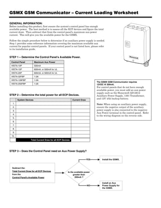
- 1. GSMX GSM Communicator – Current Loading Worksheet GENERAL INFORMATION: Before installing this product, first ensure the system's control panel has enough available power. The best method is to assess all the ECP devices and figure the total current draw. Then subtract that from the control panel's maximum aux power current. This will give you the available power for the GSMX. Follow the simple procedure below to determine if an auxiliary power supply is needed. Step 1 provides some reference information covering the maximum available aux REG TX/RX FAULT current for popular control panels. If your control panel is not listed here, please refer SIGNA L to its installation guide. STEP 1 – Determine the Control Panel's Available Power. Control Panel Maximum Aux Power VISTA-10P 500mA VISTA-15P 600mA, or 500mA for UL VISTA-20P 600mA, or 500mA for UL VISTA-32FBP 1.0A VISTA-128FBP 1.0A The GSMX GSM Communicator requires VISTA-250FBP 1.0A 12VDC @ 200mA. For control panels that do not have enough available power, you must add an aux power supply such as the Honeywell AD12612 STEP 2 – Determine the total power for all ECP Devices. Auxiliary Power Supply, 1361 Transformer, and 12V 4Ah backup battery. System Devices Current Draw 1. Note: When using an auxiliary power supply, 2. ensure the negative output of the auxiliary 3. power supply is also connected to the negative Aux Power terminal in the control panel. Refer 4. to the wiring diagram on the reverse side. 5. 6. 7. 8. 9. 10. Total Current Draw for all ECP Devices STEP 3 – Does the Control Panel need an Aux Power Supply? YES Install the GSMX. Subtract the: Total Current Draw for all ECP Devices Is the available power from the greater than Control Panel's Available Power 200mA ? Install an Aux NO Power Supply for the GSMX.
- 2. Using an Auxiliary Power Supply to power the GSMX GSM Communicator. GSMX AD12612 Communicator Auxiliary Power Supply RED ECP BLACK Cable + (supplied) – YELLOW AC Vista Control Panel GREEN AC DATA OUT DATA IN AUX Pwr – BLACK BLK RED – 4AH Battery 2 Corporate Center Drive, Suite 100 P.O. Box 9040, Melville, NY 11747 Copyright ! 2009 Honeywell International Inc. Ê800-05242zŠ www.honeywell.com/security 800-05242 12/09 Rev. A