SlideShare a Scribd company logo
1 of 105
Download to read offline
Theory of Computation
Prof. K. Adisesha 1
Theory of Computation and Automata (TOC)
Introduction of Theory of Computation
Theory Of Computation is a theoretical branch of Computer Science and Mathematics, which
mainly deals with the logic of computation with respect to simple machines, referred to as
automata.
Automata* enables the scientists to understand how machines compute the functions and solve
problems. The main motivation behind developing Automata Theory was to develop methods to
describe and analyse the dynamic behaviour of discrete systems.
Basic terminologies, used in Theory of Computation:
Symbol:
Symbol (often also called character) is the smallest building block, which can be any alphabet,
letter or any picture.
A, B, C, a, b, c, d, 1, 2
Alphabets (Σ): Alphabets are a finite set of symbols. It is denoted by ∑.
String:
String is a finite sequence of symbols from some alphabet. String is generally denoted as w and
length of a string is denoted as |w|.
Number of Strings (of length 2) that can be generated over the alphabet {a, b} –
Example 1:
If ∑ = {a, b}, various string that can be generated from ∑ are {ab, aa, aaa, bb, bbb, ba, aba.....}.
A string with zero occurrences of symbols is known as an empty string. It is represented by ε.
Theory of Computation
Prof. K. Adisesha 2
The number of symbols in a string w is called the length of a string. It is denoted by |w|.
Language:
A language is a collection of appropriate string. A language which is formed over Σ can be Finite
or Infinite.
Example: 1
L1 = {Set of string of length 2}
= {aa, bb, ba, bb} Finite Language
Example: 2
L2 = {Set of all strings starts with 'a'}
= {a, aa, aaa, abb, abbb, ababb } Infinite Language
A language is a set of strings, chosen from some Σ* or we can say- ‘A language is a subset of Σ*‘.
A language which can be formed over ‘ Σ ‘ can be Finite or Infinite.
Theory of automata
Theory of automata is a theoretical branch of computer science and mathematical. It is the study
of abstract machines and the computation problems that can be solved using these machines. The
abstract machine is called the automata. An automaton with a finite number of states is called a
Finite automaton.
Introduction of Finite Automata
Finite Automata (FA) is the simplest machine to recognize patterns. The finite automata or finite
state machine is an abstract machine which have five elements or tuple. It has a set of states and
rules for moving from one state to another but it depends upon the applied input symbol.
Basically, it is an abstract model of digital computer. Following figure shows some essential
features of a general automation.
Figure: Features of Finite Automata
Theory of Computation
Prof. K. Adisesha 3
The above figure shows following features of automata:
1. Input
2. Output
3. States of automata
4. State relation
5. Output relation
A Finite Automata consists of the following:
Formal specification of machine is {Q, Σ, q, F, δ}.
Q : Finite set of states.
Σ : set of Input Symbols.
q : Initial state.
F : set of Final States.
δ : Transition Function.
Types of Automata:
There are two types of finite automata:
➢ DFA (deterministic finite automata)
➢ NFA (non-deterministic finite automata)
1) Deterministic Finite Automata (DFA)
DFA refers to deterministic finite automata. Deterministic refers to the uniqueness of the
computation. In the DFA, the machine goes to one state only for a particular input character.
DFA does not accept the null move.
DFA consists of 5 tuples {Q, Σ, q, F, δ}.
Q : set of all states.
Σ : set of input symbols. (Symbols which machine takes as input)
q : Initial state. (Starting state of a machine)
F : set of final state.
δ : Transition Function, defined as δ : Q X Σ --> Q.
In a DFA, for a particular input character, the machine goes to one state only. A transition
function is defined on every state for every input symbol. Also, in DFA null (or ε) move is not
allowed, i.e., DFA cannot change state without any input character.
For example, below DFA with Σ = {0, 1} accepts all strings ending with 0.
Theory of Computation
Prof. K. Adisesha 4
Figure: DFA with Σ = {0, 1}
One important thing to note is, there can be many possible DFAs for a pattern. A DFA with
minimum number of states is generally preferred.
2) Nondeterministic Finite Automata (NFA)
NFA stands for non-deterministic finite automata. It is used to transmit any number of states for
a particular input. It can accept the null move.
NFA is similar to DFA except following additional features:
1. Null (or ε) move is allowed i.e., it can move forward without reading symbols.
2. Ability to transmit to any number of states for a particular input.
However, these above features don’t add any power to NFA. If we compare both in terms of
power, both are equivalent.
Due to above additional features, NFA has a different transition function, rest is same as DFA.
δ: Transition Function
δ: Q X (Σ U ε ) --> 2 ^ Q.
As you can see in transition function is for any input including null (or ε), NFA can go to any
state number of states.
For example, below is a NFA for above problem
Nondeterministic Finite Automata (NFA)
One important thing to note is, in NFA, if any path for an input string leads to a final state,
then the input string accepted. For example, in above NFA, there are multiple paths for input
string “00”. Since, one of the paths leads to a final state, “00” is accepted by above NFA.
Theory of Computation
Prof. K. Adisesha 5
Some important points about DFA and NFA:
➢ Every DFA is NFA, but NFA is not DFA.
➢ There can be multiple final states in both NFA and DFA.
➢ DFA is used in Lexical Analysis in Compiler.
➢ NFA is more of a theoretical concept.
Transition Diagram
A transition diagram or state transition diagram is a directed graph which can be constructed as
follows:
➢ There is a node for each state in Q, which is represented by the circle.
➢ There is a directed edge from node q to node p labeled a if δ(q, a) = p.
➢ In the start state, there is an arrow with no source.
➢ Accepting states or final states are indicating by a double circle.
Some Notations that are used in the transition diagram:
There is a description of how a DFA operates:
➢ In DFA, the input to the automata can be any string. Now, put a pointer to the start state q
and read the input string w from left to right and move the pointer according to the
transition function, δ. We can read one symbol at a time. If the next symbol of string w is
a and the pointer is on state p, move the pointer to δ(p, a). When the end of the input string
w is encountered, then the pointer is on some state F.
Theory of Computation
Prof. K. Adisesha 6
➢ The string w is said to be accepted by the DFA if r ∈ F that means the input string w is
processed successfully and the automata reached its final state. The string is said to be
rejected by DFA if r ∉ F.
Example 1:
DFA with ∑ = {0, 1} accepts all strings starting with 1.
Solution:
The finite automata can be represented using a transition graph. In the above diagram, the
machine initially is in start state q0 then on receiving input 1 the machine changes its state to q1.
From q0 on receiving 0, the machine changes its state to q2, which is the dead state. From q1 on
receiving input 0, 1 the machine changes its state to q1, which is the final state. The possible
input strings that can be generated are 10, 11, 110, 101, 111......., that means all string starts with
1.
Example 2:
NFA with ∑ = {0, 1} accepts all strings starting with 1.
Solution:
The NFA can be represented using a transition graph. In the above diagram, the machine initially
is in start state q0 then on receiving input 1 the machine changes its state to q1. From q1 on
receiving input 0, 1 the machine changes its state to q1. The possible input string that can be
generated is 10, 11, 110, 101, 111......, that means all string starts with 1.
Transition Table
The transition table is basically a tabular representation of the transition function. It takes two
arguments (a state and a symbol) and returns a state (the "next state").
Theory of Computation
Prof. K. Adisesha 7
A transition table is represented by the following things:
➢ Columns correspond to input symbols.
➢ Rows correspond to states.
➢ Entries correspond to the next state.
➢ The start state is denoted by an arrow with no source.
➢ The accept state is denoted by a star.
Example 1:
Solution:
Transition table of given DFA is as follows:
Present State Next state for Input 0 Next State of Input 1
→q0 q1 q2
q1 q0 q2
*q2 q2 q2
Explanation:
➢ In the above table, the first column indicates all the current states. Under column 0 and 1,
the next states are shown.
➢ The first row of the transition table can be read as, when the current state is q0, on input 0
the next state will be q1 and on input 1 the next state will be q2.
➢ In the second row, when the current state is q1, on input 0, the next state will be q0, and on
1 input the next state will be q2.
➢ In the third row, when the current state is q2 on input 0, the next state will be q2, and on 1
input the next state will be q2.
Theory of Computation
Prof. K. Adisesha 8
➢ The arrow marked to q0 indicates that it is a start state and circle marked to q2 indicates
that it is a final state.
Example 2:
Solution:
Transition table of given NFA is as follows:
Explanation:
➢ The first row of the transition table can be read as, when the current state is q0, on input 0
the next state will be q0 and on input 1 the next state will be q1.
➢ In the second row, when the current state is q1, on input 0 the next state will be either q1
or q2, and on 1 input the next state will be q2.
➢ In the third row, when the current state is q2 on input 0, the next state will be q1, and on 1
input the next state will be q3.
➢ In the fourth row, when the current state is q3 on input 0, the next state will be q2, and on
1 input the next state will be q2.
DFA (Deterministic finite automata)
Present State Next state for Input 0 Next State of Input 1
→q0 q0 q1
q1 q1, q2 q2
q2 q1 q3
*q3 q2 q2
Theory of Computation
Prof. K. Adisesha 9
➢ DFA refers to deterministic finite automata. Deterministic refers to the uniqueness of the
computation. The finite automata are called deterministic finite automata if the machine is
read an input string one symbol at a time.
➢ In DFA, there is only one path for specific input from the current state to the next state.
➢ DFA does not accept the null move, i.e., the DFA cannot change state without any input
character.
➢ DFA can contain multiple final states. It is used in Lexical Analysis in Compiler.
In the following diagram, we can see that from state q0 for input a, there is only one path which is
going to q1. Similarly, from q0, there is only one path for input b going to q2.
Formal Definition of DFA
A DFA is a collection of 5-tuples same as we described in the definition of FA.
Q: finite set of states
∑: finite set of the input symbol
q0: initial state
F: final state
δ: Transition function
Transition function can be defined as:
δ: Q x ∑→Q
Graphical Representation of DFA
A DFA can be represented by digraphs called state diagram. In which:
➢ The state is represented by vertices.
➢ The arc labelled with an input character show the transitions.
➢ The initial state is marked with an arrow.
➢ The final state is denoted by a double circle.
Theory of Computation
Prof. K. Adisesha 10
Example 1:
Q = {q0, q1, q2}
∑ = {0, 1}
q0 = {q0}
F = {q2}
Solution:
Transition Diagram:
Transition Table:
Present State Next state for Input 0 Next State of Input 1
→q0 q0 q1
q1 q2 q1
*q2 q2 q2
Example 2:
DFA with ∑ = {0, 1} accepts all starting with 0.
Solution:
Theory of Computation
Prof. K. Adisesha 11
Explanation:
o In the above diagram, we can see that on given 0 as input to DFA in state q0 the DFA
changes state to q1 and always go to final state q1 on starting input 0. It can accept 00, 01,
000, 001.... etc. It can't accept any string which starts with 1, because it will never go to
final state on a string starting with 1.
Example 3:
DFA with ∑ = {0, 1} accepts all ending with 0.
Solution:
Explanation:
In the above diagram, we can see that on given 0 as input to DFA in state q0, the DFA changes
state to q1. It can accept any string which ends with 0 like 00, 10, 110, 100....etc. It can't accept
any string which ends with 1, because it will never go to the final state q1 on 1 input, so the string
ending with 1, will not be accepted or will be rejected.
Examples of DFA
Example 1:
Design a FA with ∑ = {0, 1} accepts those string which starts with 1 and ends with 0.
Solution:
The FA will have a start state q0 from which only the edge with input 1 will go to the next state.
Theory of Computation
Prof. K. Adisesha 12
In state q1, if we read 1, we will be in state q1, but if we read 0 at state q1, we will reach to state
q2 which is the final state. In state q2, if we read either 0 or 1, we will go to q2 state or q1 state
respectively. Note that if the input ends with 0, it will be in the final state.
Example 2:
Design a FA with ∑ = {0, 1} accepts the only input 101.
Solution:
In the given solution, we can see that only input 101 will be accepted. Hence, for input 101, there
is no other path shown for other input.
Example 3:
Design FA with ∑ = {0, 1} accepts even number of 0's and even number of 1's.
Solution:
This FA will consider four different stages for input 0 and input 1. The stages could be:
Here q0 is a start state and the final state also. Note carefully that a symmetry of 0's and 1's is
maintained. We can associate meanings to each state as:
Theory of Computation
Prof. K. Adisesha 13
q0: state of even number of 0's and even number of 1's.
q1: state of odd number of 0's and even number of 1's.
q2: state of odd number of 0's and odd number of 1's.
q3: state of even number of 0's and odd number of 1's.
Example 4:
Design FA with ∑ = {0, 1} accepts the set of all strings with three consecutive 0's.
Solution:
The strings that will be generated for this particular languages are 000, 0001, 1000, 10001, .... in
which 0 always appears in a clump of 3. The transition graph is as follows:
Example 5:
Design a DFA L(M) = {w | w ε {0, 1}*} and W is a string that does not contain consecutive 1's.
Solution:
When three consecutive 1's occur the DFA will be:
Here two consecutive 1's or single 1 is acceptable, hence
The stages q0, q1, q2 are the final states. The DFA will generate the strings that do not contain
consecutive 1's like 10, 110, 101,..... etc.
Example 6:
Design a FA with ∑ = {0, 1} accepts the strings with an even number of 0's followed by single 1.
Theory of Computation
Prof. K. Adisesha 14
Solution:
The DFA can be shown by a transition diagram as:
NFA (Non-Deterministic finite automata)
o NFA stands for non-deterministic finite automata. It is easy to construct an NFA than DFA
for a given regular language.
o The finite automata are called NFA when there exist many paths for specific input from
the current state to the next state.
o Every NFA is not DFA, but each NFA can be translated into DFA.
o NFA is defined in the same way as DFA but with the following two exceptions, it contains
multiple next states, and it contains ε transition.
In the following image, we can see that from state q0 for input a, there are two next states q1 and
q2, similarly, from q0 for input b, the next states are q0 and q1. Thus it is not fixed or determined
that with a particular input where to go next. Hence this FA is called non-deterministic finite
automata.
Formal definition of NFA:
NFA also has five states same as DFA, but with different transition function, as shown follows:
δ: Q x ∑ →2Q
Theory of Computation
Prof. K. Adisesha 15
where,
Q: finite set of states
∑: finite set of the input symbol
q0: initial state
F: final state
δ: Transition function
Graphical Representation of an NFA
An NFA can be represented by digraphs called state diagram. In which:
1. The state is represented by vertices.
2. The arc labeled with an input character shows the transitions.
3. The initial state is marked with an arrow.
4. The final state is denoted by the double circle.
Example 1:
Q = {q0, q1, q2}
∑ = {0, 1}
q0 = {q0}
F = {q2}
Solution:
Transition diagram:
Transition Table:
Present State Next state for Input 0 Next State of Input 1
→q0 q0, q1 q1
q1 q2 q0
*q2 q2 q1, q2
Theory of Computation
Prof. K. Adisesha 16
In the above diagram, we can see that when the current state is q0, on input 0, the next state will
be q0 or q1, and on 1 input the next state will be q1. When the current state is q1, on input 0 the
next state will be q2 and on 1 input, the next state will be q0. When the current state is q2, on 0
input the next state is q2, and on 1 input the next state will be q1 or q2.
Example 2:
NFA with ∑ = {0, 1} accepts all strings with 01.
Solution:
Transition Table:
Present State Next state for Input 0 Next State of Input 1
→q0 q1 ε
q1 ε q2
*q2 q2 q2
Example 3:
NFA with ∑ = {0, 1} and accept all string of length at least 2.
Solution:
Transition Table:
Present State Next state for Input 0 Next State of Input 1
→q0 q1 q1
q1 q2 q2
*q2 ε
Theory of Computation
Prof. K. Adisesha 17
Examples of NFA
Example 1:
Design a NFA for the transition table as given below:
Present State 0 1
→q0 q0, q1 q0, q2
q1 q3 ε
q2 q2, q3 q3
→q3 q3 q3
Solution:
The transition diagram can be drawn by using the mapping function as given in the table.
Here,
δ(q0, 0) = {q0, q1}
δ(q0, 1) = {q0, q2}
Then, δ(q1, 0) = {q3}
Then, δ(q2, 0) = {q2, q3}
δ(q2, 1) = {q3}
Then, δ(q3, 0) = {q3}
δ(q3, 1) = {q3}
Theory of Computation
Prof. K. Adisesha 18
Example 2:
Design an NFA with ∑ = {0, 1} accepts all string ending with 01.
Solution:
Hence, NFA would be:
Example 3:
Design an NFA with ∑ = {0, 1} in which double '1' is followed by double '0'.
Solution:
The FA with double 1 is as follows:
It should be immediately followed by double 0.
Then,
Now before double 1, there can be any string of 0 and 1. Similarly, after double 0, there can be
any string of 0 and 1.
Hence the NFA becomes:
Theory of Computation
Prof. K. Adisesha 19
Now considering the string 01100011
q0 → q1 → q2 → q3 → q4 → q4 → q4 → q4
Example 4:
Design an NFA in which all the string contain a substring 1110.
Solution:
The language consists of all the string containing substring 1010. The partial transition diagram
can be:
Now as 1010 could be the substring. Hence we will add the inputs 0's and 1's so that the substring
1010 of the language can be maintained. Hence the NFA becomes:
Transition table for the above transition diagram can be given below:
Consider a string 111010,
δ(q1, 111010) = δ(q1, 1100)
= δ(q1, 100)
= δ(q2, 00)
Present State 0 1
→q1 q1 q1, q2
q2 q3
q3 q4
q4 q5
*q5 q5 q5
Theory of Computation
Prof. K. Adisesha 20
Got stuck! As there is no path from q2 for input symbol 0. We can process string 111010 in another
way.
δ(q1, 111010) = δ(q2, 1100)
= δ(q3, 100)
= δ(q4, 00)
= δ(q5, 0)
= δ(q5, ε)
As state q5 is the accept state. We get the complete scanned, and we reached to the final state.
Example 5:
Design an NFA with ∑ = {0, 1} accepts all string in which the third symbol from the right end is
always 0.
Solution:
Thus, we get the third symbol from the right end as '0' always. The NFA can be:
The above image is an NFA because in state q0 with input 0, we can either go to state q0 or q1.
Eliminating ε Transitions
NFA with ε can be converted to NFA without ε, and this NFA without ε can be converted to DFA.
To do this, we will use a method, which can remove all the ε transition from given NFA. The
method will be:
1. Find out all the ε transitions from each state from Q. That will be called as ε-closure{q1}
where qi ∈ Q.
2. Then δ' transitions can be obtained. The δ' transitions mean a ε-closure on δ moves.
3. Repeat Step-2 for each input symbol and each state of given NFA.
4. Using the resultant states, the transition table for equivalent NFA without ε can be built.
Theory of Computation
Prof. K. Adisesha 21
Example:
Convert the following NFA with ε to NFA without ε.
Solutions: We will first obtain ε-closures of q0, q1 and q2 as follows:
ε-closure(q0) = {q0}
ε-closure(q1) = {q1, q2}
ε-closure(q2) = {q2}
Now the δ' transition on each input symbol is obtained as:
δ'(q0, a) = ε-closure(δ(δ^(q0, ε),a))
= ε-closure(δ(ε-closure(q0),a))
= ε-closure(δ(q0, a))
= ε-closure(q1)
= {q1, q2}
δ'(q0, b) = ε-closure(δ(δ^(q0, ε),b))
= ε-closure(δ(ε-closure(q0),b))
= ε-closure(δ(q0, b))
= Ф
Now the δ' transition on q1 is obtained as:
δ'(q1, a) = ε-closure(δ(δ^(q1, ε),a))
= ε-closure(δ(ε-closure(q1),a))
= ε-closure(δ(q1, q2), a)
= ε-closure(δ(q1, a) ∪ δ(q2, a))
= ε-closure(Ф ∪ Ф)
= Ф
Theory of Computation
Prof. K. Adisesha 22
δ'(q1, b) = ε-closure(δ(δ^(q1, ε),b))
= ε-closure(δ(ε-closure(q1),b))
= ε-closure(δ(q1, q2), b)
= ε-closure(δ(q1, b) ∪ δ(q2, b))
= ε-closure(Ф ∪ q2)
= {q2}
The δ' transition on q2 is obtained as:
δ'(q2, a) = ε-closure(δ(δ^(q2, ε),a))
= ε-closure(δ(ε-closure(q2),a))
= ε-closure(δ(q2, a))
= ε-closure(Ф)
= Ф
δ'(q2, b) = ε-closure(δ(δ^(q2, ε),b))
= ε-closure(δ(ε-closure(q2),b))
= ε-closure(δ(q2, b))
= ε-closure(q2)
= {q2}
Now we will summarize all the computed δ' transitions:
δ'(q0, a) = {q0, q1}
δ'(q0, b) = Ф
δ'(q1, a) = Ф
δ'(q1, b) = {q2}
δ'(q2, a) = Ф
δ'(q2, b) = {q2}
The transition table can be:
States a b
→q0 {q1, q2} Ф
*q1 Ф {q2}
*q2 Ф {q2}
Theory of Computation
Prof. K. Adisesha 23
State q1 and q2 become the final state as ε-closure of q1 and q2 contain the final state q2. The
NFA can be shown by the following transition diagram:
Conversion from NFA to DFA
In this section, we will discuss the method of converting NFA to its equivalent DFA. In NFA,
when a specific input is given to the current state, the machine goes to multiple states. It can have
zero, one or more than one move on a given input symbol. On the other hand, in DFA, when a
specific input is given to the current state, the machine goes to only one state. DFA has only one
move on a given input symbol.
Let, M = (Q, ∑, δ, q0, F) is an NFA which accepts the language L(M). There should be equivalent
DFA denoted by M' = (Q', ∑', q0', δ', F') such that L(M) = L(M').
Steps for converting NFA to DFA:
Step 1: Initially Q' = ϕ
Step 2: Add q0 of NFA to Q'. Then find the transitions from this start state.
Step 3: In Q', find the possible set of states for each input symbol. If this set of states is not in Q',
then add it to Q'.
Step 4: In DFA, the final state will be all the states which contain F(final states of NFA)
Example 1:
Convert the given NFA to DFA.
Solution: For the given transition diagram we will first construct the transition table.
Theory of Computation
Prof. K. Adisesha 24
State 0 1
→q0 q0 q1
q1 {q1, q2} q1
*q2 q2 {q1, q2}
Now we will obtain δ' transition for state q0.
δ'([q0], 0) = [q0]
δ'([q0], 1) = [q1]
The δ' transition for state q1 is obtained as:
δ'([q1], 0) = [q1, q2] (new state generated)
δ'([q1], 1) = [q1]
The δ' transition for state q2 is obtained as:
δ'([q2], 0) = [q2]
δ'([q2], 1) = [q1, q2]
Now we will obtain δ' transition on [q1, q2].
δ'([q1, q2], 0) = δ(q1, 0) ∪ δ(q2, 0)
= {q1, q2} ∪ {q2}
= [q1, q2]
δ'([q1, q2], 1) = δ(q1, 1) ∪ δ(q2, 1)
= {q1} ∪ {q1, q2}
= {q1, q2}
= [q1, q2]
The state [q1, q2] is the final state as well because it contains a final state q2. The transition table
for the constructed DFA will be:
State 0 1
→[q0] [q0] [q1]
[q1] [q1, q2] [q1]
*[q2] [q2] [q1, q2]
*[q1, q2] [q1, q2] [q1, q2]
Theory of Computation
Prof. K. Adisesha 25
The Transition diagram will be:
The state q2 can be eliminated because q2 is an unreachable state.
Example 2:
Convert the given NFA to DFA.
Solution: For the given transition diagram we will first construct the transition table.
State 0 1
→q0 {q0, q1} {q1}
*q1 ϕ {q0, q1}
Now we will obtain δ' transition for state q0.
δ'([q0], 0) = {q0, q1}
= [q0, q1] (new state generated)
δ'([q0], 1) = {q1} = [q1]
The δ' transition for state q1 is obtained as:
δ'([q1], 0) = ϕ
δ'([q1], 1) = [q0, q1]
Theory of Computation
Prof. K. Adisesha 26
Now we will obtain δ' transition on [q0, q1].
δ'([q0, q1], 0) = δ(q0, 0) ∪ δ(q1, 0)
= {q0, q1} ∪ ϕ
= {q0, q1}
= [q0, q1]
Similarly,
δ'([q0, q1], 1) = δ(q0, 1) ∪ δ(q1, 1)
= {q1} ∪ {q0, q1}
= {q0, q1}
= [q0, q1]
As in the given NFA, q1 is a final state, then in DFA wherever, q1 exists that state becomes a final
state. Hence in the DFA, final states are [q1] and [q0, q1]. Therefore set of final states F = {[q1],
[q0, q1]}.
The transition table for the constructed DFA will be:
State 0 1
→[q0] [q0, q1] [q1]
*[q1] ϕ [q0, q1]
*[q0, q1] [q0, q1] [q0, q1]
The Transition diagram will be:
Theory of Computation
Prof. K. Adisesha 27
Even we can change the name of the states of DFA.
Suppose
A = [q0]
B = [q1]
C = [q0, q1]
With these new names the DFA will be as follows:
Conversion from NFA with ε to DFA
Non-deterministic finite automata(NFA) is a finite automata where for some cases when a specific
input is given to the current state, the machine goes to multiple states or more than 1 states. It can
contain ε move. It can be represented as M = { Q, ∑, δ, q0, F}.
Where:
Q: finite set of states
∑: finite set of the input symbol
q0: initial state
F: final state
δ: Transition function
NFA with ∈ move: If any FA contains ε transaction or move, the finite automata is called NFA
with ∈ move.
ε-closure: ε-closure for a given state A means a set of states which can be reached from the state
A with only ε(null) move including the state A itself.
Steps for converting NFA with ε to DFA:
Step 1: We will take the ε-closure for the starting state of NFA as a starting state of DFA.
Theory of Computation
Prof. K. Adisesha 28
Step 2: Find the states for each input symbol that can be traversed from the present. That means
the union of transition value and their closures for each state of NFA present in the current state
of DFA.
Step 3: If we found a new state, take it as current state and repeat step 2.
Step 4: Repeat Step 2 and Step 3 until there is no new state present in the transition table of DFA.
Step 5: Mark the states of DFA as a final state which contains the final state of NFA.
Example 1:
Convert the NFA with ε into its equivalent DFA.
Solution:
Let us obtain ε-closure of each state.
ε-closure {q0} = {q0, q1, q2}
ε-closure {q1} = {q1}
ε-closure {q2} = {q2}
ε-closure {q3} = {q3}
ε-closure {q4} = {q4}
Now, let ε-closure {q0} = {q0, q1, q2} be state A.
Hence
δ'(A, 0) = ε-closure {δ((q0, q1, q2), 0) }
= ε-closure {δ(q0, 0) ∪ δ(q1, 0) ∪ δ(q2, 0) }
= ε-closure {q3}
= {q3} call it as state B.
Theory of Computation
Prof. K. Adisesha 29
δ'(A, 1) = ε-closure {δ((q0, q1, q2), 1) }
= ε-closure {δ((q0, 1) ∪ δ(q1, 1) ∪ δ(q2, 1) }
= ε-closure {q3}
= {q3} = B.
The partial DFA will be
Now,
δ'(B, 0) = ε-closure {δ(q3, 0) }
= ϕ
δ'(B, 1) = ε-closure {δ(q3, 1) }
= ε-closure {q4}
= {q4} i.e. state C
For state C:
δ'(C, 0) = ε-closure {δ(q4, 0) }
= ϕ
δ'(C, 1) = ε-closure {δ(q4, 1) }
= ϕ
The DFA will be,
Example 2:
Convert the given NFA into its equivalent DFA.
Theory of Computation
Prof. K. Adisesha 30
Solution: Let us obtain the ε-closure of each state.
ε-closure(q0) = {q0, q1, q2}
ε-closure(q1) = {q1, q2}
ε-closure(q2) = {q2}
Now we will obtain δ' transition. Let ε-closure(q0) = {q0, q1, q2} call it as state A.
δ'(A, 0) = ε-closure{δ((q0, q1, q2), 0)}
= ε-closure{δ(q0, 0) ∪ δ(q1, 0) ∪ δ(q2, 0)}
= ε-closure{q0}
= {q0, q1, q2}
δ'(A, 1) = ε-closure{δ((q0, q1, q2), 1)}
= ε-closure{δ(q0, 1) ∪ δ(q1, 1) ∪ δ(q2, 1)}
= ε-closure{q1}
= {q1, q2} call it as state B
δ'(A, 2) = ε-closure{δ((q0, q1, q2), 2)}
= ε-closure{δ(q0, 2) ∪ δ(q1, 2) ∪ δ(q2, 2)}
= ε-closure{q2}
= {q2} call it state C
Thus we have obtained
δ'(A, 0) = A
δ'(A, 1) = B
δ'(A, 2) = C
The partial DFA will be:
Now we will find the transitions on states B and C for each input.
Theory of Computation
Prof. K. Adisesha 31
Hence
δ'(B, 0) = ε-closure{δ((q1, q2), 0)}
= ε-closure{δ(q1, 0) ∪ δ(q2, 0)}
= ε-closure{ϕ}
= ϕ
δ'(B, 1) = ε-closure{δ((q1, q2), 1)}
= ε-closure{δ(q1, 1) ∪ δ(q2, 1)}
= ε-closure{q1}
= {q1, q2} i.e. state B itself
δ'(B, 2) = ε-closure{δ((q1, q2), 2)}
= ε-closure{δ(q1, 2) ∪ δ(q2, 2)}
= ε-closure{q2}
= {q2} i.e. state C itself
Thus we have obtained
δ'(B, 0) = ϕ
δ'(B, 1) = B
δ'(B, 2) = C
The partial transition diagram will be
Now we will obtain transitions for C:
δ'(C, 0) = ε-closure{δ(q2, 0)}
= ε-closure{ϕ}
= ϕ
δ'(C, 1) = ε-closure{δ(q2, 1)}
= ε-closure{ϕ}
= ϕ
Theory of Computation
Prof. K. Adisesha 32
δ'(C, 2) = ε-closure{δ(q2, 2)}
= {q2}
Hence the DFA is
As A = {q0, q1, q2} in which final state q2 lies hence A is final state. B = {q1, q2} in which the
state q2 lies hence B is also final state. C = {q2}, the state q2 lies hence C is also a final state.
Minimization of DFA
Minimization of DFA means reducing the number of states from given FA. Thus, we get the
FSM(finite state machine) with redundant states after minimizing the FSM.
We have to follow the various steps to minimize the DFA. These are as follows:
Step 1: Remove all the states that are unreachable from the initial state via any set of the transition
of DFA.
Step 2: Draw the transition table for all pair of states.
Step 3: Now split the transition table into two tables T1 and T2. T1 contains all final states, and
T2 contains non-final states.
Step 4: Find similar rows from T1 such that:
1. δ (q, a) = p
2. δ (r, a) = p
That means, find the two states which have the same value of a and b and remove one of them.
Step 5: Repeat step 3 until we find no similar rows available in the transition table T1.
Step 6: Repeat step 3 and step 4 for table T2 also.
Theory of Computation
Prof. K. Adisesha 33
Step 7: Now combine the reduced T1 and T2 tables. The combined transition table is the transition
table of minimized DFA.
Example:
Solution:
Step 1: In the given DFA, q2 and q4 are the unreachable states so remove them.
Step 2: Draw the transition table for the rest of the states.
State 0 1
→q0 q1 q3
q1 q0 q3
*q3 q5 q5
*q5 q5 q5
Step 3: Now divide rows of transition table into two sets as:
1. One set contains those rows, which start from non-final states:
State 0 1
q0 q1 q3
q1 q0 q3
2. Another set contains those rows, which starts from final states.
State 0 1
Theory of Computation
Prof. K. Adisesha 34
q3 q5 q5
q5 q5 q5
Step 4: Set 1 has no similar rows so set 1 will be the same.
Step 5: In set 2, row 1 and row 2 are similar since q3 and q5 transit to the same state on 0 and 1.
So skip q5 and then replace q5 by q3 in the rest.
State 0 1
q3 q3 q3
Step 6: Now combine set 1 and set 2 as:
State 0 1
→q0 q1 q3
q1 q0 q3
*q3 q3 q3
Now it is the transition table of minimized DFA.
Theory of Computation
Prof. K. Adisesha 35
Unit -2 Regular Expression
Regular Expression
➢ The language accepted by finite automata can be easily described by simple expressions
called Regular Expressions. It is the most effective way to represent any language.
➢ The languages accepted by some regular expression are referred to as Regular languages.
➢ A regular expression can also be described as a sequence of pattern that defines a string.
➢ Regular expressions are used to match character combinations in strings. String searching
algorithm used this pattern to find the operations on a string.
For instance:
In a regular expression, x* means zero or more occurrence of x. It can generate {e, x, xx, xxx,
xxxx, .....}
In a regular expression, x+
means one or more occurrence of x. It can generate {x, xx, xxx, xxxx,
.....}
Operations on Regular Language
The various operations on regular language are:
➢ Union: If L and M are two regular languages then their union L U M is also a union.
o L U M = {s | s is in L or s is in M}
➢ Intersection: If L and M are two regular languages then their intersection is also an
intersection.
o L ⋂ M = {st | s is in L and t is in M}
➢ Kleen closure: If L is a regular language then its Kleen closure L1* will also be a regular
language.
o L* = Zero or more occurrence of language L.
Example 1:
Write the regular expression for the language accepting all combinations of a's, over the set ∑ =
{a}
Solution:
All combinations of a's means a may be zero, single, double and so on. If a is appearing zero times,
that means a null string. That is we expect the set of {ε, a, aa, aaa, ....}. So we give a regular
expression for this as:
R = a*
That is Kleen closure of a.
Theory of Computation
Prof. K. Adisesha 36
Example 2:
Write the regular expression for the language accepting all combinations of a's except the null
string, over the set ∑ = {a}
Solution:
The regular expression has to be built for the language
L = {a, aa, aaa, ....}
This set indicates that there is no null string. So we can denote regular expression as:
R = a+
Example 3:
Write the regular expression for the language accepting all the string containing any number of a's
and b's.
Solution:
The regular expression will be:
r.e. = (a + b)*
This will give the set as L = {ε, a, aa, b, bb, ab, ba, aba, bab, .....}, any combination of a and b.
The (a + b)* shows any combination with a and b even a null string.
Examples of Regular Expression
Example 1:
Write the regular expression for the language accepting all the string which are starting with 1 and
ending with 0, over ∑ = {0, 1}.
Solution:
In a regular expression, the first symbol should be 1, and the last symbol should be 0. The r.e. is
as follows:
R = 1 (0+1)* 0
Theory of Computation
Prof. K. Adisesha 37
Example 2:
Write the regular expression for the language starting and ending with a and having any having
any combination of b's in between.
Solution:
The regular expression will be:
R = a b* b
Example 3:
Write the regular expression for the language starting with a but not having consecutive b's.
Solution: The regular expression has to be built for the language:
L = {a, aba, aab, aba, aaa, abab, .....}
The regular expression for the above language is:
R = {a + ab}*
Example 4:
Write the regular expression for the language accepting all the string in which any number of a's
is followed by any number of b's is followed by any number of c's.
Solution: As we know, any number of a's means a* any number of b's means b*, any number of
c's means c*. Since as given in problem statement, b's appear after a's and c's appear after b's. So
the regular expression could be:
R = a* b* c*
Example 5:
Write the regular expression for the language over ∑ = {0} having even length of the string.
Solution:
The regular expression has to be built for the language:
L = {ε, 00, 0000, 000000, ......}
The regular expression for the above language is:
Theory of Computation
Prof. K. Adisesha 38
R = (00)*
Example 6:
Write the regular expression for the language having a string which should have atleast one 0 and
alteast one 1.
Solution:
The regular expression will be:
R = [(0 + 1)* 0 (0 + 1)* 1 (0 + 1)*] + [(0 + 1)* 1 (0 + 1)* 0 (0 + 1)*]
Example 7:
Describe the language denoted by following regular expression
r.e. = (b* (aaa)* b*)*
Solution:
The language can be predicted from the regular expression by finding the meaning of it. We will
first split the regular expression as:
r.e. = (any combination of b's) (aaa)* (any combination of b's)
L = {The language consists of the string in which a's appear triples, there is no restriction on the
number of b's}
Example 8:
Write the regular expression for the language L over ∑ = {0, 1} such that all the string do not
contain the substring 01.
Solution:
The Language is as follows:
L = {ε, 0, 1, 00, 11, 10, 100, .....}
The regular expression for the above language is as follows:
R = (1* 0*)
Example 9:
Theory of Computation
Prof. K. Adisesha 39
Write the regular expression for the language containing the string over {0, 1} in which there are
at least two occurrences of 1's between any two occurrences of 1's between any two occurrences
of 0's.
Solution: At least two 1's between two occurrences of 0's can be denoted by (0111*0)*.
Similarly, if there is no occurrence of 0's, then any number of 1's are also allowed. Hence the r.e.
for required language is:
R = (1 + (0111*0))*
Example 10:
Write the regular expression for the language containing the string in which every 0 is immediately
followed by 11.
Solution:
The regular expectation will be:
R = (011 + 1)*
Conversion of Regular Expression to FA
To convert the RE to FA, we are going to use a method called the subset method. This method is
used to obtain FA from the given regular expression. This method is given below:
Step 1: Design a transition diagram for given regular expression, using NFA with ε moves.
Step 2: Convert this NFA with ε to NFA without ε.
Step 3: Convert the obtained NFA to equivalent DFA.
Example 1:
Design a FA from given regular expression 10 + (0 + 11)0* 1.
Solution: First we will construct the transition diagram for a given regular expression.
Step 1:
Step 2:
Theory of Computation
Prof. K. Adisesha 40
Step 3:
Step 4:
Step 5:
Now we have got NFA without ε. Now we will convert it into required DFA for that, we will first
write a transition table for this NFA.
State 0 1
→q0 q3 {q1, q2}
Theory of Computation
Prof. K. Adisesha 41
q1 qf ϕ
q2 ϕ q3
q3 q3 qf
*qf ϕ ϕ
The equivalent DFA will be:
State 0 1
→[q0] [q3] [q1, q2]
[q1] [qf] ϕ
[q2] ϕ [q3]
[q3] [q3] [qf]
[q1, q2] [qf] [qf]
*[qf] ϕ ϕ
Example 2:
Design a NFA from given regular expression 1 (1* 01* 01*)*.
Solution: The NFA for the given regular expression is as follows:
Step 1:
Step 2:
Step 3:
Example 3:
Theory of Computation
Prof. K. Adisesha 42
Construct the FA for regular expression 0*1 + 10.
Solution:
We will first construct FA for R = 0*1 + 10 as follows:
Step 1:
Step 2:
Step 3:
Step 4:
Arden's Theorem
The Arden's Theorem is useful for checking the equivalence of two regular expressions as well as
in the conversion of DFA to a regular expression.
Let us see its use in the conversion of DFA to a regular expression.
Theory of Computation
Prof. K. Adisesha 43
Following algorithm is used to build the regular expression form given DFA.
1. Let q1 be the initial state.
2. There are q2, q3, q4 ....qn number of states. The final state may be some qj where j<= n.
3. Let αji represents the transition from qj to qi.
4. Calculate qi such that
qi = αji * qj
If qj is a start state then we have:
qi = αji * qj + ε
5. Similarly, compute the final state which ultimately gives the regular expression 'r'.
Example:
Construct the regular expression for the given DFA
Solution:
Let us write down the equations
q1 = q1 0 + ε
Since q1 is the start state, so ε will be added, and the input 0 is coming to q1 from q1 hence we
write
State = source state of input × input coming to it
Similarly,
q2 = q1 1 + q2 1
q3 = q2 0 + q3 (0+1)
Since the final states are q1 and q2, we are interested in solving q1 and q2 only. Let us see q1 first
q1 = q1 0 + ε
We can re-write it as
q1 = ε + q1 0
Which is similar to R = Q + RP, and gets reduced to R = OP*.
Assuming R = q1, Q = ε, P = 0
We get
Theory of Computation
Prof. K. Adisesha 44
q1 = ε.(0)*
q1 = 0* (ε.R*= R*)
Substituting the value into q2, we will get
q2 = 0* 1 + q2 1
q2 = 0* 1 (1) * (R = Q + RP → Q P*)
The regular expression is given by
r = q1 + q2
= 0* + 0* 1.1*
r = 0* + 0* 1+ (1.1* = 1+)
Moore Machine
Moore machine is a finite state machine in which the next state is decided by the current state and
current input symbol. The output symbol at a given time depends only on the present state of the
machine. Moore machine can be described by 6 tuples (Q, q0, ∑, O, δ, λ) where,
Q: finite set of states
q0: initial state of machine
∑: finite set of input symbols
O: output alphabet
δ: transition function where Q × ∑ → Q
λ: output function where Q → O
Example 1:
The state diagram for Moore Machine is
Theory of Computation
Prof. K. Adisesha 45
Transition table for Moore Machine is:
In the above Moore machine, the output is represented with each input state separated by /. The
output length for a Moore machine is greater than input by 1.
Input: 010
Transition: δ (q0,0) => δ(q1,1) => δ(q1,0) => q2
Output: 1110(1 for q0, 1 for q1, again 1 for q1, 0 for q2)
Example 2:
Design a Moore machine to generate 1's complement of a given binary number.
Solution: To generate 1's complement of a given binary number the simple logic is that if the input
is 0 then the output will be 1 and if the input is 1 then the output will be 0. That means there are
three states. One state is start state. The second state is for taking 0's as input and produces output
as 1. The third state is for taking 1's as input and producing output as 0.
Hence the Moore machine will be,
For instance, take one binary number 1011 then
Input 1 0 1 1
State q0 q2 q1 q2 q2
Output 0 0 1 0 0
Theory of Computation
Prof. K. Adisesha 46
Thus we get 00100 as 1's complement of 1011, we can neglect the initial 0 and the output which
we get is 0100 which is 1's complement of 1011. The transaction table is as follows:
Thus Moore machine M = (Q, q0, ∑, O, δ, λ); where Q = {q0, q1, q2}, ∑ = {0, 1}, O = {0, 1}. the
transition table shows the δ and λ functions.
Example 3:
Design a Moore machine for a binary input sequence such that if it has a substring 101, the machine
output A, if the input has substring 110, it outputs B otherwise it outputs C.
Solution: For designing such a machine, we will check two conditions, and those are 101 and 110.
If we get 101, the output will be A, and if we recognize 110, the output will be B. For other strings,
the output will be C.
The partial diagram will be:
Now we will insert the possibilities of 0's and 1's for each state. Thus the Moore machine becomes:
Theory of Computation
Prof. K. Adisesha 47
Example 4:
Construct a Moore machine that determines whether an input string contains an even or odd
number of 1's. The machine should give 1 as output if an even number of 1's are in the string and
0 otherwise.
Solution:
The Moore machine will be:
This is the required Moore machine. In this machine, state q1 accepts an odd number of 1's and
state q0 accepts even number of 1's. There is no restriction on a number of zeros. Hence for 0
input, self-loop can be applied on both the states.
Example 5:
Design a Moore machine with the input alphabet {0, 1} and output alphabet {Y, N} which
produces Y as output if input sequence contains 1010 as a substring otherwise, it produces N as
output.
Solution:
The Moore machine will be:
Theory of Computation
Prof. K. Adisesha 48
Conversion from Mealy machine to Moore Machine
In Moore machine, the output is associated with every state, and in Mealy machine, the output is
given along the edge with input symbol. To convert Moore machine to Mealy machine, state output
symbols are distributed to input symbol paths. But while converting the Mealy machine to Moore
machine, we will create a separate state for every new output symbol and according to incoming
and outgoing edges are distributed.
The following steps are used for converting Mealy machine to the Moore machine:
Step 1: For each state(Qi), calculate the number of different outputs that are available in the
transition table of the Mealy machine.
Step 2: Copy state Qi, if all the outputs of Qi are the same. Break qi into n states as Qin, if it has
n distinct outputs where n = 0, 1, 2....
Step 3: If the output of initial state is 0, insert a new initial state at the starting which gives 1
output.
Example 1:
Convert the following Mealy machine into equivalent Moore machine.
Solution:
Transition table for above Mealy machine is as follows:
Theory of Computation
Prof. K. Adisesha 49
➢ For state q1, there is only one incident edge with output 0. So, we don't need to split this
state in Moore machine.
➢ For state q2, there is 2 incident edge with output 0 and 1. So, we will split this state into
two states q20( state with output 0) and q21(with output 1).
➢ For state q3, there is 2 incident edge with output 0 and 1. So, we will split this state into
two states q30( state with output 0) and q31( state with output 1).
➢ For state q4, there is only one incident edge with output 0. So, we don't need to split this
state in Moore machine.
Transition table for Moore machine will be:
Transition diagram for Moore machine will be:
Theory of Computation
Prof. K. Adisesha 50
Example 2:
Convert the following Mealy machine into equivalent Moore machine.
Solution:
Transition table for above Mealy machine is as follows:
The state q1 has only one output. The state q2 and q3 have both output 0 and 1. So we will create
two states for these states. For q2, two states will be q20(with output 0) and q21(with output 1).
Similarly, for q3 two states will be q30(with output 0) and q31(with output 1).
Transition table for Moore machine will be:
Theory of Computation
Prof. K. Adisesha 51
Transition diagram for Moore machine will be:
Conversion from Moore machine to Mealy Machine
In the Moore machine, the output is associated with every state, and in the mealy machine, the
output is given along the edge with input symbol. The equivalence of the Moore machine and
Mealy machine means both the machines generate the same output string for same input string.
We cannot directly convert Moore machine to its equivalent Mealy machine because the length of
the Moore machine is one longer than the Mealy machine for the given input. To convert Moore
machine to Mealy machine, state output symbols are distributed into input symbol paths. We are
going to use the following method to convert the Moore machine to Mealy machine.
Method for conversion of Moore machine to Mealy machine
Let M = (Q, ∑, δ, λ, q0) be a Moore machine. The equivalent Mealy machine can be represented
by M' = (Q, ∑, δ, λ', q0). The output function λ' can be obtained as:
λ' (q, a) = λ(δ(q, a))
Theory of Computation
Prof. K. Adisesha 52
Example 1:
Convert the following Moore machine into its equivalent Mealy machine.
Solution:
The transition table of given Moore machine is as follows:
Q a b Output(λ)
q0 q0 q1 0
q1 q0 q1 1
The equivalent Mealy machine can be obtained as follows:
λ' (q0, a) = λ(δ(q0, a))
= λ(q0)
= 0
λ' (q0, b) = λ(δ(q0, b))
= λ(q1)
= 1
The λ for state q1 is as follows:
λ' (q1, a) = λ(δ(q1, a))
= λ(q0)
= 0
λ' (q1, b) = λ(δ(q1, b))
= λ(q1)
= 1
Hence the transition table for the Mealy machine can be drawn as follows:
Theory of Computation
Prof. K. Adisesha 53
The equivalent Mealy machine will be,
Example 2:
Convert the given Moore machine into its equivalent Mealy machine.
Solution:
The transition table of given Moore machine is as follows:
Q a b Output(λ)
q0 q1 q0 0
q1 q1 q2 0
q2 q1 q0 1
The equivalent Mealy machine can be obtained as follows:
λ' (q0, a) = λ(δ(q0, a))
= λ(q1)
= 0
λ' (q0, b) = λ(δ(q0, b))
= λ(q0)
= 0
The λ for state q1 is as follows:
Theory of Computation
Prof. K. Adisesha 54
λ' (q1, a) = λ(δ(q1, a))
= λ(q1)
= 0
λ' (q1, b) = λ(δ(q1, b))
= λ(q2)
= 1
The λ for state q2 is as follows:
λ' (q2, a) = λ(δ(q2, a))
= λ(q1)
= 0
λ' (q2, b) = λ(δ(q2, b))
= λ(q0)
= 0
Hence the transition table for the Mealy machine can be drawn as follows:
The equivalent Mealy machine will be,
Example 3:
Convert the given Moore machine into its equivalent Mealy machine.
Q a b Output(λ)
q0 q0 q1 0
Theory of Computation
Prof. K. Adisesha 55
q1 q2 q0 1
q2 q1 q2 2
Solution:
The transaction diagram for the given problem can be drawn as:
The equivalent Mealy machine can be obtained as follows:
λ' (q0, a) = λ(δ(q0, a))
= λ(q0)
= 0
λ' (q0, b) = λ(δ(q0, b))
= λ(q1)
= 1
The λ for state q1 is as follows:
λ' (q1, a) = λ(δ(q1, a))
= λ(q2)
= 2
λ' (q1, b) = λ(δ(q1, b))
= λ(q0)
= 0
The λ for state q2 is as follows:
λ' (q2, a) = λ(δ(q2, a))
= λ(q1)
= 1
λ' (q2, b) = λ(δ(q2, b))
= λ(q2)
= 2
Hence the transition table for the Mealy machine can be drawn as follows:
Theory of Computation
Prof. K. Adisesha 56
The equivalent Mealy machine will be,
Theory of Computation
Prof. K. Adisesha 57
Unit -3 Context-Free Grammar (CFG)
CFG stands for context-free grammar. It is is a formal grammar which is used to generate all
possible patterns of strings in a given formal language. Context-free grammar G can be defined by
four tuples as:
G = (V, T, P, S)
Where,
➢ G is the grammar, which consists of a set of the production rule. It is used to generate the
string of a language.
➢ T is the final set of a terminal symbol. It is denoted by lower case letters.
➢ V is the final set of a non-terminal symbol. It is denoted by capital letters.
➢ P is a set of production rules, which is used for replacing non-terminals symbols(on the left
side of the production) in a string with other terminal or non-terminal symbols(on the right
side of the production).
➢ S is the start symbol which is used to derive the string. We can derive the string by
repeatedly replacing a non-terminal by the right-hand side of the production until all non-
terminal have been replaced by terminal symbols.
Example 1:
Construct the CFG for the language having any number of a's over the set ∑= {a}.
Solution:
As we know the regular expression for the above language is
r.e. = a*
Production rule for the Regular expression is as follows:
S → aS rule 1
S → ε rule 2
Now if we want to derive a string "aaaaaa", we can start with start symbols.
S
aS
aaS rule 1
aaaS rule 1
aaaaS rule 1
aaaaaS rule 1
Theory of Computation
Prof. K. Adisesha 58
aaaaaaS rule 1
aaaaaaε rule 2
aaaaaa
The r.e. = a* can generate a set of string {ε, a, aa, aaa,.....}. We can have a null string because S is
a start symbol and rule 2 gives S → ε.
Example 2:
Construct a CFG for the regular expression (0+1)*
Solution:
The CFG can be given by,
Production rule (P):
S → 0S | 1S
S → ε
The rules are in the combination of 0's and 1's with the start symbol. Since (0+1)* indicates {ε, 0,
1, 01, 10, 00, 11, ....}. In this set, ε is a string, so in the rule, we can set the rule S → ε.
Example 3:
Construct a CFG for a language L = {wcwR | where w € (a, b)*}.
Solution:
The string that can be generated for a given language is {aacaa, bcb, abcba, bacab, abbcbba, ....}
The grammar could be:
S → aSa rule 1
S → bSb rule 2
S → c rule 3
Now if we want to derive a string "abbcbba", we can start with start symbols.
S → aSa
S → abSba from rule 2
S → abbSbba from rule 2
S → abbcbba from rule 3
Thus any of this kind of string can be derived from the given production rules.
Theory of Computation
Prof. K. Adisesha 59
Example 4:
Construct a CFG for the language L = an
b2n
where n>=1.
Solution:
The string that can be generated for a given language is {abb, aabbbb, aaabbbbbb....}.
The grammar could be:
S → aSbb | abb
Now if we want to derive a string "aabbbb", we can start with start symbols.
S → aSbb
S → aabbbb
Derivation
Derivation is a sequence of production rules. It is used to get the input string through these
production rules. During parsing, we have to take two decisions. These are as follows:
o We have to decide the non-terminal which is to be replaced.
o We have to decide the production rule by which the non-terminal will be replaced.
We have two options to decide which non-terminal to be placed with production rule.
1. Leftmost Derivation:
In the leftmost derivation, the input is scanned and replaced with the production rule from left to
right. So in leftmost derivation, we read the input string from left to right.
Example:
Production rules:
E = E + E
E = E - E
E = a | b
Input
a - b + a
The leftmost derivation is:
E = E + E
E = E - E + E
Theory of Computation
Prof. K. Adisesha 60
E = a - E + E
E = a - b + E
E = a - b + a
2. Rightmost Derivation:
In rightmost derivation, the input is scanned and replaced with the production rule from right to
left. So in rightmost derivation, we read the input string from right to left.
Example
Production rules:
E = E + E
E = E - E
E = a | b
Input
a - b + a
The rightmost derivation is:
E = E - E
E = E - E + E
E = E - E + a
E = E - b + a
E = a - b + a
When we use the leftmost derivation or rightmost derivation, we may get the same string. This
type of derivation does not affect on getting of a string.
Examples of Derivation:
Example 1:
Derive the string "abb" for leftmost derivation and rightmost derivation using a CFG given by,
S → AB | ε
A → aB
B → Sb
Solution:
Leftmost derivation:
Theory of Computation
Prof. K. Adisesha 61
Rightmost derivation:
Example 2:
Derive the string "aabbabba" for leftmost derivation and rightmost derivation using a CFG given
by,
1. S → aB | bA
2. S → a | aS | bAA
3. S → b | aS | aBB
Solution:
Leftmost derivation:
S
aB S → aB
aaBB B → aBB
aabB B → b
Theory of Computation
Prof. K. Adisesha 62
aabbS B → bS
aabbaB S → aB
aabbabS B → bS
aabbabbA S → bA
aabbabba A → a
Rightmost derivation:
S
aB S → aB
aaBB B → aBB
aaBbS B → bS
aaBbbA S → bA
aaBbba A → a
aabSbba B → bS
aabbAbba S → bA
aabbabba A → a
Example 3:
Derive the string "00101" for leftmost derivation and rightmost derivation using a CFG given by,
S → A1B
A → 0A | ε
B → 0B | 1B | ε
Solution:
Leftmost derivation:
S
A1B
0A1B
00A1B
001B
0010B
00101B
00101
Rightmost derivation:
Theory of Computation
Prof. K. Adisesha 63
S
A1B
A10B
A101B
A101
0A101
00A101
00101
Ambiguity in Grammar
A grammar is said to be ambiguous if there exists more than one leftmost derivation or more than
one rightmost derivation or more than one parse tree for the given input string. If the grammar is
not ambiguous, then it is called unambiguous.
If the grammar has ambiguity, then it is not good for compiler construction. No method can
automatically detect and remove the ambiguity, but we can remove ambiguity by re-writing the
whole grammar without ambiguity.
Example 1:
Let us consider a grammar G with the production rule
E → I
E → E + E
E → E * E
Theory of Computation
Prof. K. Adisesha 64
E → (E)
I → ε | 0 | 1 | 2 | ... | 9
Solution:
For the string "3 * 2 + 5", the above grammar can generate two parse trees by leftmost derivation:
Since there are two parse trees for a single string "3 * 2 + 5", the grammar G is ambiguous.
Example 2:
Check whether the given grammar G is ambiguous or not.
E → E + E
E → E - E
E → id
Solution:
From the above grammar String "id + id - id" can be derived in 2 ways:
First Leftmost derivation
E → E + E
→ id + E
→ id + E - E
→ id + id - E
→ id + id- id
Second Leftmost derivation
E → E - E
→ E + E - E
→ id + E - E
→ id + id - E
→ id + id - id
Since there are two leftmost derivation for a single string "id + id - id", the grammar G is
ambiguous.
Theory of Computation
Prof. K. Adisesha 65
Example 3:
Check whether the given grammar G is ambiguous or not.
S → aSb | SS
S → ε
Solution:
For the string "aabb" the above grammar can generate two parse trees
Since there are two parse trees for a single string "aabb", the grammar G is ambiguous.
Example 4:
Check whether the given grammar G is ambiguous or not.
A → AA
A → (A)
A → a
Solution:
For the string "a(a)aa" the above grammar can generate two parse trees:
Theory of Computation
Prof. K. Adisesha 66
Since there are two parse trees for a single string "a(a)aa", the grammar G is ambiguous.
Unambiguous Grammar
A grammar can be unambiguous if the grammar does not contain ambiguity that means if it does
not contain more than one leftmost derivation or more than one rightmost derivation or more than
one parse tree for the given input string.
To convert ambiguous grammar to unambiguous grammar, we will apply the following rules:
1. If the left associative operators (+, -, *, /) are used in the production rule, then apply left recursion
in the production rule. Left recursion means that the leftmost symbol on the right side is the same
as the non-terminal on the left side. For example,
X → Xa
2. If the right associative operates(^) is used in the production rule then apply right recursion in
the production rule. Right recursion means that the rightmost symbol on the left side is the same
as the non-terminal on the right side. For example,
X → aX
Example 1:
Consider a grammar G is given as follows:
S → AB | aaB
A → a | Aa
B → b
Determine whether the grammar G is ambiguous or not. If G is ambiguous, construct an
unambiguous grammar equivalent to G.
Solution:
Let us derive the string "aab"
As there are two different parse tree for deriving the same string, the given grammar is ambiguous.
Unambiguous grammar will be:
S → AB
A → Aa | a
Theory of Computation
Prof. K. Adisesha 67
B → b
Example 2:
Show that the given grammar is ambiguous. Also, find an equivalent unambiguous grammar.
S → ABA
A → aA | ε
B → bB | ε
Solution:
The given grammar is ambiguous because we can derive two different parse tree for string aa.
The unambiguous grammar is:
S → aXY | bYZ | ε
Z → aZ | a
X → aXY | a | ε
Y → bYZ | b | ε
Example 3:
Show that the given grammar is ambiguous. Also, find an equivalent unambiguous grammar.
E → E + E
E → E * E
E → id
Solution:
Let us derive the string "id + id * id"
Theory of Computation
Prof. K. Adisesha 68
As there are two different parse tree for deriving the same string, the given grammar is ambiguous.
Unambiguous grammar will be:
E → E + T
E → T
T → T * F
T → F
F → id
Example 4:
Check that the given grammar is ambiguous or not. Also, find an equivalent unambiguous
grammar.
S → S + S
S → S * S
S → S ^ S
S → a
Solution:
The given grammar is ambiguous because the derivation of string aab can be represented by the
following string:
Theory of Computation
Prof. K. Adisesha 69
Unambiguous grammar will be:
S → S + A |
A → A * B | B
B → C ^ B | C
C → a
Simplification of CFG
As we have seen, various languages can efficiently be represented by a context-free grammar. All
the grammar are not always optimized that means the grammar may consist of some extra
symbols(non-terminal). Having extra symbols, unnecessary increase the length of grammar.
Simplification of grammar means reduction of grammar by removing useless symbols. The
properties of reduced grammar are given below:
1. Each variable (i.e. non-terminal) and each terminal of G appears in the derivation of some
word in L.
2. There should not be any production as X → Y where X and Y are non-terminal.
3. If ε is not in the language L then there need not to be the production X → ε.
Let us study the reduction process in detail.
Removal of Useless Symbols
A symbol can be useless if it does not appear on the right-hand side of the production rule and
does not take part in the derivation of any string. That symbol is known as a useless symbol.
Similarly, a variable can be useless if it does not take part in the derivation of any string. That
variable is known as a useless variable.
For Example:
T → aaB | abA | aaT
A → aA
Theory of Computation
Prof. K. Adisesha 70
B → ab | b
C → ad
In the above example, the variable 'C' will never occur in the derivation of any string, so the
production C → ad is useless. So we will eliminate it, and the other productions are written in such
a way that variable C can never reach from the starting variable 'T'.
Production A → aA is also useless because there is no way to terminate it. If it never terminates,
then it can never produce a string. Hence this production can never take part in any derivation.
To remove this useless production A → aA, we will first find all the variables which will never
lead to a terminal string such as variable 'A'. Then we will remove all the productions in which the
variable 'B' occurs.
Elimination of ε Production
The productions of type S → ε are called ε productions. These type of productions can only be
removed from those grammars that do not generate ε.
➢ Step 1: First find out all nullable non-terminal variable which derives ε.
➢ Step 2: For each production A → a, construct all production A → x, where x is obtained
from a by removing one or more non-terminal from step 1.
➢ Step 3: Now combine the result of step 2 with the original production and remove ε
productions.
Example:
Remove the production from the following CFG by preserving the meaning of it.
S → XYX
X → 0X | ε
Y → 1Y | ε
Solution:
Now, while removing ε production, we are deleting the rule X → ε and Y → ε. To preserve the
meaning of CFG we are actually placing ε at the right-hand side whenever X and Y have appeared.
Let us take
S → XYX
If the first X at right-hand side is ε. Then
S → YX
Similarly if the last X in R.H.S. = ε. Then
Theory of Computation
Prof. K. Adisesha 71
S → XY
If Y = ε then
S → XX
If Y and X are ε then,
S → X
If both X are replaced by ε
S → Y
Now,
S → XY | YX | XX | X | Y
Now let us consider
X → 0X
If we place ε at right-hand side for X then,
X → 0
X → 0X | 0
Similarly Y → 1Y | 1
Collectively we can rewrite the CFG with removed ε production as
S → XY | YX | XX | X | Y
X → 0X | 0
Y → 1Y | 1
Removing Unit Productions
The unit productions are the productions in which one non-terminal gives another non-terminal.
Use the following steps to remove unit production:
Step 1: To remove X → Y, add production X → a to the grammar rule whenever Y → a occurs in
the grammar.
Step 2: Now delete X → Y from the grammar.
Step 3: Repeat step 1 and step 2 until all unit productions are removed.
For example:
S → 0A | 1B | C
A → 0S | 00
B → 1 | A
C → 01
Theory of Computation
Prof. K. Adisesha 72
Solution:
S → C is a unit production. But while removing S → C we have to consider what C gives. So, we
can add a rule to S.
S → 0A | 1B | 01
Similarly, B → A is also a unit production so we can modify it as
B → 1 | 0S | 00
Thus finally we can write CFG without unit production as
S → 0A | 1B | 01
A → 0S | 00
B → 1 | 0S | 00
C → 01
Chomsky's Normal Form (CNF)
CNF stands for Chomsky normal form. A CFG(context free grammar) is in CNF(Chomsky normal
form) if all production rules satisfy one of the following conditions:
➢ Start symbol generating ε. For example, A → ε.
➢ A non-terminal generating two non-terminals. For example, S → AB.
➢ A non-terminal generating a terminal. For example, S → a.
For example:
G1 = {S → AB, S → c, A → a, B → b}
G2 = {S → aA, A → a, B → c}
The production rules of Grammar G1 satisfy the rules specified for CNF, so the grammar G1 is in
CNF. However, the production rule of Grammar G2 does not satisfy the rules specified for CNF
as S → aZ contains terminal followed by non-terminal. So the grammar G2 is not in CNF.
Steps for converting CFG into CNF
Step 1: Eliminate start symbol from the RHS. If the start symbol T is at the right-hand side of any
production, create a new production as:
S1 → S
Where S1 is the new start symbol.
Step 2: In the grammar, remove the null, unit and useless productions. You can refer to
the Simplification of CFG.
Step 3: Eliminate terminals from the RHS of the production if they exist with other non-terminals
or terminals. For example, production S → aA can be decomposed as:
S → RA
R → a
Theory of Computation
Prof. K. Adisesha 73
Step 4: Eliminate RHS with more than two non-terminals. For example, S → ASB can be
decomposed as:
S → RS
R → AS
Example:
Convert the given CFG to CNF. Consider the given grammar G1:
S → a | aA | B
A → aBB | ε
B → Aa | b
Solution:
Step 1: We will create a new production S1 → S, as the start symbol S appears on the RHS. The
grammar will be:
S1 → S
S → a | aA | B
A → aBB | ε
B → Aa | b
Step 2: As grammar G1 contains A → ε null production, its removal from the grammar yields:
S1 → S
S → a | aA | B
A → aBB
B → Aa | b | a
Now, as grammar G1 contains Unit production S → B, its removal yield:
S1 → S
S → a | aA | Aa | b
A → aBB
B → Aa | b | a
Also remove the unit production S1 → S, its removal from the grammar yields:
S0 → a | aA | Aa | b
S → a | aA | Aa | b
A → aBB
B → Aa | b | a
Step 3: In the production rule S0 → aA | Aa, S → aA | Aa, A → aBB and B → Aa, terminal a
exists on RHS with non-terminals. So we will replace terminal a with X:
S0 → a | XA | AX | b
S → a | XA | AX | b
A → XBB
B → AX | b | a
X → a
Theory of Computation
Prof. K. Adisesha 74
Step 4: In the production rule A → XBB, RHS has more than two symbols, removing it from
grammar yield:
S0 → a | XA | AX | b
S → a | XA | AX | b
A → RB
B → AX | b | a
X → a
R → XB
Hence, for the given grammar, this is the required CNF.
Theory of Computation
Prof. K. Adisesha 75
Greibach Normal Form (GNF)
GNF stands for Greibach normal form. A CFG(context free grammar) is in GNF(Greibach normal
form) if all the production rules satisfy one of the following conditions:
➢ A start symbol generating ε. For example, S → ε.
➢ A non-terminal generating a terminal. For example, A → a.
➢ A non-terminal generating a terminal which is followed by any number of non-terminals.
For example, S → aASB.
For example:
G1 = {S → aAB | aB, A → aA| a, B → bB | b}
G2 = {S → aAB | aB, A → aA | ε, B → bB | ε}
The production rules of Grammar G1 satisfy the rules specified for GNF, so the grammar G1 is in
GNF. However, the production rule of Grammar G2 does not satisfy the rules specified for GNF
as A → ε and B → ε contains ε(only start symbol can generate ε). So the grammar G2 is not in
GNF.
Steps for converting CFG into GNF
Step 1: Convert the grammar into CNF.
If the given grammar is not in CNF, convert it into CNF. You can refer the following topic to
convert the CFG into CNF: Chomsky normal form
Step 2: If the grammar exists left recursion, eliminate it.
If the context free grammar contains left recursion, eliminate it. You can refer the following topic
to eliminate left recursion: Left Recursion
Step 3: In the grammar, convert the given production rule into GNF form.
If any production rule in the grammar is not in GNF form, convert it.
Example:
S → XB | AA
A → a | SA
B → b
X → a
Solution:
As the given grammar G is already in CNF and there is no left recursion, so we can skip step 1 and
step 2 and directly go to step 3.
The production rule A → SA is not in GNF, so we substitute S → XB | AA in the production rule
A → SA as:
Theory of Computation
Prof. K. Adisesha 76
S → XB | AA
A → a | XBA | AAA
B → b
X → a
The production rule S → XB and B → XBA is not in GNF, so we substitute X → a in the
production rule S → XB and B → XBA as:
S → aB | AA
A → a | aBA | AAA
B → b
X → a
Now we will remove left recursion (A → AAA), we get:
S → aB | AA
A → aC | aBAC
C → AAC | ε
B → b
X → a
Now we will remove null production C → ε, we get:
S → aB | AA
A → aC | aBAC | a | aBA
C → AAC | AA
B → b
X → a
The production rule S → AA is not in GNF, so we substitute A → aC | aBAC | a | aBA in production
rule S → AA as:
S → aB | aCA | aBACA | aA | aBAA
A → aC | aBAC | a | aBA
C → AAC
C → aCA | aBACA | aA | aBAA
B → b
X → a
The production rule C → AAC is not in GNF, so we substitute A → aC | aBAC | a | aBA in
production rule C → AAC as:
S → aB | aCA | aBACA | aA | aBAA
A → aC | aBAC | a | aBA
C → aCAC | aBACAC | aAC | aBAAC
C → aCA | aBACA | aA | aBAA
B → b
X → a
Hence, this is the GNF form for the grammar G.
Theory of Computation
Prof. K. Adisesha 77
Unit-4 Pushdown Automata (PDA)
Pushdown automata is a way to implement a CFG in the same way we design DFA for a regular
grammar. A DFA can remember a finite amount of information, but a PDA can remember an
infinite amount of information.
Pushdown automata is simply an NFA augmented with an "external stack memory". The addition
of stack is used to provide a last-in-first-out memory management capability to Pushdown
automata.
➢ Pushdown automata can store an unbounded amount of information on the stack. It can
access a limited amount of information on the stack.
➢ A PDA can push an element onto the top of the stack and pop off an element from the top
of the stack. To read an element into the stack, the top elements must be popped off and
are lost.
➢ A PDA is more powerful than FA. Any language which can be acceptable by FA can also
be acceptable by PDA. PDA also accepts a class of language which even cannot be
accepted by FA. Thus PDA is much more superior to FA.
PDA Components:
➢ Input tape: The input tape is divided in many cells or symbols. The input head is read-
only and may only move from left to right, one symbol at a time.
➢ Finite control: The finite control has some pointer which points the current symbol which
is to be read.
➢ Stack: The stack is a structure in which we can push and remove the items from one end
only. It has an infinite size. In PDA, the stack is used to store the items temporarily.
Formal definition of PDA:
The PDA can be defined as a collection of 7 components:
Q: the finite set of states
∑: the input set
Γ: a stack symbol which can be pushed and popped from the stack
q0: the initial state
Z: a start symbol which is in Γ.
F: a set of final states
δ: mapping function which is used for moving from current state to next state.
Theory of Computation
Prof. K. Adisesha 78
Instantaneous Description (ID)
ID is an informal notation of how a PDA computes an input string and make a decision that string
is accepted or rejected.
An instantaneous description is a triple (q, w, α) where:
q describes the current state.
w describes the remaining input.
α describes the stack contents, top at the left.
Turnstile Notation:
⊢ sign describes the turnstile notation and represents one move.
⊢* sign describes a sequence of moves.
For example,
(p, b, T) ⊢ (q, w, α)
In the above example, while taking a transition from state p to q, the input symbol 'b' is consumed,
and the top of the stack 'T' is represented by a new string α.
Example 1:
Design a PDA for accepting a language {an
b2n
| n>=1}.
Solution: In this language, n number of a's should be followed by 2n number of b's. Hence, we
will apply a very simple logic, and that is if we read single 'a', we will push two a's onto the stack.
As soon as we read 'b' then for every single 'b' only one 'a' should get popped from the stack.
The ID can be constructed as follows:
δ(q0, a, Z) = (q0, aaZ)
δ(q0, a, a) = (q0, aaa)
Now when we read b, we will change the state from q0 to q1 and start popping corresponding 'a'.
Hence,
δ(q0, b, a) = (q1, ε)
Thus this process of popping 'b' will be repeated unless all the symbols are read. Note that popping
action occurs in state q1 only.
δ(q1, b, a) = (q1, ε)
After reading all b's, all the corresponding a's should get popped. Hence when we read ε as input
symbol then there should be nothing in the stack. Hence the move will be:
δ(q1, ε, Z) = (q2, ε)
Where
PDA = ({q0, q1, q2}, {a, b}, {a, Z}, δ, q0, Z, {q2})
Theory of Computation
Prof. K. Adisesha 79
We can summarize the ID as:
δ(q0, a, Z) = (q0, aaZ)
δ(q0, a, a) = (q0, aaa)
δ(q0, b, a) = (q1, ε)
δ(q1, b, a) = (q1, ε)
δ(q1, ε, Z) = (q2, ε)
Now we will simulate this PDA for the input string "aaabbbbbb".
δ(q0, aaabbbbbb, Z) ⊢ δ(q0, aabbbbbb, aaZ)
⊢ δ(q0, abbbbbb, aaaaZ)
⊢ δ(q0, bbbbbb, aaaaaaZ)
⊢ δ(q1, bbbbb, aaaaaZ)
⊢ δ(q1, bbbb, aaaaZ)
⊢ δ(q1, bbb, aaaZ)
⊢ δ(q1, bb, aaZ)
⊢ δ(q1, b, aZ)
⊢ δ(q1, ε, Z)
⊢ δ(q2, ε)
ACCEPT
Example 2:
Design a PDA for accepting a language {0n
1m
0n
| m, n>=1}.
Solution: In this PDA, n number of 0's are followed by any number of 1's followed n number of
0's. Hence the logic for design of such PDA will be as follows:
Push all 0's onto the stack on encountering first 0's. Then if we read 1, just do nothing. Then read
0, and on each read of 0, pop one 0 from the stack.
For instance:
Theory of Computation
Prof. K. Adisesha 80
This scenario can be written in the ID form as:
δ(q0, 0, Z) = δ(q0, 0Z)
δ(q0, 0, 0) = δ(q0, 00)
δ(q0, 1, 0) = δ(q1, 0)
δ(q1, 0, 0) = δ(q1, ε)
δ(q0, ε, Z) = δ(q2, Z) (ACCEPT state)
Now we will simulate this PDA for the input string "0011100".
δ(q0, 0011100, Z) ⊢ δ(q0, 011100, 0Z)
⊢ δ(q0, 11100, 00Z)
⊢ δ(q0, 1100, 00Z)
⊢ δ(q1, 100, 00Z)
⊢ δ(q1, 00, 00Z)
⊢ δ(q1, 0, 0Z)
⊢ δ(q1, ε, Z)
⊢ δ(q2, Z)
ACCEPT
PDA Acceptance
A language can be accepted by Pushdown automata using two approaches:
1. Acceptance by Final State: The PDA is said to accept its input by the final state if it enters any
final state in zero or more moves after reading the entire input.
Let P =(Q, ∑, Γ, δ, q0, Z, F) be a PDA. The language acceptable by the final state can be defined
as:
L(PDA) = {w | (q0, w, Z) ⊢* (p, ε, ε), q ∈ F}
2. Acceptance by Empty Stack: On reading the input string from the initial configuration for
some PDA, the stack of PDA gets empty.
Let P =(Q, ∑, Γ, δ, q0, Z, F) be a PDA. The language acceptable by empty stack can be defined
as:
N(PDA) = {w | (q0, w, Z) ⊢* (p, ε, ε), q ∈ Q}
Equivalence of Acceptance by Final State and Empty Stack
o If L = N(P1) for some PDA P1, then there is a PDA P2 such that L = L(P2). That means
the language accepted by empty stack PDA will also be accepted by final state PDA.
o If there is a language L = L (P1) for some PDA P1 then there is a PDA P2 such that L =
N(P2). That means language accepted by final state PDA is also acceptable by empty stack
PDA.
Example:
Theory of Computation
Prof. K. Adisesha 81
Construct a PDA that accepts the language L over {0, 1} by empty stack which accepts all the
string of 0's and 1's in which a number of 0's are twice of number of 1's.
Solution:
There are two parts for designing this PDA:
o If 1 comes before any 0's
o If 0 comes before any 1's.
We are going to design the first part i.e. 1 comes before 0's. The logic is that read single 1 and push
two 1's onto the stack. Thereafter on reading two 0's, POP two 1's from the stack. The δ can be
δ(q0, 1, Z) = (q0, 11, Z) Here Z represents that stack is empty
δ(q0, 0, 1) = (q0, ε)
Now, consider the second part i.e. if 0 comes before 1's. The logic is that read first 0, push it onto
the stack and change state from q0 to q1. [Note that state q1 indicates that first 0 is read and still
second 0 has yet to read].
Being in q1, if 1 is encountered then POP 0. Being in q1, if 0 is read then simply read that second
0 and move ahead. The δ will be:
δ(q0, 0, Z) = (q1, 0Z)
δ(q1, 0, 0) = (q1, 0)
δ(q1, 0, Z) = (q0, ε) (indicate that one 0 and one 1 is already read, so simply read the
second 0)
δ(q1, 1, 0) = (q1, ε)
Now, summarize the complete PDA for given L is:
δ(q0, 1, Z) = (q0, 11Z)
δ(q0, 0, 1) = (q1, ε)
δ(q0, 0, Z) = (q1, 0Z)
δ(q1, 0, 0) = (q1, 0)
δ(q1, 0, Z) = (q0, ε)
δ(q0, ε, Z) = (q0, ε) ACCEPT state
Non-deterministic Pushdown Automata
The non-deterministic pushdown automata is very much similar to NFA. We will discuss some
CFGs which accepts NPDA.
The CFG which accepts deterministic PDA accepts non-deterministic PDAs as well. Similarly,
there are some CFGs which can be accepted only by NPDA and not by DPDA. Thus NPDA is
more powerful than DPDA.
Example:
Design PDA for Palindrome strips.
Theory of Computation
Prof. K. Adisesha 82
Solution:
Suppose the language consists of string L = {aba, aa, bb, bab, bbabb, aabaa, ......]. The string can
be odd palindrome or even palindrome. The logic for constructing PDA is that we will push a
symbol onto the stack till half of the string then we will read each symbol and then perform the
pop operation. We will compare to see whether the symbol which is popped is similar to the symbol
which is read. Whether we reach to end of the input, we expect the stack to be empty.
This PDA is a non-deterministic PDA because finding the mid for the given string and reading the
string from left and matching it with from right (reverse) direction leads to non-deterministic
moves. Here is the ID.
Simulation of abaaba
δ(q1, abaaba, Z) Apply rule 1
⊢ δ(q1, baaba, aZ) Apply rule 5
⊢ δ(q1, aaba, baZ) Apply rule 4
⊢ δ(q1, aba, abaZ) Apply rule 7
⊢ δ(q2, ba, baZ) Apply rule 8
⊢ δ(q2, a, aZ) Apply rule 7
⊢ δ(q2, ε, Z) Apply rule 11
⊢ δ(q2, ε) Accept
CFG to PDA Conversion
The first symbol on R.H.S. production must be a terminal symbol. The following steps are used to
obtain PDA from CFG is:
Step 1: Convert the given productions of CFG into GNF.
Theory of Computation
Prof. K. Adisesha 83
Step 2: The PDA will only have one state {q}.
Step 3: The initial symbol of CFG will be the initial symbol in the PDA.
Step 4: For non-terminal symbol, add the following rule:
1. δ(q, ε, A) = (q, α)
Where the production rule is A → α
Step 5: For each terminal symbols, add the following rule:
δ(q, a, a) = (q, ε) for every terminal symbol
Example 1:
Convert the following grammar to a PDA that accepts the same language.
S → 0S1 | A
A → 1A0 | S | ε
Solution:
The CFG can be first simplified by eliminating unit productions:
S → 0S1 | 1S0 | ε
Now we will convert this CFG to GNF:
S → 0SX | 1SY | ε
X → 1
Y → 0
The PDA can be:
R1: δ(q, ε, S) = {(q, 0SX) | (q, 1SY) | (q, ε)}
R2: δ(q, ε, X) = {(q, 1)}
R3: δ(q, ε, Y) = {(q, 0)}
R4: δ(q, 0, 0) = {(q, ε)}
R5: δ(q, 1, 1) = {(q, ε)}
Example 2:
Construct PDA for the given CFG, and test whether 0104 is acceptable by this PDA.
S → 0BB
B → 0S | 1S | 0
Solution:
Theory of Computation
Prof. K. Adisesha 84
The PDA can be given as:
A = {(q), (0, 1), (S, B, 0, 1), δ, q, S, ?}
The production rule δ can be:
R1: δ(q, ε, S) = {(q, 0BB)}
R2: δ(q, ε, B) = {(q, 0S) | (q, 1S) | (q, 0)}
R3: δ(q, 0, 0) = {(q, ε)}
R4: δ(q, 1, 1) = {(q, ε)}
Testing 0104
i.e. 010000 against PDA:
δ(q, 010000, S) ⊢ δ(q, 010000, 0BB)
⊢ δ(q, 10000, BB) R1
⊢ δ(q, 10000,1SB) R3
⊢ δ(q, 0000, SB) R2
⊢ δ(q, 0000, 0BBB) R1
⊢ δ(q, 000, BBB) R3
⊢ δ(q, 000, 0BB) R2
⊢ δ(q, 00, BB) R3
⊢ δ(q, 00, 0B) R2
⊢ δ(q, 0, B) R3
⊢ δ(q, 0, 0) R2
⊢ δ(q, ε) R3
ACCEPT
Thus 0104
is accepted by the PDA.
Example 3:
Draw a PDA for the CFG given below:
S → aSb
S → a | b | ε
Solution:
The PDA can be given as:
Theory of Computation
Prof. K. Adisesha 85
P = {(q), (a, b), (S, a, b, z0), δ, q, z0, q}
The mapping function δ will be:
R1: δ(q, ε, S) = {(q, aSb)}
R2: δ(q, ε, S) = {(q, a) | (q, b) | (q, ε)}
R3: δ(q, a, a) = {(q, ε)}
R4: δ(q, b, b) = {(q, ε)}
R5: δ(q, ε, z0) = {(q, ε)}
Simulation: Consider the string aaabb
δ(q, εaaabb, S) ⊢ δ(q, aaabb, aSb) R3
⊢ δ(q, εaabb, Sb) R1
⊢ δ(q, aabb, aSbb) R3
⊢ δ(q, εabb, Sbb) R2
⊢ δ(q, abb, abb) R3
⊢ δ(q, bb, bb) R4
⊢ δ(q, b, b) R4
⊢ δ(q, ε, z0) R5
⊢ δ(q, ε)
ACCEPT
Theory of Computation
Prof. K. Adisesha 86
Unit-5 Turing Machine
Turing machine was invented in 1936 by Alan Turing. It is an accepting device which accepts
Recursive Enumerable Language generated by type 0 grammar.
There are various features of the Turing machine:
1. It has an external memory which remembers arbitrary long sequence of input.
2. It has unlimited memory capability.
3. The model has a facility by which the input at left or right on the tape can be read easily.
4. The machine can produce a certain output based on its input. Sometimes it may be required
that the same input has to be used to generate the output. So in this machine, the distinction
between input and output has been removed. Thus, a common set of alphabets can be used
for the Turing machine.
Formal definition of Turing machine
A Turing machine can be defined as a collection of 7 components:
Q: the finite set of states
∑: the finite set of input symbols
T: the tape symbol
q0: the initial state
F: a set of final states
B: a blank symbol used as a end marker for input
δ: a transition or mapping function.
The mapping function shows the mapping from states of finite automata and input symbol on the
tape to the next states, external symbols and the direction for moving the tape head. This is known
as a triple or a program for Turing machine.
(q0, a) → (q1, A, R)
That means in q0 state, if we read symbol 'a' then it will go to state q1, replaced a by X and move
ahead right(R stands for right).
Example:
Construct TM for the language L ={0n
1n
} where n>=1.
Solution:
We have already solved this problem by PDA. In PDA, we have a stack to remember the previous
symbol. The main advantage of the Turing machine is we have a tape head which can be moved
forward or backward, and the input tape can be scanned.
Theory of Computation
Prof. K. Adisesha 87
The simple logic which we will apply is read out each '0' mark it by A and then move ahead along
with the input tape and find out 1 convert it to B. Now, repeat this process for all a's and b's.
Now we will see how this Turing machine work for 0011.
The simulation for 0011 can be shown as below:
Now, we will see how this turing machine will works for 0011. Initially, state is q0 and head points
to 0 as:
The move will be δ(q0, 0) = δ(q1, A, R) which means it will go to state q1, replaced 0 by A and
head will move to the right as:
The move will be δ(q1, 0) = δ(q1, 0, R) which means it will not change any symbol, remain in the
same state and move to the right as:
The move will be δ(q1, 1) = δ(q2, B, L) which means it will go to state q2, replaced 1 by B and
head will move to left as:
Now move will be δ(q2, 0) = δ(q2, 0, L) which means it will not change any symbol, remain in the
same state and move to left as:
The move will be δ(q2, A) = δ(q0, A, R), it means will go to state q0, replaced A by A and head
will move to the right as:
Theory of Computation
Prof. K. Adisesha 88
The move will be δ(q0, 0) = δ(q1, A, R) which means it will go to state q1, replaced 0 by A, and
head will move to right as:
The move will be δ(q1, B) = δ(q1, B, R) which means it will not change any symbol, remain in the
same state and move to right as:
The move will be δ(q1, 1) = δ(q2, B, L) which means it will go to state q2, replaced 1 by B and
head will move to left as:
The move δ(q2, B) = (q2, B, L) which means it will not change any symbol, remain in the same
state and move to left as:
Now immediately before B is A that means all the 0?s are market by A. So we will move right to
ensure that no 1 is present. The move will be δ(q2, A) = (q0, A, R) which means it will go to state
q0, will not change any symbol, and move to right as:
The move δ(q0, B) = (q3, B, R) which means it will go to state q3, will not change any symbol,
and move to right as:
Theory of Computation
Prof. K. Adisesha 89
The move δ(q3, B) = (q3, B, R) which means it will not change any symbol, remain in the same
state and move to right as:
The move δ(q3, Δ) = (q4, Δ, R) which means it will go to state q4 which is the HALT state and
HALT state is always an accept state for any TM.
The same TM can be represented by Transition Diagram:
Basic Model of Turing machine
The turning machine can be modelled with the help of the following representation.
1. The input tape is having an infinite number of cells, each cell containing one input symbol and
thus the input string can be placed on tape. The empty tape is filled by blank characters.
2. The finite control and the tape head which is responsible for reading the current input symbol.
The tape head can move to left to right.
3. A finite set of states through which machine has to undergo.
4. Finite set of symbols called external symbols which are used in building the logic of turing
machine.
Theory of Computation
Prof. K. Adisesha 90
Language accepted by Turing machine
The turing machine accepts all the language even though they are recursively enumerable.
Recursive means repeating the same set of rules for any number of times and enumerable means a
list of elements. The TM also accepts the computable functions, such as addition, multiplication,
subtraction, division, power function, and many more.
Example:
Construct a turing machine which accepts the language of aba over ∑ = {a, b}.
Solution:
We will assume that on input tape the string 'aba' is placed like this:
The tape head will read out the sequence up to the Δ characters. If the tape head is readout 'aba'
string then TM will halt after reading Δ.
Now, we will see how this turing machine will work for aba. Initially, state is q0 and head points
to a as:
The move will be δ(q0, a) = δ(q1, A, R) which means it will go to state q1, replaced a by A and
head will move to right as:
Theory of Computation
Prof. K. Adisesha 91
The move will be δ(q1, b) = δ(q2, B, R) which means it will go to state q2, replaced b by B and
head will move to right as:
The move will be δ(q2, a) = δ(q3, A, R) which means it will go to state q3, replaced a by A and
head will move to right as:
The move δ(q3, Δ) = (q4, Δ, S) which means it will go to state q4 which is the HALT state and
HALT state is always an accept state for any TM.
The same TM can be represented by Transition Table:
States a b Δ
q0 (q1, A, R) – –
q1 – (q2, B, R) –
q2 (q3, A, R) – –
q3 – – (q4, Δ, S)
q4 – – –
The same TM can be represented by Transition Diagram:
Theory of Computation
Prof. K. Adisesha 92
Examples of TM
Example 1:
Construct a TM for the language L = {0n
1n
2n
} where n≥1
Solution:
L = {0n
1n
2n
| n≥1} represents language where we use only 3 character, i.e., 0, 1 and 2. In this, some
number of 0's followed by an equal number of 1's and then followed by an equal number of 2's.
Any type of string which falls in this category will be accepted by this language.
The simulation for 001122 can be shown as below:
Now, we will see how this Turing machine will work for 001122. Initially, state is q0 and head
points to 0 as:
The move will be δ(q0, 0) = δ(q1, A, R) which means it will go to state q1, replaced 0 by A and
head will move to the right as:
The move will be δ(q1, 0) = δ(q1, 0, R) which means it will not change any symbol, remain in the
same state and move to the right as:
Theory of Computation
Prof. K. Adisesha 93
The move will be δ(q1, 1) = δ(q2, B, R) which means it will go to state q2, replaced 1 by B and
head will move to right as:
The move will be δ(q2, 1) = δ(q2, 1, R) which means it will not change any symbol, remain in the
same state and move to right as:
The move will be δ(q2, 2) = δ(q3, C, R) which means it will go to state q3, replaced 2 by C and
head will move to right as:
Now move δ(q3, 2) = δ(q3, 2, L) and δ(q3, C) = δ(q3, C, L) and δ(q3, 1) = δ(q3, 1, L) and δ(q3,
B) = δ(q3, B, L) and δ(q3, 0) = δ(q3, 0, L), and then move δ(q3, A) = δ(q0, A, R), it means will go
to state q0, replaced A by A and head will move to right as:
The move will be δ(q0, 0) = δ(q1, A, R) which means it will go to state q1, replaced 0 by A, and
head will move to right as:
The move will be δ(q1, B) = δ(q1, B, R) which means it will not change any symbol, remain in the
same state and move to right as:
Theory of Computation
Prof. K. Adisesha 94
The move will be δ(q1, 1) = δ(q2, B, R) which means it will go to state q2, replaced 1 by B and
head will move to right as:
The move will be δ(q2, C) = δ(q2, C, R) which means it will not change any symbol, remain in the
same state and move to right as:
The move will be δ(q2, 2) = δ(q3, C, L) which means it will go to state q3, replaced 2 by C and
head will move to left until we reached A as:
immediately before B is A that means all the 0's are market by A. So we will move right to ensure
that no 1 or 2 is present. The move will be δ(q2, B) = (q4, B, R) which means it will go to state q4,
will not change any symbol, and move to right as:
The move will be (q4, B) = δ(q4, B, R) and (q4, C) = δ(q4, C, R) which means it will not change
any symbol, remain in the same state and move to right as:
Theory of Computation
Prof. K. Adisesha 95
The move δ(q4, X) = (q5, X, R) which means it will go to state q5 which is the HALT state and
HALT state is always an accept state for any TM.
The same TM can be represented by Transition Diagram:
Example 2:
Construct a TM machine for checking the palindrome of the string of even length.
Solution:
Firstly we read the first symbol from the left and then we compare it with the first symbol from
right to check whether it is the same.
Again we compare the second symbol from left with the second symbol from right. We repeat this
process for all the symbols. If we found any symbol not matching, we cannot lead the machine to
HALT state.
Suppose the string is ababbabaΔ. The simulation for ababbabaΔ can be shown as follows:
Now, we will see how this Turing machine will work for ababbabaΔ. Initially, state is q0 and head
points to a as:
Theory of Computation
Prof. K. Adisesha 96
We will mark it by * and move to right end in search of a as:
We will move right up to Δ as:
We will move left and check if it is a:
It is 'a' so replace it by Δ and move left as:
Now move to left up to * as:
Move right and read it
Now convert b by * and move right as:
Theory of Computation
Prof. K. Adisesha 97
Move right up to Δ in search of b as:
Move left, if the symbol is b then convert it into Δ as:
Now move left until * as:
Replace a by * and move right up to Δ as:
We will move left and check if it is a, then replace it by Δ as:
It is 'a' so replace it by Δ as:
Theory of Computation
Prof. K. Adisesha 98
Now move left until *
Now move right as:
Replace b by * and move right up to Δ as:
Move left, if the left symbol is b, replace it by Δ as:
Move left till *
Move right and check whether it is Δ
Theory of Computation
Prof. K. Adisesha 99
Go to HALT state
The same TM can be represented by Transition Diagram:
Introduction to Undecidability
In the theory of computation, we often come across such problems that are answered either 'yes'
or 'no'. The class of problems which can be answered as 'yes' are called solvable or decidable.
Otherwise, the class of problems is said to be unsolvable or undecidable.
Undecidability of Universal Languages:
The universal language Lu is a recursively enumerable language and we have to prove that it is
undecidable (non-recursive).
Theorem: Lu is RE but not recursive.
Theory of Computation
Prof. K. Adisesha 100
Proof:
Consider that language Lu is recursively enumerable language. We will assume that Lu is recursive.
Then the complement of Lu that is L`u is also recursive. However, if we have a TM M to accept
L`u then we can construct a TM Ld. But Ld the diagonalization language is not RE. Thus, our
assumption that Lu is recursive is wrong (not RE means not recursive). Hence, we can say that
Lu is RE but not recursive. The construction of M for Ld is as shown in the following diagram:
Undecidable Problem about Turing Machine
In this section, we will discuss all the undecidable problems regarding turing machine. The
reduction is used to prove whether given language is desirable or not. In this section, we will
understand the concept of reduction first and then we will see an important theorem in this regard.
Reduction
Reduction is a technique in which if a problem P1 is reduced to a problem P2 then any solution of
P2 solves P1. In general, if we have an algorithm to convert an instance of a problem P1 to an
instance of a problem P2 that have the same answer then it is called as P1 reduced P2. Hence if P1
is not recursive then P2 is also not recursive. Similarly, if P1 is not recursively enumerable then
P2 also is not recursively enumerable.
Theorem: if P1 is reduced to P2 then
1. If P1 is undecidable, then P2 is also undecidable.
2. If P1 is non-RE, then P2 is also non-RE.
Proof:
1. Consider an instance w of P1. Then construct an algorithm such that the algorithm takes
instance w as input and converts it into another instance x of P2. Then apply that algorithm
to check whether x is in P2. If the algorithm answer 'yes' then that means x is in P2,
similarly we can also say that w is in P1. Since we have obtained P2 after reduction of P1.
Theory of Computation
Prof. K. Adisesha 101
Similarly, if algorithm answer 'no' then x is not in P2, that also means w is not in P1. This
proves that if P1 is undecidable, then P1 is also undecidable.
2. We assume that P1 is non-RE but P2 is RE. Now construct an algorithm to reduce P1 to
P2, but by this algorithm, P2 will be recognized. That means there will be a Turing machine
that says 'yes' if the input is P2 but may or may not halt for the input which is not in P2. As
we know that one can convert an instance of w in P1 to an instance x in P2. Then apply a
TM to check whether x is in P2. If x is accepted that also means w is accepted. This
procedure describes a TM whose language is P1 if w is in P1 then x is also in P2 and if w
is not in P1 then x is also not in P2. This proves that if P1 is non-RE then P2 is also non-
RE.
Empty and non-empty languages:
There are two types of languages empty and non-empty language. Let Le denotes an empty
language, and Lne denotes non-empty language. Let w be a binary string, and Mi be a TM. If L(Mj)
= Ф then Mi does not accept input then w is in Le. Similarly, if L(Mj) is not the empty language,
then w is in Lne. Thus we can say that
Le = {M | L(M) = Ф}
Lne = {M | L(M) ≠ Ф}
Both Le and Lne are the complement of one another.
Post Correspondence Problem
In this section, we will discuss the undecidability of string and not of Turing machines. The
undecidability of the string is determined with the help of Post's Correspondence Problem (PCP).
Let us define the PCP.
"The Post's correspondence problem consists of two lists of string that are of equal length over the
input. The two lists are A = w1, w2, w3, .... , wn and B = x1, x2, x3, .... xn then there exists a non
empty set of integers i1, i2, i3, .... , in such that,
w1, w2, w3, .... wn = x1, x2, x3, .... xn"
To solve the post correspondence problem we try all the combinations of i1, i2, i3, .... , in to find
the w1 = x1 then we say that PCP has a solution.
Example 1:
Consider the correspondence system as given below
A = (b, bab3
, ba) and B = (b3
, ba, a). The input set is ∑ = {0, 1}. Find the solution.
Solution:
Theory of Computation
Prof. K. Adisesha 102
A solution is 2, 1, 1, 3. That means w2w1w1w3 = x2x1x1x3
The constructed string from both lists is bab3
b3
a.
Example 2:
Does PCP with two lists x = (b, a, aba, bb) and y = (ba, ba, ab, b) have a solution?
Solution: Now we have to find out such a sequence that strings formed by x and y are identical.
Such a sequence is 1, 2, 1, 3, 3, 4. Hence from x and y list
Example 3:
Obtain the solution for the following system of posts correspondence problem. A = {100, 0, 1}, B
= {1, 100, 00}
Solution: Consider the sequence 1, 3, 2. The string obtained from A = babababb. The string
obtained from B = bababbbb. These two strings are not equal. Thus if we try various combination
from both the sets to find the unique sequence, we could not get such a sequence. Hence there is
no solution for this system.
Example 4:
Obtain the solution for the following system of posts correspondence problem, X = {100, 0, 1}, Y
= {1, 100, 00}.
Solution: The solution is 1, 3, 1, 1, 3, 2, 2. The string is
X1X3X1X1X3X2X2 = 100 + 1 + 100 + 100 + 1 + 0 + 0 = 1001100100100
Y1Y3Y1Y1Y3Y2Y2 = 1 + 00 + 1 + 1 + 00 + 100 + 100 = 1001100100100
Theory of Computation
Prof. K. Adisesha 103
Chomsky Hierarchy
Chomsky Hierarchy represents the class of languages that are accepted by the different machine.
The category of language in Chomsky's Hierarchy is as given below:
1. Type 0 known as Unrestricted Grammar.
2. Type 1 known as Context Sensitive Grammar.
3. Type 2 known as Context Free Grammar.
4. Type 3 Regular Grammar.
This is a hierarchy. Therefore every language of type 3 is also of type 2, 1 and 0. Similarly, every
language of type 2 is also of type 1 and type 0, etc.
Type 0 Grammar:
Type 0 grammar is known as Unrestricted grammar. There is no restriction on the grammar rules
of these types of languages. These languages can be efficiently modeled by Turing machines.
For example:
bAa → aa
S → s
Type 1 Grammar:
Type 1 grammar is known as Context Sensitive Grammar. The context sensitive grammar is used
to represent context sensitive language. The context sensitive grammar follows the following rules:
➢ The context sensitive grammar may have more than one symbol on the left hand side of
their production rules.
Theory of Computation
Prof. K. Adisesha 104
➢ The number of symbols on the left-hand side must not exceed the number of symbols on
the right-hand side.
➢ The rule of the form A → ε is not allowed unless A is a start symbol. It does not occur on
the right-hand side of any rule.
➢ The Type 1 grammar should be Type 0. In type 1, Production is in the form of V → T
Where the count of symbol in V is less than or equal to T.
For example:
S → AT
T → xy
A → a
Type 2 Grammar:
Type 2 Grammar is known as Context Free Grammar. Context free languages are the languages
which can be represented by the context free grammar (CFG). Type 2 should be type 1. The
production rule is of the form
A → α
Where A is any single non-terminal and is any combination of terminals and non-terminals.
For example:
A → aBb
A → b
B → a
Type 3 Grammar:
Type 3 Grammar is known as Regular Grammar. Regular languages are those languages which
can be described using regular expressions. These languages can be modeled by NFA or DFA.
Type 3 is most restricted form of grammar. The Type 3 grammar should be Type 2 and Type 1.
Type 3 should be in the form of
V → T*V / T*
For example:
A → xy
References:
➢ NPTEL :: Computer Science and Engineering - Theory of Computation
➢ en.wikipedia.org/wiki/Theory_of_computation
Theory of Computation
Prof. K. Adisesha 105
➢ www.geektonight.com/theory-of-computation-notes
➢ www.tutorialspoint.com/automata_theory/index.htm
➢ uk.life123.com/Search/Theory of computation book

More Related Content

What's hot

3.5 equivalence of pushdown automata and cfl
3.5 equivalence of pushdown automata and cfl3.5 equivalence of pushdown automata and cfl
3.5 equivalence of pushdown automata and cflSampath Kumar S
 
Introduction TO Finite Automata
Introduction TO Finite AutomataIntroduction TO Finite Automata
Introduction TO Finite AutomataRatnakar Mikkili
 
Turing Machine
Turing MachineTuring Machine
Turing MachineRajendran
 
Lecture 3,4
Lecture 3,4Lecture 3,4
Lecture 3,4shah zeb
 
CONTEXT FREE GRAMMAR
CONTEXT FREE GRAMMAR CONTEXT FREE GRAMMAR
CONTEXT FREE GRAMMAR Zahid Parvez
 
Push Down Automata (PDA) | TOC (Theory of Computation) | NPDA | DPDA
Push Down Automata (PDA) | TOC  (Theory of Computation) | NPDA | DPDAPush Down Automata (PDA) | TOC  (Theory of Computation) | NPDA | DPDA
Push Down Automata (PDA) | TOC (Theory of Computation) | NPDA | DPDAAshish Duggal
 
Finite automata(For college Seminars)
Finite automata(For college Seminars)Finite automata(For college Seminars)
Finite automata(For college Seminars)Naman Joshi
 
Regular expressions
Regular expressionsRegular expressions
Regular expressionsShiraz316
 
Nondeterministic Finite Automata
Nondeterministic Finite AutomataNondeterministic Finite Automata
Nondeterministic Finite AutomataAdel Al-Ofairi
 
Lecture 1,2
Lecture 1,2Lecture 1,2
Lecture 1,2shah zeb
 
Minimization of DFA
Minimization of DFAMinimization of DFA
Minimization of DFAkunj desai
 

What's hot (20)

3.5 equivalence of pushdown automata and cfl
3.5 equivalence of pushdown automata and cfl3.5 equivalence of pushdown automata and cfl
3.5 equivalence of pushdown automata and cfl
 
Introduction TO Finite Automata
Introduction TO Finite AutomataIntroduction TO Finite Automata
Introduction TO Finite Automata
 
Automata theory
Automata theoryAutomata theory
Automata theory
 
Turing Machine
Turing MachineTuring Machine
Turing Machine
 
Lecture 3,4
Lecture 3,4Lecture 3,4
Lecture 3,4
 
CONTEXT FREE GRAMMAR
CONTEXT FREE GRAMMAR CONTEXT FREE GRAMMAR
CONTEXT FREE GRAMMAR
 
Push Down Automata (PDA) | TOC (Theory of Computation) | NPDA | DPDA
Push Down Automata (PDA) | TOC  (Theory of Computation) | NPDA | DPDAPush Down Automata (PDA) | TOC  (Theory of Computation) | NPDA | DPDA
Push Down Automata (PDA) | TOC (Theory of Computation) | NPDA | DPDA
 
Context free grammar
Context free grammar Context free grammar
Context free grammar
 
Finite automata(For college Seminars)
Finite automata(For college Seminars)Finite automata(For college Seminars)
Finite automata(For college Seminars)
 
Finite automata
Finite automataFinite automata
Finite automata
 
Regular expressions
Regular expressionsRegular expressions
Regular expressions
 
Automata Theory - Turing machine
Automata Theory - Turing machineAutomata Theory - Turing machine
Automata Theory - Turing machine
 
Nondeterministic Finite Automata
Nondeterministic Finite AutomataNondeterministic Finite Automata
Nondeterministic Finite Automata
 
Finite Automata
Finite AutomataFinite Automata
Finite Automata
 
Lecture 1,2
Lecture 1,2Lecture 1,2
Lecture 1,2
 
Finite automata
Finite automataFinite automata
Finite automata
 
Theory of computation Lec3 dfa
Theory of computation Lec3 dfaTheory of computation Lec3 dfa
Theory of computation Lec3 dfa
 
Minimization of DFA
Minimization of DFAMinimization of DFA
Minimization of DFA
 
Ch2 finite automaton
Ch2 finite automatonCh2 finite automaton
Ch2 finite automaton
 
Regular expressions
Regular expressionsRegular expressions
Regular expressions
 

Similar to Theory of computation and automata

@vtucode.in-module-1-21CS51-5th-semester (1).pdf
@vtucode.in-module-1-21CS51-5th-semester (1).pdf@vtucode.in-module-1-21CS51-5th-semester (1).pdf
@vtucode.in-module-1-21CS51-5th-semester (1).pdfFariyaTasneem1
 
03-FiniteAutomata.pptx
03-FiniteAutomata.pptx03-FiniteAutomata.pptx
03-FiniteAutomata.pptxssuser47f7f2
 
Automata theory introduction
Automata theory introductionAutomata theory introduction
Automata theory introductionNAMRATA BORKAR
 
Formal Languages and Automata Theory Unit 1
Formal Languages and Automata Theory Unit 1Formal Languages and Automata Theory Unit 1
Formal Languages and Automata Theory Unit 1Srimatre K
 
Mba ebooks ! Edhole
Mba ebooks ! EdholeMba ebooks ! Edhole
Mba ebooks ! EdholeEdhole.com
 
Free Ebooks Download ! Edhole
Free Ebooks Download ! EdholeFree Ebooks Download ! Edhole
Free Ebooks Download ! EdholeEdhole.com
 
Finite Automata: Deterministic And Non-deterministic Finite Automaton (DFA)
Finite Automata: Deterministic And Non-deterministic Finite Automaton (DFA)Finite Automata: Deterministic And Non-deterministic Finite Automaton (DFA)
Finite Automata: Deterministic And Non-deterministic Finite Automaton (DFA)Mohammad Ilyas Malik
 
Volume 2-issue-6-2205-2207
Volume 2-issue-6-2205-2207Volume 2-issue-6-2205-2207
Volume 2-issue-6-2205-2207Editor IJARCET
 
Volume 2-issue-6-2205-2207
Volume 2-issue-6-2205-2207Volume 2-issue-6-2205-2207
Volume 2-issue-6-2205-2207Editor IJARCET
 
deterministicfiniteautomatondfa-181008145215 (1).pdf
deterministicfiniteautomatondfa-181008145215 (1).pdfdeterministicfiniteautomatondfa-181008145215 (1).pdf
deterministicfiniteautomatondfa-181008145215 (1).pdfAmayJaiswal4
 
Thoery of Computaion and Chomsky's Classification
Thoery of Computaion and Chomsky's ClassificationThoery of Computaion and Chomsky's Classification
Thoery of Computaion and Chomsky's ClassificationPrafullMisra
 
Introduction to fa and dfa
Introduction to fa  and dfaIntroduction to fa  and dfa
Introduction to fa and dfadeepinderbedi
 
Automata based programming
Automata based programmingAutomata based programming
Automata based programmingVisnuDharsini
 

Similar to Theory of computation and automata (20)

@vtucode.in-module-1-21CS51-5th-semester (1).pdf
@vtucode.in-module-1-21CS51-5th-semester (1).pdf@vtucode.in-module-1-21CS51-5th-semester (1).pdf
@vtucode.in-module-1-21CS51-5th-semester (1).pdf
 
TOC Introduction
TOC Introduction TOC Introduction
TOC Introduction
 
Finite Automata
Finite AutomataFinite Automata
Finite Automata
 
03-FiniteAutomata.pptx
03-FiniteAutomata.pptx03-FiniteAutomata.pptx
03-FiniteAutomata.pptx
 
flat unit1
flat unit1flat unit1
flat unit1
 
Automata theory introduction
Automata theory introductionAutomata theory introduction
Automata theory introduction
 
Formal Languages and Automata Theory Unit 1
Formal Languages and Automata Theory Unit 1Formal Languages and Automata Theory Unit 1
Formal Languages and Automata Theory Unit 1
 
Unit iv
Unit ivUnit iv
Unit iv
 
Mba ebooks ! Edhole
Mba ebooks ! EdholeMba ebooks ! Edhole
Mba ebooks ! Edhole
 
Free Ebooks Download ! Edhole
Free Ebooks Download ! EdholeFree Ebooks Download ! Edhole
Free Ebooks Download ! Edhole
 
5. NFA & DFA.pdf
5. NFA & DFA.pdf5. NFA & DFA.pdf
5. NFA & DFA.pdf
 
Finite Automata: Deterministic And Non-deterministic Finite Automaton (DFA)
Finite Automata: Deterministic And Non-deterministic Finite Automaton (DFA)Finite Automata: Deterministic And Non-deterministic Finite Automaton (DFA)
Finite Automata: Deterministic And Non-deterministic Finite Automaton (DFA)
 
Volume 2-issue-6-2205-2207
Volume 2-issue-6-2205-2207Volume 2-issue-6-2205-2207
Volume 2-issue-6-2205-2207
 
Volume 2-issue-6-2205-2207
Volume 2-issue-6-2205-2207Volume 2-issue-6-2205-2207
Volume 2-issue-6-2205-2207
 
deterministicfiniteautomatondfa-181008145215 (1).pdf
deterministicfiniteautomatondfa-181008145215 (1).pdfdeterministicfiniteautomatondfa-181008145215 (1).pdf
deterministicfiniteautomatondfa-181008145215 (1).pdf
 
CS 5th.pptx
CS 5th.pptxCS 5th.pptx
CS 5th.pptx
 
Thoery of Computaion and Chomsky's Classification
Thoery of Computaion and Chomsky's ClassificationThoery of Computaion and Chomsky's Classification
Thoery of Computaion and Chomsky's Classification
 
Introduction to fa and dfa
Introduction to fa  and dfaIntroduction to fa  and dfa
Introduction to fa and dfa
 
Automaton
AutomatonAutomaton
Automaton
 
Automata based programming
Automata based programmingAutomata based programming
Automata based programming
 

More from Prof. Dr. K. Adisesha

Software Engineering notes by K. Adisesha.pdf
Software Engineering notes by K. Adisesha.pdfSoftware Engineering notes by K. Adisesha.pdf
Software Engineering notes by K. Adisesha.pdfProf. Dr. K. Adisesha
 
Software Engineering-Unit 1 by Adisesha.pdf
Software Engineering-Unit 1 by Adisesha.pdfSoftware Engineering-Unit 1 by Adisesha.pdf
Software Engineering-Unit 1 by Adisesha.pdfProf. Dr. K. Adisesha
 
Software Engineering-Unit 2 "Requirement Engineering" by Adi.pdf
Software Engineering-Unit 2 "Requirement Engineering" by Adi.pdfSoftware Engineering-Unit 2 "Requirement Engineering" by Adi.pdf
Software Engineering-Unit 2 "Requirement Engineering" by Adi.pdfProf. Dr. K. Adisesha
 
Software Engineering-Unit 3 "System Modelling" by Adi.pdf
Software Engineering-Unit 3 "System Modelling" by Adi.pdfSoftware Engineering-Unit 3 "System Modelling" by Adi.pdf
Software Engineering-Unit 3 "System Modelling" by Adi.pdfProf. Dr. K. Adisesha
 
Software Engineering-Unit 4 "Architectural Design" by Adi.pdf
Software Engineering-Unit 4 "Architectural Design" by Adi.pdfSoftware Engineering-Unit 4 "Architectural Design" by Adi.pdf
Software Engineering-Unit 4 "Architectural Design" by Adi.pdfProf. Dr. K. Adisesha
 
Software Engineering-Unit 5 "Software Testing"by Adi.pdf
Software Engineering-Unit 5 "Software Testing"by Adi.pdfSoftware Engineering-Unit 5 "Software Testing"by Adi.pdf
Software Engineering-Unit 5 "Software Testing"by Adi.pdfProf. Dr. K. Adisesha
 
Computer Networks Notes by -Dr. K. Adisesha
Computer Networks Notes by -Dr. K. AdiseshaComputer Networks Notes by -Dr. K. Adisesha
Computer Networks Notes by -Dr. K. AdiseshaProf. Dr. K. Adisesha
 
CCN Unit-1&2 Data Communication &Networking by K. Adiaesha
CCN Unit-1&2 Data Communication &Networking by K. AdiaeshaCCN Unit-1&2 Data Communication &Networking by K. Adiaesha
CCN Unit-1&2 Data Communication &Networking by K. AdiaeshaProf. Dr. K. Adisesha
 
CCN Unit-3 Data Link Layer by Dr. K. Adisesha
CCN Unit-3 Data Link Layer by Dr. K. AdiseshaCCN Unit-3 Data Link Layer by Dr. K. Adisesha
CCN Unit-3 Data Link Layer by Dr. K. AdiseshaProf. Dr. K. Adisesha
 
CCN Unit-4 Network Layer by Dr. K. Adisesha
CCN Unit-4 Network Layer by Dr. K. AdiseshaCCN Unit-4 Network Layer by Dr. K. Adisesha
CCN Unit-4 Network Layer by Dr. K. AdiseshaProf. Dr. K. Adisesha
 
CCN Unit-5 Transport & Application Layer by Adi.pdf
CCN Unit-5 Transport & Application Layer by Adi.pdfCCN Unit-5 Transport & Application Layer by Adi.pdf
CCN Unit-5 Transport & Application Layer by Adi.pdfProf. Dr. K. Adisesha
 

More from Prof. Dr. K. Adisesha (20)

Software Engineering notes by K. Adisesha.pdf
Software Engineering notes by K. Adisesha.pdfSoftware Engineering notes by K. Adisesha.pdf
Software Engineering notes by K. Adisesha.pdf
 
Software Engineering-Unit 1 by Adisesha.pdf
Software Engineering-Unit 1 by Adisesha.pdfSoftware Engineering-Unit 1 by Adisesha.pdf
Software Engineering-Unit 1 by Adisesha.pdf
 
Software Engineering-Unit 2 "Requirement Engineering" by Adi.pdf
Software Engineering-Unit 2 "Requirement Engineering" by Adi.pdfSoftware Engineering-Unit 2 "Requirement Engineering" by Adi.pdf
Software Engineering-Unit 2 "Requirement Engineering" by Adi.pdf
 
Software Engineering-Unit 3 "System Modelling" by Adi.pdf
Software Engineering-Unit 3 "System Modelling" by Adi.pdfSoftware Engineering-Unit 3 "System Modelling" by Adi.pdf
Software Engineering-Unit 3 "System Modelling" by Adi.pdf
 
Software Engineering-Unit 4 "Architectural Design" by Adi.pdf
Software Engineering-Unit 4 "Architectural Design" by Adi.pdfSoftware Engineering-Unit 4 "Architectural Design" by Adi.pdf
Software Engineering-Unit 4 "Architectural Design" by Adi.pdf
 
Software Engineering-Unit 5 "Software Testing"by Adi.pdf
Software Engineering-Unit 5 "Software Testing"by Adi.pdfSoftware Engineering-Unit 5 "Software Testing"by Adi.pdf
Software Engineering-Unit 5 "Software Testing"by Adi.pdf
 
Computer Networks Notes by -Dr. K. Adisesha
Computer Networks Notes by -Dr. K. AdiseshaComputer Networks Notes by -Dr. K. Adisesha
Computer Networks Notes by -Dr. K. Adisesha
 
CCN Unit-1&2 Data Communication &Networking by K. Adiaesha
CCN Unit-1&2 Data Communication &Networking by K. AdiaeshaCCN Unit-1&2 Data Communication &Networking by K. Adiaesha
CCN Unit-1&2 Data Communication &Networking by K. Adiaesha
 
CCN Unit-3 Data Link Layer by Dr. K. Adisesha
CCN Unit-3 Data Link Layer by Dr. K. AdiseshaCCN Unit-3 Data Link Layer by Dr. K. Adisesha
CCN Unit-3 Data Link Layer by Dr. K. Adisesha
 
CCN Unit-4 Network Layer by Dr. K. Adisesha
CCN Unit-4 Network Layer by Dr. K. AdiseshaCCN Unit-4 Network Layer by Dr. K. Adisesha
CCN Unit-4 Network Layer by Dr. K. Adisesha
 
CCN Unit-5 Transport & Application Layer by Adi.pdf
CCN Unit-5 Transport & Application Layer by Adi.pdfCCN Unit-5 Transport & Application Layer by Adi.pdf
CCN Unit-5 Transport & Application Layer by Adi.pdf
 
Introduction to Computers.pdf
Introduction to Computers.pdfIntroduction to Computers.pdf
Introduction to Computers.pdf
 
R_Programming.pdf
R_Programming.pdfR_Programming.pdf
R_Programming.pdf
 
Scholarship.pdf
Scholarship.pdfScholarship.pdf
Scholarship.pdf
 
Operating System-2 by Adi.pdf
Operating System-2 by Adi.pdfOperating System-2 by Adi.pdf
Operating System-2 by Adi.pdf
 
Operating System-1 by Adi.pdf
Operating System-1 by Adi.pdfOperating System-1 by Adi.pdf
Operating System-1 by Adi.pdf
 
Operating System-adi.pdf
Operating System-adi.pdfOperating System-adi.pdf
Operating System-adi.pdf
 
Data_structure using C-Adi.pdf
Data_structure using C-Adi.pdfData_structure using C-Adi.pdf
Data_structure using C-Adi.pdf
 
JAVA PPT -2 BY ADI.pdf
JAVA PPT -2 BY ADI.pdfJAVA PPT -2 BY ADI.pdf
JAVA PPT -2 BY ADI.pdf
 
JAVA PPT -5 BY ADI.pdf
JAVA PPT -5 BY ADI.pdfJAVA PPT -5 BY ADI.pdf
JAVA PPT -5 BY ADI.pdf
 

Recently uploaded

EPANDING THE CONTENT OF AN OUTLINE using notes.pptx
EPANDING THE CONTENT OF AN OUTLINE using notes.pptxEPANDING THE CONTENT OF AN OUTLINE using notes.pptx
EPANDING THE CONTENT OF AN OUTLINE using notes.pptxRaymartEstabillo3
 
Roles & Responsibilities in Pharmacovigilance
Roles & Responsibilities in PharmacovigilanceRoles & Responsibilities in Pharmacovigilance
Roles & Responsibilities in PharmacovigilanceSamikshaHamane
 
MICROBIOLOGY biochemical test detailed.pptx
MICROBIOLOGY biochemical test detailed.pptxMICROBIOLOGY biochemical test detailed.pptx
MICROBIOLOGY biochemical test detailed.pptxabhijeetpadhi001
 
DATA STRUCTURE AND ALGORITHM for beginners
DATA STRUCTURE AND ALGORITHM for beginnersDATA STRUCTURE AND ALGORITHM for beginners
DATA STRUCTURE AND ALGORITHM for beginnersSabitha Banu
 
Difference Between Search & Browse Methods in Odoo 17
Difference Between Search & Browse Methods in Odoo 17Difference Between Search & Browse Methods in Odoo 17
Difference Between Search & Browse Methods in Odoo 17Celine George
 
Blooming Together_ Growing a Community Garden Worksheet.docx
Blooming Together_ Growing a Community Garden Worksheet.docxBlooming Together_ Growing a Community Garden Worksheet.docx
Blooming Together_ Growing a Community Garden Worksheet.docxUnboundStockton
 
Crayon Activity Handout For the Crayon A
Crayon Activity Handout For the Crayon ACrayon Activity Handout For the Crayon A
Crayon Activity Handout For the Crayon AUnboundStockton
 
What is Model Inheritance in Odoo 17 ERP
What is Model Inheritance in Odoo 17 ERPWhat is Model Inheritance in Odoo 17 ERP
What is Model Inheritance in Odoo 17 ERPCeline George
 
Alper Gobel In Media Res Media Component
Alper Gobel In Media Res Media ComponentAlper Gobel In Media Res Media Component
Alper Gobel In Media Res Media ComponentInMediaRes1
 
Types of Journalistic Writing Grade 8.pptx
Types of Journalistic Writing Grade 8.pptxTypes of Journalistic Writing Grade 8.pptx
Types of Journalistic Writing Grade 8.pptxEyham Joco
 
How to Make a Pirate ship Primary Education.pptx
How to Make a Pirate ship Primary Education.pptxHow to Make a Pirate ship Primary Education.pptx
How to Make a Pirate ship Primary Education.pptxmanuelaromero2013
 
Painted Grey Ware.pptx, PGW Culture of India
Painted Grey Ware.pptx, PGW Culture of IndiaPainted Grey Ware.pptx, PGW Culture of India
Painted Grey Ware.pptx, PGW Culture of IndiaVirag Sontakke
 
Framing an Appropriate Research Question 6b9b26d93da94caf993c038d9efcdedb.pdf
Framing an Appropriate Research Question 6b9b26d93da94caf993c038d9efcdedb.pdfFraming an Appropriate Research Question 6b9b26d93da94caf993c038d9efcdedb.pdf
Framing an Appropriate Research Question 6b9b26d93da94caf993c038d9efcdedb.pdfUjwalaBharambe
 
Introduction to AI in Higher Education_draft.pptx
Introduction to AI in Higher Education_draft.pptxIntroduction to AI in Higher Education_draft.pptx
Introduction to AI in Higher Education_draft.pptxpboyjonauth
 
Procuring digital preservation CAN be quick and painless with our new dynamic...
Procuring digital preservation CAN be quick and painless with our new dynamic...Procuring digital preservation CAN be quick and painless with our new dynamic...
Procuring digital preservation CAN be quick and painless with our new dynamic...Jisc
 
AmericanHighSchoolsprezentacijaoskolama.
AmericanHighSchoolsprezentacijaoskolama.AmericanHighSchoolsprezentacijaoskolama.
AmericanHighSchoolsprezentacijaoskolama.arsicmarija21
 
Solving Puzzles Benefits Everyone (English).pptx
Solving Puzzles Benefits Everyone (English).pptxSolving Puzzles Benefits Everyone (English).pptx
Solving Puzzles Benefits Everyone (English).pptxOH TEIK BIN
 

Recently uploaded (20)

EPANDING THE CONTENT OF AN OUTLINE using notes.pptx
EPANDING THE CONTENT OF AN OUTLINE using notes.pptxEPANDING THE CONTENT OF AN OUTLINE using notes.pptx
EPANDING THE CONTENT OF AN OUTLINE using notes.pptx
 
Roles & Responsibilities in Pharmacovigilance
Roles & Responsibilities in PharmacovigilanceRoles & Responsibilities in Pharmacovigilance
Roles & Responsibilities in Pharmacovigilance
 
MICROBIOLOGY biochemical test detailed.pptx
MICROBIOLOGY biochemical test detailed.pptxMICROBIOLOGY biochemical test detailed.pptx
MICROBIOLOGY biochemical test detailed.pptx
 
DATA STRUCTURE AND ALGORITHM for beginners
DATA STRUCTURE AND ALGORITHM for beginnersDATA STRUCTURE AND ALGORITHM for beginners
DATA STRUCTURE AND ALGORITHM for beginners
 
Difference Between Search & Browse Methods in Odoo 17
Difference Between Search & Browse Methods in Odoo 17Difference Between Search & Browse Methods in Odoo 17
Difference Between Search & Browse Methods in Odoo 17
 
Model Call Girl in Tilak Nagar Delhi reach out to us at 🔝9953056974🔝
Model Call Girl in Tilak Nagar Delhi reach out to us at 🔝9953056974🔝Model Call Girl in Tilak Nagar Delhi reach out to us at 🔝9953056974🔝
Model Call Girl in Tilak Nagar Delhi reach out to us at 🔝9953056974🔝
 
Blooming Together_ Growing a Community Garden Worksheet.docx
Blooming Together_ Growing a Community Garden Worksheet.docxBlooming Together_ Growing a Community Garden Worksheet.docx
Blooming Together_ Growing a Community Garden Worksheet.docx
 
Crayon Activity Handout For the Crayon A
Crayon Activity Handout For the Crayon ACrayon Activity Handout For the Crayon A
Crayon Activity Handout For the Crayon A
 
What is Model Inheritance in Odoo 17 ERP
What is Model Inheritance in Odoo 17 ERPWhat is Model Inheritance in Odoo 17 ERP
What is Model Inheritance in Odoo 17 ERP
 
Alper Gobel In Media Res Media Component
Alper Gobel In Media Res Media ComponentAlper Gobel In Media Res Media Component
Alper Gobel In Media Res Media Component
 
Types of Journalistic Writing Grade 8.pptx
Types of Journalistic Writing Grade 8.pptxTypes of Journalistic Writing Grade 8.pptx
Types of Journalistic Writing Grade 8.pptx
 
How to Make a Pirate ship Primary Education.pptx
How to Make a Pirate ship Primary Education.pptxHow to Make a Pirate ship Primary Education.pptx
How to Make a Pirate ship Primary Education.pptx
 
Painted Grey Ware.pptx, PGW Culture of India
Painted Grey Ware.pptx, PGW Culture of IndiaPainted Grey Ware.pptx, PGW Culture of India
Painted Grey Ware.pptx, PGW Culture of India
 
ESSENTIAL of (CS/IT/IS) class 06 (database)
ESSENTIAL of (CS/IT/IS) class 06 (database)ESSENTIAL of (CS/IT/IS) class 06 (database)
ESSENTIAL of (CS/IT/IS) class 06 (database)
 
TataKelola dan KamSiber Kecerdasan Buatan v022.pdf
TataKelola dan KamSiber Kecerdasan Buatan v022.pdfTataKelola dan KamSiber Kecerdasan Buatan v022.pdf
TataKelola dan KamSiber Kecerdasan Buatan v022.pdf
 
Framing an Appropriate Research Question 6b9b26d93da94caf993c038d9efcdedb.pdf
Framing an Appropriate Research Question 6b9b26d93da94caf993c038d9efcdedb.pdfFraming an Appropriate Research Question 6b9b26d93da94caf993c038d9efcdedb.pdf
Framing an Appropriate Research Question 6b9b26d93da94caf993c038d9efcdedb.pdf
 
Introduction to AI in Higher Education_draft.pptx
Introduction to AI in Higher Education_draft.pptxIntroduction to AI in Higher Education_draft.pptx
Introduction to AI in Higher Education_draft.pptx
 
Procuring digital preservation CAN be quick and painless with our new dynamic...
Procuring digital preservation CAN be quick and painless with our new dynamic...Procuring digital preservation CAN be quick and painless with our new dynamic...
Procuring digital preservation CAN be quick and painless with our new dynamic...
 
AmericanHighSchoolsprezentacijaoskolama.
AmericanHighSchoolsprezentacijaoskolama.AmericanHighSchoolsprezentacijaoskolama.
AmericanHighSchoolsprezentacijaoskolama.
 
Solving Puzzles Benefits Everyone (English).pptx
Solving Puzzles Benefits Everyone (English).pptxSolving Puzzles Benefits Everyone (English).pptx
Solving Puzzles Benefits Everyone (English).pptx
 

Theory of computation and automata

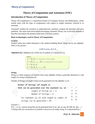
  • 1. Theory of Computation Prof. K. Adisesha 1 Theory of Computation and Automata (TOC) Introduction of Theory of Computation Theory Of Computation is a theoretical branch of Computer Science and Mathematics, which mainly deals with the logic of computation with respect to simple machines, referred to as automata. Automata* enables the scientists to understand how machines compute the functions and solve problems. The main motivation behind developing Automata Theory was to develop methods to describe and analyse the dynamic behaviour of discrete systems. Basic terminologies, used in Theory of Computation: Symbol: Symbol (often also called character) is the smallest building block, which can be any alphabet, letter or any picture. A, B, C, a, b, c, d, 1, 2 Alphabets (Σ): Alphabets are a finite set of symbols. It is denoted by ∑. String: String is a finite sequence of symbols from some alphabet. String is generally denoted as w and length of a string is denoted as |w|. Number of Strings (of length 2) that can be generated over the alphabet {a, b} – Example 1: If ∑ = {a, b}, various string that can be generated from ∑ are {ab, aa, aaa, bb, bbb, ba, aba.....}. A string with zero occurrences of symbols is known as an empty string. It is represented by ε.
  • 2. Theory of Computation Prof. K. Adisesha 2 The number of symbols in a string w is called the length of a string. It is denoted by |w|. Language: A language is a collection of appropriate string. A language which is formed over Σ can be Finite or Infinite. Example: 1 L1 = {Set of string of length 2} = {aa, bb, ba, bb} Finite Language Example: 2 L2 = {Set of all strings starts with 'a'} = {a, aa, aaa, abb, abbb, ababb } Infinite Language A language is a set of strings, chosen from some Σ* or we can say- ‘A language is a subset of Σ*‘. A language which can be formed over ‘ Σ ‘ can be Finite or Infinite. Theory of automata Theory of automata is a theoretical branch of computer science and mathematical. It is the study of abstract machines and the computation problems that can be solved using these machines. The abstract machine is called the automata. An automaton with a finite number of states is called a Finite automaton. Introduction of Finite Automata Finite Automata (FA) is the simplest machine to recognize patterns. The finite automata or finite state machine is an abstract machine which have five elements or tuple. It has a set of states and rules for moving from one state to another but it depends upon the applied input symbol. Basically, it is an abstract model of digital computer. Following figure shows some essential features of a general automation. Figure: Features of Finite Automata
  • 3. Theory of Computation Prof. K. Adisesha 3 The above figure shows following features of automata: 1. Input 2. Output 3. States of automata 4. State relation 5. Output relation A Finite Automata consists of the following: Formal specification of machine is {Q, Σ, q, F, δ}. Q : Finite set of states. Σ : set of Input Symbols. q : Initial state. F : set of Final States. δ : Transition Function. Types of Automata: There are two types of finite automata: ➢ DFA (deterministic finite automata) ➢ NFA (non-deterministic finite automata) 1) Deterministic Finite Automata (DFA) DFA refers to deterministic finite automata. Deterministic refers to the uniqueness of the computation. In the DFA, the machine goes to one state only for a particular input character. DFA does not accept the null move. DFA consists of 5 tuples {Q, Σ, q, F, δ}. Q : set of all states. Σ : set of input symbols. (Symbols which machine takes as input) q : Initial state. (Starting state of a machine) F : set of final state. δ : Transition Function, defined as δ : Q X Σ --> Q. In a DFA, for a particular input character, the machine goes to one state only. A transition function is defined on every state for every input symbol. Also, in DFA null (or ε) move is not allowed, i.e., DFA cannot change state without any input character. For example, below DFA with Σ = {0, 1} accepts all strings ending with 0.
  • 4. Theory of Computation Prof. K. Adisesha 4 Figure: DFA with Σ = {0, 1} One important thing to note is, there can be many possible DFAs for a pattern. A DFA with minimum number of states is generally preferred. 2) Nondeterministic Finite Automata (NFA) NFA stands for non-deterministic finite automata. It is used to transmit any number of states for a particular input. It can accept the null move. NFA is similar to DFA except following additional features: 1. Null (or ε) move is allowed i.e., it can move forward without reading symbols. 2. Ability to transmit to any number of states for a particular input. However, these above features don’t add any power to NFA. If we compare both in terms of power, both are equivalent. Due to above additional features, NFA has a different transition function, rest is same as DFA. δ: Transition Function δ: Q X (Σ U ε ) --> 2 ^ Q. As you can see in transition function is for any input including null (or ε), NFA can go to any state number of states. For example, below is a NFA for above problem Nondeterministic Finite Automata (NFA) One important thing to note is, in NFA, if any path for an input string leads to a final state, then the input string accepted. For example, in above NFA, there are multiple paths for input string “00”. Since, one of the paths leads to a final state, “00” is accepted by above NFA.
  • 5. Theory of Computation Prof. K. Adisesha 5 Some important points about DFA and NFA: ➢ Every DFA is NFA, but NFA is not DFA. ➢ There can be multiple final states in both NFA and DFA. ➢ DFA is used in Lexical Analysis in Compiler. ➢ NFA is more of a theoretical concept. Transition Diagram A transition diagram or state transition diagram is a directed graph which can be constructed as follows: ➢ There is a node for each state in Q, which is represented by the circle. ➢ There is a directed edge from node q to node p labeled a if δ(q, a) = p. ➢ In the start state, there is an arrow with no source. ➢ Accepting states or final states are indicating by a double circle. Some Notations that are used in the transition diagram: There is a description of how a DFA operates: ➢ In DFA, the input to the automata can be any string. Now, put a pointer to the start state q and read the input string w from left to right and move the pointer according to the transition function, δ. We can read one symbol at a time. If the next symbol of string w is a and the pointer is on state p, move the pointer to δ(p, a). When the end of the input string w is encountered, then the pointer is on some state F.
  • 6. Theory of Computation Prof. K. Adisesha 6 ➢ The string w is said to be accepted by the DFA if r ∈ F that means the input string w is processed successfully and the automata reached its final state. The string is said to be rejected by DFA if r ∉ F. Example 1: DFA with ∑ = {0, 1} accepts all strings starting with 1. Solution: The finite automata can be represented using a transition graph. In the above diagram, the machine initially is in start state q0 then on receiving input 1 the machine changes its state to q1. From q0 on receiving 0, the machine changes its state to q2, which is the dead state. From q1 on receiving input 0, 1 the machine changes its state to q1, which is the final state. The possible input strings that can be generated are 10, 11, 110, 101, 111......., that means all string starts with 1. Example 2: NFA with ∑ = {0, 1} accepts all strings starting with 1. Solution: The NFA can be represented using a transition graph. In the above diagram, the machine initially is in start state q0 then on receiving input 1 the machine changes its state to q1. From q1 on receiving input 0, 1 the machine changes its state to q1. The possible input string that can be generated is 10, 11, 110, 101, 111......, that means all string starts with 1. Transition Table The transition table is basically a tabular representation of the transition function. It takes two arguments (a state and a symbol) and returns a state (the "next state").
  • 7. Theory of Computation Prof. K. Adisesha 7 A transition table is represented by the following things: ➢ Columns correspond to input symbols. ➢ Rows correspond to states. ➢ Entries correspond to the next state. ➢ The start state is denoted by an arrow with no source. ➢ The accept state is denoted by a star. Example 1: Solution: Transition table of given DFA is as follows: Present State Next state for Input 0 Next State of Input 1 →q0 q1 q2 q1 q0 q2 *q2 q2 q2 Explanation: ➢ In the above table, the first column indicates all the current states. Under column 0 and 1, the next states are shown. ➢ The first row of the transition table can be read as, when the current state is q0, on input 0 the next state will be q1 and on input 1 the next state will be q2. ➢ In the second row, when the current state is q1, on input 0, the next state will be q0, and on 1 input the next state will be q2. ➢ In the third row, when the current state is q2 on input 0, the next state will be q2, and on 1 input the next state will be q2.
  • 8. Theory of Computation Prof. K. Adisesha 8 ➢ The arrow marked to q0 indicates that it is a start state and circle marked to q2 indicates that it is a final state. Example 2: Solution: Transition table of given NFA is as follows: Explanation: ➢ The first row of the transition table can be read as, when the current state is q0, on input 0 the next state will be q0 and on input 1 the next state will be q1. ➢ In the second row, when the current state is q1, on input 0 the next state will be either q1 or q2, and on 1 input the next state will be q2. ➢ In the third row, when the current state is q2 on input 0, the next state will be q1, and on 1 input the next state will be q3. ➢ In the fourth row, when the current state is q3 on input 0, the next state will be q2, and on 1 input the next state will be q2. DFA (Deterministic finite automata) Present State Next state for Input 0 Next State of Input 1 →q0 q0 q1 q1 q1, q2 q2 q2 q1 q3 *q3 q2 q2
  • 9. Theory of Computation Prof. K. Adisesha 9 ➢ DFA refers to deterministic finite automata. Deterministic refers to the uniqueness of the computation. The finite automata are called deterministic finite automata if the machine is read an input string one symbol at a time. ➢ In DFA, there is only one path for specific input from the current state to the next state. ➢ DFA does not accept the null move, i.e., the DFA cannot change state without any input character. ➢ DFA can contain multiple final states. It is used in Lexical Analysis in Compiler. In the following diagram, we can see that from state q0 for input a, there is only one path which is going to q1. Similarly, from q0, there is only one path for input b going to q2. Formal Definition of DFA A DFA is a collection of 5-tuples same as we described in the definition of FA. Q: finite set of states ∑: finite set of the input symbol q0: initial state F: final state δ: Transition function Transition function can be defined as: δ: Q x ∑→Q Graphical Representation of DFA A DFA can be represented by digraphs called state diagram. In which: ➢ The state is represented by vertices. ➢ The arc labelled with an input character show the transitions. ➢ The initial state is marked with an arrow. ➢ The final state is denoted by a double circle.
  • 10. Theory of Computation Prof. K. Adisesha 10 Example 1: Q = {q0, q1, q2} ∑ = {0, 1} q0 = {q0} F = {q2} Solution: Transition Diagram: Transition Table: Present State Next state for Input 0 Next State of Input 1 →q0 q0 q1 q1 q2 q1 *q2 q2 q2 Example 2: DFA with ∑ = {0, 1} accepts all starting with 0. Solution:
  • 11. Theory of Computation Prof. K. Adisesha 11 Explanation: o In the above diagram, we can see that on given 0 as input to DFA in state q0 the DFA changes state to q1 and always go to final state q1 on starting input 0. It can accept 00, 01, 000, 001.... etc. It can't accept any string which starts with 1, because it will never go to final state on a string starting with 1. Example 3: DFA with ∑ = {0, 1} accepts all ending with 0. Solution: Explanation: In the above diagram, we can see that on given 0 as input to DFA in state q0, the DFA changes state to q1. It can accept any string which ends with 0 like 00, 10, 110, 100....etc. It can't accept any string which ends with 1, because it will never go to the final state q1 on 1 input, so the string ending with 1, will not be accepted or will be rejected. Examples of DFA Example 1: Design a FA with ∑ = {0, 1} accepts those string which starts with 1 and ends with 0. Solution: The FA will have a start state q0 from which only the edge with input 1 will go to the next state.
  • 12. Theory of Computation Prof. K. Adisesha 12 In state q1, if we read 1, we will be in state q1, but if we read 0 at state q1, we will reach to state q2 which is the final state. In state q2, if we read either 0 or 1, we will go to q2 state or q1 state respectively. Note that if the input ends with 0, it will be in the final state. Example 2: Design a FA with ∑ = {0, 1} accepts the only input 101. Solution: In the given solution, we can see that only input 101 will be accepted. Hence, for input 101, there is no other path shown for other input. Example 3: Design FA with ∑ = {0, 1} accepts even number of 0's and even number of 1's. Solution: This FA will consider four different stages for input 0 and input 1. The stages could be: Here q0 is a start state and the final state also. Note carefully that a symmetry of 0's and 1's is maintained. We can associate meanings to each state as:
  • 13. Theory of Computation Prof. K. Adisesha 13 q0: state of even number of 0's and even number of 1's. q1: state of odd number of 0's and even number of 1's. q2: state of odd number of 0's and odd number of 1's. q3: state of even number of 0's and odd number of 1's. Example 4: Design FA with ∑ = {0, 1} accepts the set of all strings with three consecutive 0's. Solution: The strings that will be generated for this particular languages are 000, 0001, 1000, 10001, .... in which 0 always appears in a clump of 3. The transition graph is as follows: Example 5: Design a DFA L(M) = {w | w ε {0, 1}*} and W is a string that does not contain consecutive 1's. Solution: When three consecutive 1's occur the DFA will be: Here two consecutive 1's or single 1 is acceptable, hence The stages q0, q1, q2 are the final states. The DFA will generate the strings that do not contain consecutive 1's like 10, 110, 101,..... etc. Example 6: Design a FA with ∑ = {0, 1} accepts the strings with an even number of 0's followed by single 1.
  • 14. Theory of Computation Prof. K. Adisesha 14 Solution: The DFA can be shown by a transition diagram as: NFA (Non-Deterministic finite automata) o NFA stands for non-deterministic finite automata. It is easy to construct an NFA than DFA for a given regular language. o The finite automata are called NFA when there exist many paths for specific input from the current state to the next state. o Every NFA is not DFA, but each NFA can be translated into DFA. o NFA is defined in the same way as DFA but with the following two exceptions, it contains multiple next states, and it contains ε transition. In the following image, we can see that from state q0 for input a, there are two next states q1 and q2, similarly, from q0 for input b, the next states are q0 and q1. Thus it is not fixed or determined that with a particular input where to go next. Hence this FA is called non-deterministic finite automata. Formal definition of NFA: NFA also has five states same as DFA, but with different transition function, as shown follows: δ: Q x ∑ →2Q
  • 15. Theory of Computation Prof. K. Adisesha 15 where, Q: finite set of states ∑: finite set of the input symbol q0: initial state F: final state δ: Transition function Graphical Representation of an NFA An NFA can be represented by digraphs called state diagram. In which: 1. The state is represented by vertices. 2. The arc labeled with an input character shows the transitions. 3. The initial state is marked with an arrow. 4. The final state is denoted by the double circle. Example 1: Q = {q0, q1, q2} ∑ = {0, 1} q0 = {q0} F = {q2} Solution: Transition diagram: Transition Table: Present State Next state for Input 0 Next State of Input 1 →q0 q0, q1 q1 q1 q2 q0 *q2 q2 q1, q2
  • 16. Theory of Computation Prof. K. Adisesha 16 In the above diagram, we can see that when the current state is q0, on input 0, the next state will be q0 or q1, and on 1 input the next state will be q1. When the current state is q1, on input 0 the next state will be q2 and on 1 input, the next state will be q0. When the current state is q2, on 0 input the next state is q2, and on 1 input the next state will be q1 or q2. Example 2: NFA with ∑ = {0, 1} accepts all strings with 01. Solution: Transition Table: Present State Next state for Input 0 Next State of Input 1 →q0 q1 ε q1 ε q2 *q2 q2 q2 Example 3: NFA with ∑ = {0, 1} and accept all string of length at least 2. Solution: Transition Table: Present State Next state for Input 0 Next State of Input 1 →q0 q1 q1 q1 q2 q2 *q2 ε
  • 17. Theory of Computation Prof. K. Adisesha 17 Examples of NFA Example 1: Design a NFA for the transition table as given below: Present State 0 1 →q0 q0, q1 q0, q2 q1 q3 ε q2 q2, q3 q3 →q3 q3 q3 Solution: The transition diagram can be drawn by using the mapping function as given in the table. Here, δ(q0, 0) = {q0, q1} δ(q0, 1) = {q0, q2} Then, δ(q1, 0) = {q3} Then, δ(q2, 0) = {q2, q3} δ(q2, 1) = {q3} Then, δ(q3, 0) = {q3} δ(q3, 1) = {q3}
  • 18. Theory of Computation Prof. K. Adisesha 18 Example 2: Design an NFA with ∑ = {0, 1} accepts all string ending with 01. Solution: Hence, NFA would be: Example 3: Design an NFA with ∑ = {0, 1} in which double '1' is followed by double '0'. Solution: The FA with double 1 is as follows: It should be immediately followed by double 0. Then, Now before double 1, there can be any string of 0 and 1. Similarly, after double 0, there can be any string of 0 and 1. Hence the NFA becomes:
  • 19. Theory of Computation Prof. K. Adisesha 19 Now considering the string 01100011 q0 → q1 → q2 → q3 → q4 → q4 → q4 → q4 Example 4: Design an NFA in which all the string contain a substring 1110. Solution: The language consists of all the string containing substring 1010. The partial transition diagram can be: Now as 1010 could be the substring. Hence we will add the inputs 0's and 1's so that the substring 1010 of the language can be maintained. Hence the NFA becomes: Transition table for the above transition diagram can be given below: Consider a string 111010, δ(q1, 111010) = δ(q1, 1100) = δ(q1, 100) = δ(q2, 00) Present State 0 1 →q1 q1 q1, q2 q2 q3 q3 q4 q4 q5 *q5 q5 q5
  • 20. Theory of Computation Prof. K. Adisesha 20 Got stuck! As there is no path from q2 for input symbol 0. We can process string 111010 in another way. δ(q1, 111010) = δ(q2, 1100) = δ(q3, 100) = δ(q4, 00) = δ(q5, 0) = δ(q5, ε) As state q5 is the accept state. We get the complete scanned, and we reached to the final state. Example 5: Design an NFA with ∑ = {0, 1} accepts all string in which the third symbol from the right end is always 0. Solution: Thus, we get the third symbol from the right end as '0' always. The NFA can be: The above image is an NFA because in state q0 with input 0, we can either go to state q0 or q1. Eliminating ε Transitions NFA with ε can be converted to NFA without ε, and this NFA without ε can be converted to DFA. To do this, we will use a method, which can remove all the ε transition from given NFA. The method will be: 1. Find out all the ε transitions from each state from Q. That will be called as ε-closure{q1} where qi ∈ Q. 2. Then δ' transitions can be obtained. The δ' transitions mean a ε-closure on δ moves. 3. Repeat Step-2 for each input symbol and each state of given NFA. 4. Using the resultant states, the transition table for equivalent NFA without ε can be built.
  • 21. Theory of Computation Prof. K. Adisesha 21 Example: Convert the following NFA with ε to NFA without ε. Solutions: We will first obtain ε-closures of q0, q1 and q2 as follows: ε-closure(q0) = {q0} ε-closure(q1) = {q1, q2} ε-closure(q2) = {q2} Now the δ' transition on each input symbol is obtained as: δ'(q0, a) = ε-closure(δ(δ^(q0, ε),a)) = ε-closure(δ(ε-closure(q0),a)) = ε-closure(δ(q0, a)) = ε-closure(q1) = {q1, q2} δ'(q0, b) = ε-closure(δ(δ^(q0, ε),b)) = ε-closure(δ(ε-closure(q0),b)) = ε-closure(δ(q0, b)) = Ф Now the δ' transition on q1 is obtained as: δ'(q1, a) = ε-closure(δ(δ^(q1, ε),a)) = ε-closure(δ(ε-closure(q1),a)) = ε-closure(δ(q1, q2), a) = ε-closure(δ(q1, a) ∪ δ(q2, a)) = ε-closure(Ф ∪ Ф) = Ф
  • 22. Theory of Computation Prof. K. Adisesha 22 δ'(q1, b) = ε-closure(δ(δ^(q1, ε),b)) = ε-closure(δ(ε-closure(q1),b)) = ε-closure(δ(q1, q2), b) = ε-closure(δ(q1, b) ∪ δ(q2, b)) = ε-closure(Ф ∪ q2) = {q2} The δ' transition on q2 is obtained as: δ'(q2, a) = ε-closure(δ(δ^(q2, ε),a)) = ε-closure(δ(ε-closure(q2),a)) = ε-closure(δ(q2, a)) = ε-closure(Ф) = Ф δ'(q2, b) = ε-closure(δ(δ^(q2, ε),b)) = ε-closure(δ(ε-closure(q2),b)) = ε-closure(δ(q2, b)) = ε-closure(q2) = {q2} Now we will summarize all the computed δ' transitions: δ'(q0, a) = {q0, q1} δ'(q0, b) = Ф δ'(q1, a) = Ф δ'(q1, b) = {q2} δ'(q2, a) = Ф δ'(q2, b) = {q2} The transition table can be: States a b →q0 {q1, q2} Ф *q1 Ф {q2} *q2 Ф {q2}
  • 23. Theory of Computation Prof. K. Adisesha 23 State q1 and q2 become the final state as ε-closure of q1 and q2 contain the final state q2. The NFA can be shown by the following transition diagram: Conversion from NFA to DFA In this section, we will discuss the method of converting NFA to its equivalent DFA. In NFA, when a specific input is given to the current state, the machine goes to multiple states. It can have zero, one or more than one move on a given input symbol. On the other hand, in DFA, when a specific input is given to the current state, the machine goes to only one state. DFA has only one move on a given input symbol. Let, M = (Q, ∑, δ, q0, F) is an NFA which accepts the language L(M). There should be equivalent DFA denoted by M' = (Q', ∑', q0', δ', F') such that L(M) = L(M'). Steps for converting NFA to DFA: Step 1: Initially Q' = ϕ Step 2: Add q0 of NFA to Q'. Then find the transitions from this start state. Step 3: In Q', find the possible set of states for each input symbol. If this set of states is not in Q', then add it to Q'. Step 4: In DFA, the final state will be all the states which contain F(final states of NFA) Example 1: Convert the given NFA to DFA. Solution: For the given transition diagram we will first construct the transition table.
  • 24. Theory of Computation Prof. K. Adisesha 24 State 0 1 →q0 q0 q1 q1 {q1, q2} q1 *q2 q2 {q1, q2} Now we will obtain δ' transition for state q0. δ'([q0], 0) = [q0] δ'([q0], 1) = [q1] The δ' transition for state q1 is obtained as: δ'([q1], 0) = [q1, q2] (new state generated) δ'([q1], 1) = [q1] The δ' transition for state q2 is obtained as: δ'([q2], 0) = [q2] δ'([q2], 1) = [q1, q2] Now we will obtain δ' transition on [q1, q2]. δ'([q1, q2], 0) = δ(q1, 0) ∪ δ(q2, 0) = {q1, q2} ∪ {q2} = [q1, q2] δ'([q1, q2], 1) = δ(q1, 1) ∪ δ(q2, 1) = {q1} ∪ {q1, q2} = {q1, q2} = [q1, q2] The state [q1, q2] is the final state as well because it contains a final state q2. The transition table for the constructed DFA will be: State 0 1 →[q0] [q0] [q1] [q1] [q1, q2] [q1] *[q2] [q2] [q1, q2] *[q1, q2] [q1, q2] [q1, q2]
  • 25. Theory of Computation Prof. K. Adisesha 25 The Transition diagram will be: The state q2 can be eliminated because q2 is an unreachable state. Example 2: Convert the given NFA to DFA. Solution: For the given transition diagram we will first construct the transition table. State 0 1 →q0 {q0, q1} {q1} *q1 ϕ {q0, q1} Now we will obtain δ' transition for state q0. δ'([q0], 0) = {q0, q1} = [q0, q1] (new state generated) δ'([q0], 1) = {q1} = [q1] The δ' transition for state q1 is obtained as: δ'([q1], 0) = ϕ δ'([q1], 1) = [q0, q1]
  • 26. Theory of Computation Prof. K. Adisesha 26 Now we will obtain δ' transition on [q0, q1]. δ'([q0, q1], 0) = δ(q0, 0) ∪ δ(q1, 0) = {q0, q1} ∪ ϕ = {q0, q1} = [q0, q1] Similarly, δ'([q0, q1], 1) = δ(q0, 1) ∪ δ(q1, 1) = {q1} ∪ {q0, q1} = {q0, q1} = [q0, q1] As in the given NFA, q1 is a final state, then in DFA wherever, q1 exists that state becomes a final state. Hence in the DFA, final states are [q1] and [q0, q1]. Therefore set of final states F = {[q1], [q0, q1]}. The transition table for the constructed DFA will be: State 0 1 →[q0] [q0, q1] [q1] *[q1] ϕ [q0, q1] *[q0, q1] [q0, q1] [q0, q1] The Transition diagram will be:
  • 27. Theory of Computation Prof. K. Adisesha 27 Even we can change the name of the states of DFA. Suppose A = [q0] B = [q1] C = [q0, q1] With these new names the DFA will be as follows: Conversion from NFA with ε to DFA Non-deterministic finite automata(NFA) is a finite automata where for some cases when a specific input is given to the current state, the machine goes to multiple states or more than 1 states. It can contain ε move. It can be represented as M = { Q, ∑, δ, q0, F}. Where: Q: finite set of states ∑: finite set of the input symbol q0: initial state F: final state δ: Transition function NFA with ∈ move: If any FA contains ε transaction or move, the finite automata is called NFA with ∈ move. ε-closure: ε-closure for a given state A means a set of states which can be reached from the state A with only ε(null) move including the state A itself. Steps for converting NFA with ε to DFA: Step 1: We will take the ε-closure for the starting state of NFA as a starting state of DFA.
  • 28. Theory of Computation Prof. K. Adisesha 28 Step 2: Find the states for each input symbol that can be traversed from the present. That means the union of transition value and their closures for each state of NFA present in the current state of DFA. Step 3: If we found a new state, take it as current state and repeat step 2. Step 4: Repeat Step 2 and Step 3 until there is no new state present in the transition table of DFA. Step 5: Mark the states of DFA as a final state which contains the final state of NFA. Example 1: Convert the NFA with ε into its equivalent DFA. Solution: Let us obtain ε-closure of each state. ε-closure {q0} = {q0, q1, q2} ε-closure {q1} = {q1} ε-closure {q2} = {q2} ε-closure {q3} = {q3} ε-closure {q4} = {q4} Now, let ε-closure {q0} = {q0, q1, q2} be state A. Hence δ'(A, 0) = ε-closure {δ((q0, q1, q2), 0) } = ε-closure {δ(q0, 0) ∪ δ(q1, 0) ∪ δ(q2, 0) } = ε-closure {q3} = {q3} call it as state B.
  • 29. Theory of Computation Prof. K. Adisesha 29 δ'(A, 1) = ε-closure {δ((q0, q1, q2), 1) } = ε-closure {δ((q0, 1) ∪ δ(q1, 1) ∪ δ(q2, 1) } = ε-closure {q3} = {q3} = B. The partial DFA will be Now, δ'(B, 0) = ε-closure {δ(q3, 0) } = ϕ δ'(B, 1) = ε-closure {δ(q3, 1) } = ε-closure {q4} = {q4} i.e. state C For state C: δ'(C, 0) = ε-closure {δ(q4, 0) } = ϕ δ'(C, 1) = ε-closure {δ(q4, 1) } = ϕ The DFA will be, Example 2: Convert the given NFA into its equivalent DFA.
  • 30. Theory of Computation Prof. K. Adisesha 30 Solution: Let us obtain the ε-closure of each state. ε-closure(q0) = {q0, q1, q2} ε-closure(q1) = {q1, q2} ε-closure(q2) = {q2} Now we will obtain δ' transition. Let ε-closure(q0) = {q0, q1, q2} call it as state A. δ'(A, 0) = ε-closure{δ((q0, q1, q2), 0)} = ε-closure{δ(q0, 0) ∪ δ(q1, 0) ∪ δ(q2, 0)} = ε-closure{q0} = {q0, q1, q2} δ'(A, 1) = ε-closure{δ((q0, q1, q2), 1)} = ε-closure{δ(q0, 1) ∪ δ(q1, 1) ∪ δ(q2, 1)} = ε-closure{q1} = {q1, q2} call it as state B δ'(A, 2) = ε-closure{δ((q0, q1, q2), 2)} = ε-closure{δ(q0, 2) ∪ δ(q1, 2) ∪ δ(q2, 2)} = ε-closure{q2} = {q2} call it state C Thus we have obtained δ'(A, 0) = A δ'(A, 1) = B δ'(A, 2) = C The partial DFA will be: Now we will find the transitions on states B and C for each input.
  • 31. Theory of Computation Prof. K. Adisesha 31 Hence δ'(B, 0) = ε-closure{δ((q1, q2), 0)} = ε-closure{δ(q1, 0) ∪ δ(q2, 0)} = ε-closure{ϕ} = ϕ δ'(B, 1) = ε-closure{δ((q1, q2), 1)} = ε-closure{δ(q1, 1) ∪ δ(q2, 1)} = ε-closure{q1} = {q1, q2} i.e. state B itself δ'(B, 2) = ε-closure{δ((q1, q2), 2)} = ε-closure{δ(q1, 2) ∪ δ(q2, 2)} = ε-closure{q2} = {q2} i.e. state C itself Thus we have obtained δ'(B, 0) = ϕ δ'(B, 1) = B δ'(B, 2) = C The partial transition diagram will be Now we will obtain transitions for C: δ'(C, 0) = ε-closure{δ(q2, 0)} = ε-closure{ϕ} = ϕ δ'(C, 1) = ε-closure{δ(q2, 1)} = ε-closure{ϕ} = ϕ
  • 32. Theory of Computation Prof. K. Adisesha 32 δ'(C, 2) = ε-closure{δ(q2, 2)} = {q2} Hence the DFA is As A = {q0, q1, q2} in which final state q2 lies hence A is final state. B = {q1, q2} in which the state q2 lies hence B is also final state. C = {q2}, the state q2 lies hence C is also a final state. Minimization of DFA Minimization of DFA means reducing the number of states from given FA. Thus, we get the FSM(finite state machine) with redundant states after minimizing the FSM. We have to follow the various steps to minimize the DFA. These are as follows: Step 1: Remove all the states that are unreachable from the initial state via any set of the transition of DFA. Step 2: Draw the transition table for all pair of states. Step 3: Now split the transition table into two tables T1 and T2. T1 contains all final states, and T2 contains non-final states. Step 4: Find similar rows from T1 such that: 1. δ (q, a) = p 2. δ (r, a) = p That means, find the two states which have the same value of a and b and remove one of them. Step 5: Repeat step 3 until we find no similar rows available in the transition table T1. Step 6: Repeat step 3 and step 4 for table T2 also.
  • 33. Theory of Computation Prof. K. Adisesha 33 Step 7: Now combine the reduced T1 and T2 tables. The combined transition table is the transition table of minimized DFA. Example: Solution: Step 1: In the given DFA, q2 and q4 are the unreachable states so remove them. Step 2: Draw the transition table for the rest of the states. State 0 1 →q0 q1 q3 q1 q0 q3 *q3 q5 q5 *q5 q5 q5 Step 3: Now divide rows of transition table into two sets as: 1. One set contains those rows, which start from non-final states: State 0 1 q0 q1 q3 q1 q0 q3 2. Another set contains those rows, which starts from final states. State 0 1
  • 34. Theory of Computation Prof. K. Adisesha 34 q3 q5 q5 q5 q5 q5 Step 4: Set 1 has no similar rows so set 1 will be the same. Step 5: In set 2, row 1 and row 2 are similar since q3 and q5 transit to the same state on 0 and 1. So skip q5 and then replace q5 by q3 in the rest. State 0 1 q3 q3 q3 Step 6: Now combine set 1 and set 2 as: State 0 1 →q0 q1 q3 q1 q0 q3 *q3 q3 q3 Now it is the transition table of minimized DFA.
  • 35. Theory of Computation Prof. K. Adisesha 35 Unit -2 Regular Expression Regular Expression ➢ The language accepted by finite automata can be easily described by simple expressions called Regular Expressions. It is the most effective way to represent any language. ➢ The languages accepted by some regular expression are referred to as Regular languages. ➢ A regular expression can also be described as a sequence of pattern that defines a string. ➢ Regular expressions are used to match character combinations in strings. String searching algorithm used this pattern to find the operations on a string. For instance: In a regular expression, x* means zero or more occurrence of x. It can generate {e, x, xx, xxx, xxxx, .....} In a regular expression, x+ means one or more occurrence of x. It can generate {x, xx, xxx, xxxx, .....} Operations on Regular Language The various operations on regular language are: ➢ Union: If L and M are two regular languages then their union L U M is also a union. o L U M = {s | s is in L or s is in M} ➢ Intersection: If L and M are two regular languages then their intersection is also an intersection. o L ⋂ M = {st | s is in L and t is in M} ➢ Kleen closure: If L is a regular language then its Kleen closure L1* will also be a regular language. o L* = Zero or more occurrence of language L. Example 1: Write the regular expression for the language accepting all combinations of a's, over the set ∑ = {a} Solution: All combinations of a's means a may be zero, single, double and so on. If a is appearing zero times, that means a null string. That is we expect the set of {ε, a, aa, aaa, ....}. So we give a regular expression for this as: R = a* That is Kleen closure of a.
  • 36. Theory of Computation Prof. K. Adisesha 36 Example 2: Write the regular expression for the language accepting all combinations of a's except the null string, over the set ∑ = {a} Solution: The regular expression has to be built for the language L = {a, aa, aaa, ....} This set indicates that there is no null string. So we can denote regular expression as: R = a+ Example 3: Write the regular expression for the language accepting all the string containing any number of a's and b's. Solution: The regular expression will be: r.e. = (a + b)* This will give the set as L = {ε, a, aa, b, bb, ab, ba, aba, bab, .....}, any combination of a and b. The (a + b)* shows any combination with a and b even a null string. Examples of Regular Expression Example 1: Write the regular expression for the language accepting all the string which are starting with 1 and ending with 0, over ∑ = {0, 1}. Solution: In a regular expression, the first symbol should be 1, and the last symbol should be 0. The r.e. is as follows: R = 1 (0+1)* 0
  • 37. Theory of Computation Prof. K. Adisesha 37 Example 2: Write the regular expression for the language starting and ending with a and having any having any combination of b's in between. Solution: The regular expression will be: R = a b* b Example 3: Write the regular expression for the language starting with a but not having consecutive b's. Solution: The regular expression has to be built for the language: L = {a, aba, aab, aba, aaa, abab, .....} The regular expression for the above language is: R = {a + ab}* Example 4: Write the regular expression for the language accepting all the string in which any number of a's is followed by any number of b's is followed by any number of c's. Solution: As we know, any number of a's means a* any number of b's means b*, any number of c's means c*. Since as given in problem statement, b's appear after a's and c's appear after b's. So the regular expression could be: R = a* b* c* Example 5: Write the regular expression for the language over ∑ = {0} having even length of the string. Solution: The regular expression has to be built for the language: L = {ε, 00, 0000, 000000, ......} The regular expression for the above language is:
  • 38. Theory of Computation Prof. K. Adisesha 38 R = (00)* Example 6: Write the regular expression for the language having a string which should have atleast one 0 and alteast one 1. Solution: The regular expression will be: R = [(0 + 1)* 0 (0 + 1)* 1 (0 + 1)*] + [(0 + 1)* 1 (0 + 1)* 0 (0 + 1)*] Example 7: Describe the language denoted by following regular expression r.e. = (b* (aaa)* b*)* Solution: The language can be predicted from the regular expression by finding the meaning of it. We will first split the regular expression as: r.e. = (any combination of b's) (aaa)* (any combination of b's) L = {The language consists of the string in which a's appear triples, there is no restriction on the number of b's} Example 8: Write the regular expression for the language L over ∑ = {0, 1} such that all the string do not contain the substring 01. Solution: The Language is as follows: L = {ε, 0, 1, 00, 11, 10, 100, .....} The regular expression for the above language is as follows: R = (1* 0*) Example 9:
  • 39. Theory of Computation Prof. K. Adisesha 39 Write the regular expression for the language containing the string over {0, 1} in which there are at least two occurrences of 1's between any two occurrences of 1's between any two occurrences of 0's. Solution: At least two 1's between two occurrences of 0's can be denoted by (0111*0)*. Similarly, if there is no occurrence of 0's, then any number of 1's are also allowed. Hence the r.e. for required language is: R = (1 + (0111*0))* Example 10: Write the regular expression for the language containing the string in which every 0 is immediately followed by 11. Solution: The regular expectation will be: R = (011 + 1)* Conversion of Regular Expression to FA To convert the RE to FA, we are going to use a method called the subset method. This method is used to obtain FA from the given regular expression. This method is given below: Step 1: Design a transition diagram for given regular expression, using NFA with ε moves. Step 2: Convert this NFA with ε to NFA without ε. Step 3: Convert the obtained NFA to equivalent DFA. Example 1: Design a FA from given regular expression 10 + (0 + 11)0* 1. Solution: First we will construct the transition diagram for a given regular expression. Step 1: Step 2:
  • 40. Theory of Computation Prof. K. Adisesha 40 Step 3: Step 4: Step 5: Now we have got NFA without ε. Now we will convert it into required DFA for that, we will first write a transition table for this NFA. State 0 1 →q0 q3 {q1, q2}
  • 41. Theory of Computation Prof. K. Adisesha 41 q1 qf ϕ q2 ϕ q3 q3 q3 qf *qf ϕ ϕ The equivalent DFA will be: State 0 1 →[q0] [q3] [q1, q2] [q1] [qf] ϕ [q2] ϕ [q3] [q3] [q3] [qf] [q1, q2] [qf] [qf] *[qf] ϕ ϕ Example 2: Design a NFA from given regular expression 1 (1* 01* 01*)*. Solution: The NFA for the given regular expression is as follows: Step 1: Step 2: Step 3: Example 3:
  • 42. Theory of Computation Prof. K. Adisesha 42 Construct the FA for regular expression 0*1 + 10. Solution: We will first construct FA for R = 0*1 + 10 as follows: Step 1: Step 2: Step 3: Step 4: Arden's Theorem The Arden's Theorem is useful for checking the equivalence of two regular expressions as well as in the conversion of DFA to a regular expression. Let us see its use in the conversion of DFA to a regular expression.
  • 43. Theory of Computation Prof. K. Adisesha 43 Following algorithm is used to build the regular expression form given DFA. 1. Let q1 be the initial state. 2. There are q2, q3, q4 ....qn number of states. The final state may be some qj where j<= n. 3. Let αji represents the transition from qj to qi. 4. Calculate qi such that qi = αji * qj If qj is a start state then we have: qi = αji * qj + ε 5. Similarly, compute the final state which ultimately gives the regular expression 'r'. Example: Construct the regular expression for the given DFA Solution: Let us write down the equations q1 = q1 0 + ε Since q1 is the start state, so ε will be added, and the input 0 is coming to q1 from q1 hence we write State = source state of input × input coming to it Similarly, q2 = q1 1 + q2 1 q3 = q2 0 + q3 (0+1) Since the final states are q1 and q2, we are interested in solving q1 and q2 only. Let us see q1 first q1 = q1 0 + ε We can re-write it as q1 = ε + q1 0 Which is similar to R = Q + RP, and gets reduced to R = OP*. Assuming R = q1, Q = ε, P = 0 We get
  • 44. Theory of Computation Prof. K. Adisesha 44 q1 = ε.(0)* q1 = 0* (ε.R*= R*) Substituting the value into q2, we will get q2 = 0* 1 + q2 1 q2 = 0* 1 (1) * (R = Q + RP → Q P*) The regular expression is given by r = q1 + q2 = 0* + 0* 1.1* r = 0* + 0* 1+ (1.1* = 1+) Moore Machine Moore machine is a finite state machine in which the next state is decided by the current state and current input symbol. The output symbol at a given time depends only on the present state of the machine. Moore machine can be described by 6 tuples (Q, q0, ∑, O, δ, λ) where, Q: finite set of states q0: initial state of machine ∑: finite set of input symbols O: output alphabet δ: transition function where Q × ∑ → Q λ: output function where Q → O Example 1: The state diagram for Moore Machine is
  • 45. Theory of Computation Prof. K. Adisesha 45 Transition table for Moore Machine is: In the above Moore machine, the output is represented with each input state separated by /. The output length for a Moore machine is greater than input by 1. Input: 010 Transition: δ (q0,0) => δ(q1,1) => δ(q1,0) => q2 Output: 1110(1 for q0, 1 for q1, again 1 for q1, 0 for q2) Example 2: Design a Moore machine to generate 1's complement of a given binary number. Solution: To generate 1's complement of a given binary number the simple logic is that if the input is 0 then the output will be 1 and if the input is 1 then the output will be 0. That means there are three states. One state is start state. The second state is for taking 0's as input and produces output as 1. The third state is for taking 1's as input and producing output as 0. Hence the Moore machine will be, For instance, take one binary number 1011 then Input 1 0 1 1 State q0 q2 q1 q2 q2 Output 0 0 1 0 0
  • 46. Theory of Computation Prof. K. Adisesha 46 Thus we get 00100 as 1's complement of 1011, we can neglect the initial 0 and the output which we get is 0100 which is 1's complement of 1011. The transaction table is as follows: Thus Moore machine M = (Q, q0, ∑, O, δ, λ); where Q = {q0, q1, q2}, ∑ = {0, 1}, O = {0, 1}. the transition table shows the δ and λ functions. Example 3: Design a Moore machine for a binary input sequence such that if it has a substring 101, the machine output A, if the input has substring 110, it outputs B otherwise it outputs C. Solution: For designing such a machine, we will check two conditions, and those are 101 and 110. If we get 101, the output will be A, and if we recognize 110, the output will be B. For other strings, the output will be C. The partial diagram will be: Now we will insert the possibilities of 0's and 1's for each state. Thus the Moore machine becomes:
  • 47. Theory of Computation Prof. K. Adisesha 47 Example 4: Construct a Moore machine that determines whether an input string contains an even or odd number of 1's. The machine should give 1 as output if an even number of 1's are in the string and 0 otherwise. Solution: The Moore machine will be: This is the required Moore machine. In this machine, state q1 accepts an odd number of 1's and state q0 accepts even number of 1's. There is no restriction on a number of zeros. Hence for 0 input, self-loop can be applied on both the states. Example 5: Design a Moore machine with the input alphabet {0, 1} and output alphabet {Y, N} which produces Y as output if input sequence contains 1010 as a substring otherwise, it produces N as output. Solution: The Moore machine will be:
  • 48. Theory of Computation Prof. K. Adisesha 48 Conversion from Mealy machine to Moore Machine In Moore machine, the output is associated with every state, and in Mealy machine, the output is given along the edge with input symbol. To convert Moore machine to Mealy machine, state output symbols are distributed to input symbol paths. But while converting the Mealy machine to Moore machine, we will create a separate state for every new output symbol and according to incoming and outgoing edges are distributed. The following steps are used for converting Mealy machine to the Moore machine: Step 1: For each state(Qi), calculate the number of different outputs that are available in the transition table of the Mealy machine. Step 2: Copy state Qi, if all the outputs of Qi are the same. Break qi into n states as Qin, if it has n distinct outputs where n = 0, 1, 2.... Step 3: If the output of initial state is 0, insert a new initial state at the starting which gives 1 output. Example 1: Convert the following Mealy machine into equivalent Moore machine. Solution: Transition table for above Mealy machine is as follows:
  • 49. Theory of Computation Prof. K. Adisesha 49 ➢ For state q1, there is only one incident edge with output 0. So, we don't need to split this state in Moore machine. ➢ For state q2, there is 2 incident edge with output 0 and 1. So, we will split this state into two states q20( state with output 0) and q21(with output 1). ➢ For state q3, there is 2 incident edge with output 0 and 1. So, we will split this state into two states q30( state with output 0) and q31( state with output 1). ➢ For state q4, there is only one incident edge with output 0. So, we don't need to split this state in Moore machine. Transition table for Moore machine will be: Transition diagram for Moore machine will be:
  • 50. Theory of Computation Prof. K. Adisesha 50 Example 2: Convert the following Mealy machine into equivalent Moore machine. Solution: Transition table for above Mealy machine is as follows: The state q1 has only one output. The state q2 and q3 have both output 0 and 1. So we will create two states for these states. For q2, two states will be q20(with output 0) and q21(with output 1). Similarly, for q3 two states will be q30(with output 0) and q31(with output 1). Transition table for Moore machine will be:
  • 51. Theory of Computation Prof. K. Adisesha 51 Transition diagram for Moore machine will be: Conversion from Moore machine to Mealy Machine In the Moore machine, the output is associated with every state, and in the mealy machine, the output is given along the edge with input symbol. The equivalence of the Moore machine and Mealy machine means both the machines generate the same output string for same input string. We cannot directly convert Moore machine to its equivalent Mealy machine because the length of the Moore machine is one longer than the Mealy machine for the given input. To convert Moore machine to Mealy machine, state output symbols are distributed into input symbol paths. We are going to use the following method to convert the Moore machine to Mealy machine. Method for conversion of Moore machine to Mealy machine Let M = (Q, ∑, δ, λ, q0) be a Moore machine. The equivalent Mealy machine can be represented by M' = (Q, ∑, δ, λ', q0). The output function λ' can be obtained as: λ' (q, a) = λ(δ(q, a))
  • 52. Theory of Computation Prof. K. Adisesha 52 Example 1: Convert the following Moore machine into its equivalent Mealy machine. Solution: The transition table of given Moore machine is as follows: Q a b Output(λ) q0 q0 q1 0 q1 q0 q1 1 The equivalent Mealy machine can be obtained as follows: λ' (q0, a) = λ(δ(q0, a)) = λ(q0) = 0 λ' (q0, b) = λ(δ(q0, b)) = λ(q1) = 1 The λ for state q1 is as follows: λ' (q1, a) = λ(δ(q1, a)) = λ(q0) = 0 λ' (q1, b) = λ(δ(q1, b)) = λ(q1) = 1 Hence the transition table for the Mealy machine can be drawn as follows:
  • 53. Theory of Computation Prof. K. Adisesha 53 The equivalent Mealy machine will be, Example 2: Convert the given Moore machine into its equivalent Mealy machine. Solution: The transition table of given Moore machine is as follows: Q a b Output(λ) q0 q1 q0 0 q1 q1 q2 0 q2 q1 q0 1 The equivalent Mealy machine can be obtained as follows: λ' (q0, a) = λ(δ(q0, a)) = λ(q1) = 0 λ' (q0, b) = λ(δ(q0, b)) = λ(q0) = 0 The λ for state q1 is as follows:
  • 54. Theory of Computation Prof. K. Adisesha 54 λ' (q1, a) = λ(δ(q1, a)) = λ(q1) = 0 λ' (q1, b) = λ(δ(q1, b)) = λ(q2) = 1 The λ for state q2 is as follows: λ' (q2, a) = λ(δ(q2, a)) = λ(q1) = 0 λ' (q2, b) = λ(δ(q2, b)) = λ(q0) = 0 Hence the transition table for the Mealy machine can be drawn as follows: The equivalent Mealy machine will be, Example 3: Convert the given Moore machine into its equivalent Mealy machine. Q a b Output(λ) q0 q0 q1 0
  • 55. Theory of Computation Prof. K. Adisesha 55 q1 q2 q0 1 q2 q1 q2 2 Solution: The transaction diagram for the given problem can be drawn as: The equivalent Mealy machine can be obtained as follows: λ' (q0, a) = λ(δ(q0, a)) = λ(q0) = 0 λ' (q0, b) = λ(δ(q0, b)) = λ(q1) = 1 The λ for state q1 is as follows: λ' (q1, a) = λ(δ(q1, a)) = λ(q2) = 2 λ' (q1, b) = λ(δ(q1, b)) = λ(q0) = 0 The λ for state q2 is as follows: λ' (q2, a) = λ(δ(q2, a)) = λ(q1) = 1 λ' (q2, b) = λ(δ(q2, b)) = λ(q2) = 2 Hence the transition table for the Mealy machine can be drawn as follows:
  • 56. Theory of Computation Prof. K. Adisesha 56 The equivalent Mealy machine will be,
  • 57. Theory of Computation Prof. K. Adisesha 57 Unit -3 Context-Free Grammar (CFG) CFG stands for context-free grammar. It is is a formal grammar which is used to generate all possible patterns of strings in a given formal language. Context-free grammar G can be defined by four tuples as: G = (V, T, P, S) Where, ➢ G is the grammar, which consists of a set of the production rule. It is used to generate the string of a language. ➢ T is the final set of a terminal symbol. It is denoted by lower case letters. ➢ V is the final set of a non-terminal symbol. It is denoted by capital letters. ➢ P is a set of production rules, which is used for replacing non-terminals symbols(on the left side of the production) in a string with other terminal or non-terminal symbols(on the right side of the production). ➢ S is the start symbol which is used to derive the string. We can derive the string by repeatedly replacing a non-terminal by the right-hand side of the production until all non- terminal have been replaced by terminal symbols. Example 1: Construct the CFG for the language having any number of a's over the set ∑= {a}. Solution: As we know the regular expression for the above language is r.e. = a* Production rule for the Regular expression is as follows: S → aS rule 1 S → ε rule 2 Now if we want to derive a string "aaaaaa", we can start with start symbols. S aS aaS rule 1 aaaS rule 1 aaaaS rule 1 aaaaaS rule 1
  • 58. Theory of Computation Prof. K. Adisesha 58 aaaaaaS rule 1 aaaaaaε rule 2 aaaaaa The r.e. = a* can generate a set of string {ε, a, aa, aaa,.....}. We can have a null string because S is a start symbol and rule 2 gives S → ε. Example 2: Construct a CFG for the regular expression (0+1)* Solution: The CFG can be given by, Production rule (P): S → 0S | 1S S → ε The rules are in the combination of 0's and 1's with the start symbol. Since (0+1)* indicates {ε, 0, 1, 01, 10, 00, 11, ....}. In this set, ε is a string, so in the rule, we can set the rule S → ε. Example 3: Construct a CFG for a language L = {wcwR | where w € (a, b)*}. Solution: The string that can be generated for a given language is {aacaa, bcb, abcba, bacab, abbcbba, ....} The grammar could be: S → aSa rule 1 S → bSb rule 2 S → c rule 3 Now if we want to derive a string "abbcbba", we can start with start symbols. S → aSa S → abSba from rule 2 S → abbSbba from rule 2 S → abbcbba from rule 3 Thus any of this kind of string can be derived from the given production rules.
  • 59. Theory of Computation Prof. K. Adisesha 59 Example 4: Construct a CFG for the language L = an b2n where n>=1. Solution: The string that can be generated for a given language is {abb, aabbbb, aaabbbbbb....}. The grammar could be: S → aSbb | abb Now if we want to derive a string "aabbbb", we can start with start symbols. S → aSbb S → aabbbb Derivation Derivation is a sequence of production rules. It is used to get the input string through these production rules. During parsing, we have to take two decisions. These are as follows: o We have to decide the non-terminal which is to be replaced. o We have to decide the production rule by which the non-terminal will be replaced. We have two options to decide which non-terminal to be placed with production rule. 1. Leftmost Derivation: In the leftmost derivation, the input is scanned and replaced with the production rule from left to right. So in leftmost derivation, we read the input string from left to right. Example: Production rules: E = E + E E = E - E E = a | b Input a - b + a The leftmost derivation is: E = E + E E = E - E + E
  • 60. Theory of Computation Prof. K. Adisesha 60 E = a - E + E E = a - b + E E = a - b + a 2. Rightmost Derivation: In rightmost derivation, the input is scanned and replaced with the production rule from right to left. So in rightmost derivation, we read the input string from right to left. Example Production rules: E = E + E E = E - E E = a | b Input a - b + a The rightmost derivation is: E = E - E E = E - E + E E = E - E + a E = E - b + a E = a - b + a When we use the leftmost derivation or rightmost derivation, we may get the same string. This type of derivation does not affect on getting of a string. Examples of Derivation: Example 1: Derive the string "abb" for leftmost derivation and rightmost derivation using a CFG given by, S → AB | ε A → aB B → Sb Solution: Leftmost derivation:
  • 61. Theory of Computation Prof. K. Adisesha 61 Rightmost derivation: Example 2: Derive the string "aabbabba" for leftmost derivation and rightmost derivation using a CFG given by, 1. S → aB | bA 2. S → a | aS | bAA 3. S → b | aS | aBB Solution: Leftmost derivation: S aB S → aB aaBB B → aBB aabB B → b
  • 62. Theory of Computation Prof. K. Adisesha 62 aabbS B → bS aabbaB S → aB aabbabS B → bS aabbabbA S → bA aabbabba A → a Rightmost derivation: S aB S → aB aaBB B → aBB aaBbS B → bS aaBbbA S → bA aaBbba A → a aabSbba B → bS aabbAbba S → bA aabbabba A → a Example 3: Derive the string "00101" for leftmost derivation and rightmost derivation using a CFG given by, S → A1B A → 0A | ε B → 0B | 1B | ε Solution: Leftmost derivation: S A1B 0A1B 00A1B 001B 0010B 00101B 00101 Rightmost derivation:
  • 63. Theory of Computation Prof. K. Adisesha 63 S A1B A10B A101B A101 0A101 00A101 00101 Ambiguity in Grammar A grammar is said to be ambiguous if there exists more than one leftmost derivation or more than one rightmost derivation or more than one parse tree for the given input string. If the grammar is not ambiguous, then it is called unambiguous. If the grammar has ambiguity, then it is not good for compiler construction. No method can automatically detect and remove the ambiguity, but we can remove ambiguity by re-writing the whole grammar without ambiguity. Example 1: Let us consider a grammar G with the production rule E → I E → E + E E → E * E
  • 64. Theory of Computation Prof. K. Adisesha 64 E → (E) I → ε | 0 | 1 | 2 | ... | 9 Solution: For the string "3 * 2 + 5", the above grammar can generate two parse trees by leftmost derivation: Since there are two parse trees for a single string "3 * 2 + 5", the grammar G is ambiguous. Example 2: Check whether the given grammar G is ambiguous or not. E → E + E E → E - E E → id Solution: From the above grammar String "id + id - id" can be derived in 2 ways: First Leftmost derivation E → E + E → id + E → id + E - E → id + id - E → id + id- id Second Leftmost derivation E → E - E → E + E - E → id + E - E → id + id - E → id + id - id Since there are two leftmost derivation for a single string "id + id - id", the grammar G is ambiguous.
  • 65. Theory of Computation Prof. K. Adisesha 65 Example 3: Check whether the given grammar G is ambiguous or not. S → aSb | SS S → ε Solution: For the string "aabb" the above grammar can generate two parse trees Since there are two parse trees for a single string "aabb", the grammar G is ambiguous. Example 4: Check whether the given grammar G is ambiguous or not. A → AA A → (A) A → a Solution: For the string "a(a)aa" the above grammar can generate two parse trees:
  • 66. Theory of Computation Prof. K. Adisesha 66 Since there are two parse trees for a single string "a(a)aa", the grammar G is ambiguous. Unambiguous Grammar A grammar can be unambiguous if the grammar does not contain ambiguity that means if it does not contain more than one leftmost derivation or more than one rightmost derivation or more than one parse tree for the given input string. To convert ambiguous grammar to unambiguous grammar, we will apply the following rules: 1. If the left associative operators (+, -, *, /) are used in the production rule, then apply left recursion in the production rule. Left recursion means that the leftmost symbol on the right side is the same as the non-terminal on the left side. For example, X → Xa 2. If the right associative operates(^) is used in the production rule then apply right recursion in the production rule. Right recursion means that the rightmost symbol on the left side is the same as the non-terminal on the right side. For example, X → aX Example 1: Consider a grammar G is given as follows: S → AB | aaB A → a | Aa B → b Determine whether the grammar G is ambiguous or not. If G is ambiguous, construct an unambiguous grammar equivalent to G. Solution: Let us derive the string "aab" As there are two different parse tree for deriving the same string, the given grammar is ambiguous. Unambiguous grammar will be: S → AB A → Aa | a
  • 67. Theory of Computation Prof. K. Adisesha 67 B → b Example 2: Show that the given grammar is ambiguous. Also, find an equivalent unambiguous grammar. S → ABA A → aA | ε B → bB | ε Solution: The given grammar is ambiguous because we can derive two different parse tree for string aa. The unambiguous grammar is: S → aXY | bYZ | ε Z → aZ | a X → aXY | a | ε Y → bYZ | b | ε Example 3: Show that the given grammar is ambiguous. Also, find an equivalent unambiguous grammar. E → E + E E → E * E E → id Solution: Let us derive the string "id + id * id"
  • 68. Theory of Computation Prof. K. Adisesha 68 As there are two different parse tree for deriving the same string, the given grammar is ambiguous. Unambiguous grammar will be: E → E + T E → T T → T * F T → F F → id Example 4: Check that the given grammar is ambiguous or not. Also, find an equivalent unambiguous grammar. S → S + S S → S * S S → S ^ S S → a Solution: The given grammar is ambiguous because the derivation of string aab can be represented by the following string:
  • 69. Theory of Computation Prof. K. Adisesha 69 Unambiguous grammar will be: S → S + A | A → A * B | B B → C ^ B | C C → a Simplification of CFG As we have seen, various languages can efficiently be represented by a context-free grammar. All the grammar are not always optimized that means the grammar may consist of some extra symbols(non-terminal). Having extra symbols, unnecessary increase the length of grammar. Simplification of grammar means reduction of grammar by removing useless symbols. The properties of reduced grammar are given below: 1. Each variable (i.e. non-terminal) and each terminal of G appears in the derivation of some word in L. 2. There should not be any production as X → Y where X and Y are non-terminal. 3. If ε is not in the language L then there need not to be the production X → ε. Let us study the reduction process in detail. Removal of Useless Symbols A symbol can be useless if it does not appear on the right-hand side of the production rule and does not take part in the derivation of any string. That symbol is known as a useless symbol. Similarly, a variable can be useless if it does not take part in the derivation of any string. That variable is known as a useless variable. For Example: T → aaB | abA | aaT A → aA
  • 70. Theory of Computation Prof. K. Adisesha 70 B → ab | b C → ad In the above example, the variable 'C' will never occur in the derivation of any string, so the production C → ad is useless. So we will eliminate it, and the other productions are written in such a way that variable C can never reach from the starting variable 'T'. Production A → aA is also useless because there is no way to terminate it. If it never terminates, then it can never produce a string. Hence this production can never take part in any derivation. To remove this useless production A → aA, we will first find all the variables which will never lead to a terminal string such as variable 'A'. Then we will remove all the productions in which the variable 'B' occurs. Elimination of ε Production The productions of type S → ε are called ε productions. These type of productions can only be removed from those grammars that do not generate ε. ➢ Step 1: First find out all nullable non-terminal variable which derives ε. ➢ Step 2: For each production A → a, construct all production A → x, where x is obtained from a by removing one or more non-terminal from step 1. ➢ Step 3: Now combine the result of step 2 with the original production and remove ε productions. Example: Remove the production from the following CFG by preserving the meaning of it. S → XYX X → 0X | ε Y → 1Y | ε Solution: Now, while removing ε production, we are deleting the rule X → ε and Y → ε. To preserve the meaning of CFG we are actually placing ε at the right-hand side whenever X and Y have appeared. Let us take S → XYX If the first X at right-hand side is ε. Then S → YX Similarly if the last X in R.H.S. = ε. Then
  • 71. Theory of Computation Prof. K. Adisesha 71 S → XY If Y = ε then S → XX If Y and X are ε then, S → X If both X are replaced by ε S → Y Now, S → XY | YX | XX | X | Y Now let us consider X → 0X If we place ε at right-hand side for X then, X → 0 X → 0X | 0 Similarly Y → 1Y | 1 Collectively we can rewrite the CFG with removed ε production as S → XY | YX | XX | X | Y X → 0X | 0 Y → 1Y | 1 Removing Unit Productions The unit productions are the productions in which one non-terminal gives another non-terminal. Use the following steps to remove unit production: Step 1: To remove X → Y, add production X → a to the grammar rule whenever Y → a occurs in the grammar. Step 2: Now delete X → Y from the grammar. Step 3: Repeat step 1 and step 2 until all unit productions are removed. For example: S → 0A | 1B | C A → 0S | 00 B → 1 | A C → 01
  • 72. Theory of Computation Prof. K. Adisesha 72 Solution: S → C is a unit production. But while removing S → C we have to consider what C gives. So, we can add a rule to S. S → 0A | 1B | 01 Similarly, B → A is also a unit production so we can modify it as B → 1 | 0S | 00 Thus finally we can write CFG without unit production as S → 0A | 1B | 01 A → 0S | 00 B → 1 | 0S | 00 C → 01 Chomsky's Normal Form (CNF) CNF stands for Chomsky normal form. A CFG(context free grammar) is in CNF(Chomsky normal form) if all production rules satisfy one of the following conditions: ➢ Start symbol generating ε. For example, A → ε. ➢ A non-terminal generating two non-terminals. For example, S → AB. ➢ A non-terminal generating a terminal. For example, S → a. For example: G1 = {S → AB, S → c, A → a, B → b} G2 = {S → aA, A → a, B → c} The production rules of Grammar G1 satisfy the rules specified for CNF, so the grammar G1 is in CNF. However, the production rule of Grammar G2 does not satisfy the rules specified for CNF as S → aZ contains terminal followed by non-terminal. So the grammar G2 is not in CNF. Steps for converting CFG into CNF Step 1: Eliminate start symbol from the RHS. If the start symbol T is at the right-hand side of any production, create a new production as: S1 → S Where S1 is the new start symbol. Step 2: In the grammar, remove the null, unit and useless productions. You can refer to the Simplification of CFG. Step 3: Eliminate terminals from the RHS of the production if they exist with other non-terminals or terminals. For example, production S → aA can be decomposed as: S → RA R → a
  • 73. Theory of Computation Prof. K. Adisesha 73 Step 4: Eliminate RHS with more than two non-terminals. For example, S → ASB can be decomposed as: S → RS R → AS Example: Convert the given CFG to CNF. Consider the given grammar G1: S → a | aA | B A → aBB | ε B → Aa | b Solution: Step 1: We will create a new production S1 → S, as the start symbol S appears on the RHS. The grammar will be: S1 → S S → a | aA | B A → aBB | ε B → Aa | b Step 2: As grammar G1 contains A → ε null production, its removal from the grammar yields: S1 → S S → a | aA | B A → aBB B → Aa | b | a Now, as grammar G1 contains Unit production S → B, its removal yield: S1 → S S → a | aA | Aa | b A → aBB B → Aa | b | a Also remove the unit production S1 → S, its removal from the grammar yields: S0 → a | aA | Aa | b S → a | aA | Aa | b A → aBB B → Aa | b | a Step 3: In the production rule S0 → aA | Aa, S → aA | Aa, A → aBB and B → Aa, terminal a exists on RHS with non-terminals. So we will replace terminal a with X: S0 → a | XA | AX | b S → a | XA | AX | b A → XBB B → AX | b | a X → a
  • 74. Theory of Computation Prof. K. Adisesha 74 Step 4: In the production rule A → XBB, RHS has more than two symbols, removing it from grammar yield: S0 → a | XA | AX | b S → a | XA | AX | b A → RB B → AX | b | a X → a R → XB Hence, for the given grammar, this is the required CNF.
  • 75. Theory of Computation Prof. K. Adisesha 75 Greibach Normal Form (GNF) GNF stands for Greibach normal form. A CFG(context free grammar) is in GNF(Greibach normal form) if all the production rules satisfy one of the following conditions: ➢ A start symbol generating ε. For example, S → ε. ➢ A non-terminal generating a terminal. For example, A → a. ➢ A non-terminal generating a terminal which is followed by any number of non-terminals. For example, S → aASB. For example: G1 = {S → aAB | aB, A → aA| a, B → bB | b} G2 = {S → aAB | aB, A → aA | ε, B → bB | ε} The production rules of Grammar G1 satisfy the rules specified for GNF, so the grammar G1 is in GNF. However, the production rule of Grammar G2 does not satisfy the rules specified for GNF as A → ε and B → ε contains ε(only start symbol can generate ε). So the grammar G2 is not in GNF. Steps for converting CFG into GNF Step 1: Convert the grammar into CNF. If the given grammar is not in CNF, convert it into CNF. You can refer the following topic to convert the CFG into CNF: Chomsky normal form Step 2: If the grammar exists left recursion, eliminate it. If the context free grammar contains left recursion, eliminate it. You can refer the following topic to eliminate left recursion: Left Recursion Step 3: In the grammar, convert the given production rule into GNF form. If any production rule in the grammar is not in GNF form, convert it. Example: S → XB | AA A → a | SA B → b X → a Solution: As the given grammar G is already in CNF and there is no left recursion, so we can skip step 1 and step 2 and directly go to step 3. The production rule A → SA is not in GNF, so we substitute S → XB | AA in the production rule A → SA as:
  • 76. Theory of Computation Prof. K. Adisesha 76 S → XB | AA A → a | XBA | AAA B → b X → a The production rule S → XB and B → XBA is not in GNF, so we substitute X → a in the production rule S → XB and B → XBA as: S → aB | AA A → a | aBA | AAA B → b X → a Now we will remove left recursion (A → AAA), we get: S → aB | AA A → aC | aBAC C → AAC | ε B → b X → a Now we will remove null production C → ε, we get: S → aB | AA A → aC | aBAC | a | aBA C → AAC | AA B → b X → a The production rule S → AA is not in GNF, so we substitute A → aC | aBAC | a | aBA in production rule S → AA as: S → aB | aCA | aBACA | aA | aBAA A → aC | aBAC | a | aBA C → AAC C → aCA | aBACA | aA | aBAA B → b X → a The production rule C → AAC is not in GNF, so we substitute A → aC | aBAC | a | aBA in production rule C → AAC as: S → aB | aCA | aBACA | aA | aBAA A → aC | aBAC | a | aBA C → aCAC | aBACAC | aAC | aBAAC C → aCA | aBACA | aA | aBAA B → b X → a Hence, this is the GNF form for the grammar G.
  • 77. Theory of Computation Prof. K. Adisesha 77 Unit-4 Pushdown Automata (PDA) Pushdown automata is a way to implement a CFG in the same way we design DFA for a regular grammar. A DFA can remember a finite amount of information, but a PDA can remember an infinite amount of information. Pushdown automata is simply an NFA augmented with an "external stack memory". The addition of stack is used to provide a last-in-first-out memory management capability to Pushdown automata. ➢ Pushdown automata can store an unbounded amount of information on the stack. It can access a limited amount of information on the stack. ➢ A PDA can push an element onto the top of the stack and pop off an element from the top of the stack. To read an element into the stack, the top elements must be popped off and are lost. ➢ A PDA is more powerful than FA. Any language which can be acceptable by FA can also be acceptable by PDA. PDA also accepts a class of language which even cannot be accepted by FA. Thus PDA is much more superior to FA. PDA Components: ➢ Input tape: The input tape is divided in many cells or symbols. The input head is read- only and may only move from left to right, one symbol at a time. ➢ Finite control: The finite control has some pointer which points the current symbol which is to be read. ➢ Stack: The stack is a structure in which we can push and remove the items from one end only. It has an infinite size. In PDA, the stack is used to store the items temporarily. Formal definition of PDA: The PDA can be defined as a collection of 7 components: Q: the finite set of states ∑: the input set Γ: a stack symbol which can be pushed and popped from the stack q0: the initial state Z: a start symbol which is in Γ. F: a set of final states δ: mapping function which is used for moving from current state to next state.
  • 78. Theory of Computation Prof. K. Adisesha 78 Instantaneous Description (ID) ID is an informal notation of how a PDA computes an input string and make a decision that string is accepted or rejected. An instantaneous description is a triple (q, w, α) where: q describes the current state. w describes the remaining input. α describes the stack contents, top at the left. Turnstile Notation: ⊢ sign describes the turnstile notation and represents one move. ⊢* sign describes a sequence of moves. For example, (p, b, T) ⊢ (q, w, α) In the above example, while taking a transition from state p to q, the input symbol 'b' is consumed, and the top of the stack 'T' is represented by a new string α. Example 1: Design a PDA for accepting a language {an b2n | n>=1}. Solution: In this language, n number of a's should be followed by 2n number of b's. Hence, we will apply a very simple logic, and that is if we read single 'a', we will push two a's onto the stack. As soon as we read 'b' then for every single 'b' only one 'a' should get popped from the stack. The ID can be constructed as follows: δ(q0, a, Z) = (q0, aaZ) δ(q0, a, a) = (q0, aaa) Now when we read b, we will change the state from q0 to q1 and start popping corresponding 'a'. Hence, δ(q0, b, a) = (q1, ε) Thus this process of popping 'b' will be repeated unless all the symbols are read. Note that popping action occurs in state q1 only. δ(q1, b, a) = (q1, ε) After reading all b's, all the corresponding a's should get popped. Hence when we read ε as input symbol then there should be nothing in the stack. Hence the move will be: δ(q1, ε, Z) = (q2, ε) Where PDA = ({q0, q1, q2}, {a, b}, {a, Z}, δ, q0, Z, {q2})
  • 79. Theory of Computation Prof. K. Adisesha 79 We can summarize the ID as: δ(q0, a, Z) = (q0, aaZ) δ(q0, a, a) = (q0, aaa) δ(q0, b, a) = (q1, ε) δ(q1, b, a) = (q1, ε) δ(q1, ε, Z) = (q2, ε) Now we will simulate this PDA for the input string "aaabbbbbb". δ(q0, aaabbbbbb, Z) ⊢ δ(q0, aabbbbbb, aaZ) ⊢ δ(q0, abbbbbb, aaaaZ) ⊢ δ(q0, bbbbbb, aaaaaaZ) ⊢ δ(q1, bbbbb, aaaaaZ) ⊢ δ(q1, bbbb, aaaaZ) ⊢ δ(q1, bbb, aaaZ) ⊢ δ(q1, bb, aaZ) ⊢ δ(q1, b, aZ) ⊢ δ(q1, ε, Z) ⊢ δ(q2, ε) ACCEPT Example 2: Design a PDA for accepting a language {0n 1m 0n | m, n>=1}. Solution: In this PDA, n number of 0's are followed by any number of 1's followed n number of 0's. Hence the logic for design of such PDA will be as follows: Push all 0's onto the stack on encountering first 0's. Then if we read 1, just do nothing. Then read 0, and on each read of 0, pop one 0 from the stack. For instance:
  • 80. Theory of Computation Prof. K. Adisesha 80 This scenario can be written in the ID form as: δ(q0, 0, Z) = δ(q0, 0Z) δ(q0, 0, 0) = δ(q0, 00) δ(q0, 1, 0) = δ(q1, 0) δ(q0, 1, 0) = δ(q1, 0) δ(q1, 0, 0) = δ(q1, ε) δ(q0, ε, Z) = δ(q2, Z) (ACCEPT state) Now we will simulate this PDA for the input string "0011100". δ(q0, 0011100, Z) ⊢ δ(q0, 011100, 0Z) ⊢ δ(q0, 11100, 00Z) ⊢ δ(q0, 1100, 00Z) ⊢ δ(q1, 100, 00Z) ⊢ δ(q1, 00, 00Z) ⊢ δ(q1, 0, 0Z) ⊢ δ(q1, ε, Z) ⊢ δ(q2, Z) ACCEPT PDA Acceptance A language can be accepted by Pushdown automata using two approaches: 1. Acceptance by Final State: The PDA is said to accept its input by the final state if it enters any final state in zero or more moves after reading the entire input. Let P =(Q, ∑, Γ, δ, q0, Z, F) be a PDA. The language acceptable by the final state can be defined as: L(PDA) = {w | (q0, w, Z) ⊢* (p, ε, ε), q ∈ F} 2. Acceptance by Empty Stack: On reading the input string from the initial configuration for some PDA, the stack of PDA gets empty. Let P =(Q, ∑, Γ, δ, q0, Z, F) be a PDA. The language acceptable by empty stack can be defined as: N(PDA) = {w | (q0, w, Z) ⊢* (p, ε, ε), q ∈ Q} Equivalence of Acceptance by Final State and Empty Stack o If L = N(P1) for some PDA P1, then there is a PDA P2 such that L = L(P2). That means the language accepted by empty stack PDA will also be accepted by final state PDA. o If there is a language L = L (P1) for some PDA P1 then there is a PDA P2 such that L = N(P2). That means language accepted by final state PDA is also acceptable by empty stack PDA. Example:
  • 81. Theory of Computation Prof. K. Adisesha 81 Construct a PDA that accepts the language L over {0, 1} by empty stack which accepts all the string of 0's and 1's in which a number of 0's are twice of number of 1's. Solution: There are two parts for designing this PDA: o If 1 comes before any 0's o If 0 comes before any 1's. We are going to design the first part i.e. 1 comes before 0's. The logic is that read single 1 and push two 1's onto the stack. Thereafter on reading two 0's, POP two 1's from the stack. The δ can be δ(q0, 1, Z) = (q0, 11, Z) Here Z represents that stack is empty δ(q0, 0, 1) = (q0, ε) Now, consider the second part i.e. if 0 comes before 1's. The logic is that read first 0, push it onto the stack and change state from q0 to q1. [Note that state q1 indicates that first 0 is read and still second 0 has yet to read]. Being in q1, if 1 is encountered then POP 0. Being in q1, if 0 is read then simply read that second 0 and move ahead. The δ will be: δ(q0, 0, Z) = (q1, 0Z) δ(q1, 0, 0) = (q1, 0) δ(q1, 0, Z) = (q0, ε) (indicate that one 0 and one 1 is already read, so simply read the second 0) δ(q1, 1, 0) = (q1, ε) Now, summarize the complete PDA for given L is: δ(q0, 1, Z) = (q0, 11Z) δ(q0, 0, 1) = (q1, ε) δ(q0, 0, Z) = (q1, 0Z) δ(q1, 0, 0) = (q1, 0) δ(q1, 0, Z) = (q0, ε) δ(q0, ε, Z) = (q0, ε) ACCEPT state Non-deterministic Pushdown Automata The non-deterministic pushdown automata is very much similar to NFA. We will discuss some CFGs which accepts NPDA. The CFG which accepts deterministic PDA accepts non-deterministic PDAs as well. Similarly, there are some CFGs which can be accepted only by NPDA and not by DPDA. Thus NPDA is more powerful than DPDA. Example: Design PDA for Palindrome strips.
  • 82. Theory of Computation Prof. K. Adisesha 82 Solution: Suppose the language consists of string L = {aba, aa, bb, bab, bbabb, aabaa, ......]. The string can be odd palindrome or even palindrome. The logic for constructing PDA is that we will push a symbol onto the stack till half of the string then we will read each symbol and then perform the pop operation. We will compare to see whether the symbol which is popped is similar to the symbol which is read. Whether we reach to end of the input, we expect the stack to be empty. This PDA is a non-deterministic PDA because finding the mid for the given string and reading the string from left and matching it with from right (reverse) direction leads to non-deterministic moves. Here is the ID. Simulation of abaaba δ(q1, abaaba, Z) Apply rule 1 ⊢ δ(q1, baaba, aZ) Apply rule 5 ⊢ δ(q1, aaba, baZ) Apply rule 4 ⊢ δ(q1, aba, abaZ) Apply rule 7 ⊢ δ(q2, ba, baZ) Apply rule 8 ⊢ δ(q2, a, aZ) Apply rule 7 ⊢ δ(q2, ε, Z) Apply rule 11 ⊢ δ(q2, ε) Accept CFG to PDA Conversion The first symbol on R.H.S. production must be a terminal symbol. The following steps are used to obtain PDA from CFG is: Step 1: Convert the given productions of CFG into GNF.
  • 83. Theory of Computation Prof. K. Adisesha 83 Step 2: The PDA will only have one state {q}. Step 3: The initial symbol of CFG will be the initial symbol in the PDA. Step 4: For non-terminal symbol, add the following rule: 1. δ(q, ε, A) = (q, α) Where the production rule is A → α Step 5: For each terminal symbols, add the following rule: δ(q, a, a) = (q, ε) for every terminal symbol Example 1: Convert the following grammar to a PDA that accepts the same language. S → 0S1 | A A → 1A0 | S | ε Solution: The CFG can be first simplified by eliminating unit productions: S → 0S1 | 1S0 | ε Now we will convert this CFG to GNF: S → 0SX | 1SY | ε X → 1 Y → 0 The PDA can be: R1: δ(q, ε, S) = {(q, 0SX) | (q, 1SY) | (q, ε)} R2: δ(q, ε, X) = {(q, 1)} R3: δ(q, ε, Y) = {(q, 0)} R4: δ(q, 0, 0) = {(q, ε)} R5: δ(q, 1, 1) = {(q, ε)} Example 2: Construct PDA for the given CFG, and test whether 0104 is acceptable by this PDA. S → 0BB B → 0S | 1S | 0 Solution:
  • 84. Theory of Computation Prof. K. Adisesha 84 The PDA can be given as: A = {(q), (0, 1), (S, B, 0, 1), δ, q, S, ?} The production rule δ can be: R1: δ(q, ε, S) = {(q, 0BB)} R2: δ(q, ε, B) = {(q, 0S) | (q, 1S) | (q, 0)} R3: δ(q, 0, 0) = {(q, ε)} R4: δ(q, 1, 1) = {(q, ε)} Testing 0104 i.e. 010000 against PDA: δ(q, 010000, S) ⊢ δ(q, 010000, 0BB) ⊢ δ(q, 10000, BB) R1 ⊢ δ(q, 10000,1SB) R3 ⊢ δ(q, 0000, SB) R2 ⊢ δ(q, 0000, 0BBB) R1 ⊢ δ(q, 000, BBB) R3 ⊢ δ(q, 000, 0BB) R2 ⊢ δ(q, 00, BB) R3 ⊢ δ(q, 00, 0B) R2 ⊢ δ(q, 0, B) R3 ⊢ δ(q, 0, 0) R2 ⊢ δ(q, ε) R3 ACCEPT Thus 0104 is accepted by the PDA. Example 3: Draw a PDA for the CFG given below: S → aSb S → a | b | ε Solution: The PDA can be given as:
  • 85. Theory of Computation Prof. K. Adisesha 85 P = {(q), (a, b), (S, a, b, z0), δ, q, z0, q} The mapping function δ will be: R1: δ(q, ε, S) = {(q, aSb)} R2: δ(q, ε, S) = {(q, a) | (q, b) | (q, ε)} R3: δ(q, a, a) = {(q, ε)} R4: δ(q, b, b) = {(q, ε)} R5: δ(q, ε, z0) = {(q, ε)} Simulation: Consider the string aaabb δ(q, εaaabb, S) ⊢ δ(q, aaabb, aSb) R3 ⊢ δ(q, εaabb, Sb) R1 ⊢ δ(q, aabb, aSbb) R3 ⊢ δ(q, εabb, Sbb) R2 ⊢ δ(q, abb, abb) R3 ⊢ δ(q, bb, bb) R4 ⊢ δ(q, b, b) R4 ⊢ δ(q, ε, z0) R5 ⊢ δ(q, ε) ACCEPT
  • 86. Theory of Computation Prof. K. Adisesha 86 Unit-5 Turing Machine Turing machine was invented in 1936 by Alan Turing. It is an accepting device which accepts Recursive Enumerable Language generated by type 0 grammar. There are various features of the Turing machine: 1. It has an external memory which remembers arbitrary long sequence of input. 2. It has unlimited memory capability. 3. The model has a facility by which the input at left or right on the tape can be read easily. 4. The machine can produce a certain output based on its input. Sometimes it may be required that the same input has to be used to generate the output. So in this machine, the distinction between input and output has been removed. Thus, a common set of alphabets can be used for the Turing machine. Formal definition of Turing machine A Turing machine can be defined as a collection of 7 components: Q: the finite set of states ∑: the finite set of input symbols T: the tape symbol q0: the initial state F: a set of final states B: a blank symbol used as a end marker for input δ: a transition or mapping function. The mapping function shows the mapping from states of finite automata and input symbol on the tape to the next states, external symbols and the direction for moving the tape head. This is known as a triple or a program for Turing machine. (q0, a) → (q1, A, R) That means in q0 state, if we read symbol 'a' then it will go to state q1, replaced a by X and move ahead right(R stands for right). Example: Construct TM for the language L ={0n 1n } where n>=1. Solution: We have already solved this problem by PDA. In PDA, we have a stack to remember the previous symbol. The main advantage of the Turing machine is we have a tape head which can be moved forward or backward, and the input tape can be scanned.
  • 87. Theory of Computation Prof. K. Adisesha 87 The simple logic which we will apply is read out each '0' mark it by A and then move ahead along with the input tape and find out 1 convert it to B. Now, repeat this process for all a's and b's. Now we will see how this Turing machine work for 0011. The simulation for 0011 can be shown as below: Now, we will see how this turing machine will works for 0011. Initially, state is q0 and head points to 0 as: The move will be δ(q0, 0) = δ(q1, A, R) which means it will go to state q1, replaced 0 by A and head will move to the right as: The move will be δ(q1, 0) = δ(q1, 0, R) which means it will not change any symbol, remain in the same state and move to the right as: The move will be δ(q1, 1) = δ(q2, B, L) which means it will go to state q2, replaced 1 by B and head will move to left as: Now move will be δ(q2, 0) = δ(q2, 0, L) which means it will not change any symbol, remain in the same state and move to left as: The move will be δ(q2, A) = δ(q0, A, R), it means will go to state q0, replaced A by A and head will move to the right as:
  • 88. Theory of Computation Prof. K. Adisesha 88 The move will be δ(q0, 0) = δ(q1, A, R) which means it will go to state q1, replaced 0 by A, and head will move to right as: The move will be δ(q1, B) = δ(q1, B, R) which means it will not change any symbol, remain in the same state and move to right as: The move will be δ(q1, 1) = δ(q2, B, L) which means it will go to state q2, replaced 1 by B and head will move to left as: The move δ(q2, B) = (q2, B, L) which means it will not change any symbol, remain in the same state and move to left as: Now immediately before B is A that means all the 0?s are market by A. So we will move right to ensure that no 1 is present. The move will be δ(q2, A) = (q0, A, R) which means it will go to state q0, will not change any symbol, and move to right as: The move δ(q0, B) = (q3, B, R) which means it will go to state q3, will not change any symbol, and move to right as:
  • 89. Theory of Computation Prof. K. Adisesha 89 The move δ(q3, B) = (q3, B, R) which means it will not change any symbol, remain in the same state and move to right as: The move δ(q3, Δ) = (q4, Δ, R) which means it will go to state q4 which is the HALT state and HALT state is always an accept state for any TM. The same TM can be represented by Transition Diagram: Basic Model of Turing machine The turning machine can be modelled with the help of the following representation. 1. The input tape is having an infinite number of cells, each cell containing one input symbol and thus the input string can be placed on tape. The empty tape is filled by blank characters. 2. The finite control and the tape head which is responsible for reading the current input symbol. The tape head can move to left to right. 3. A finite set of states through which machine has to undergo. 4. Finite set of symbols called external symbols which are used in building the logic of turing machine.
  • 90. Theory of Computation Prof. K. Adisesha 90 Language accepted by Turing machine The turing machine accepts all the language even though they are recursively enumerable. Recursive means repeating the same set of rules for any number of times and enumerable means a list of elements. The TM also accepts the computable functions, such as addition, multiplication, subtraction, division, power function, and many more. Example: Construct a turing machine which accepts the language of aba over ∑ = {a, b}. Solution: We will assume that on input tape the string 'aba' is placed like this: The tape head will read out the sequence up to the Δ characters. If the tape head is readout 'aba' string then TM will halt after reading Δ. Now, we will see how this turing machine will work for aba. Initially, state is q0 and head points to a as: The move will be δ(q0, a) = δ(q1, A, R) which means it will go to state q1, replaced a by A and head will move to right as:
  • 91. Theory of Computation Prof. K. Adisesha 91 The move will be δ(q1, b) = δ(q2, B, R) which means it will go to state q2, replaced b by B and head will move to right as: The move will be δ(q2, a) = δ(q3, A, R) which means it will go to state q3, replaced a by A and head will move to right as: The move δ(q3, Δ) = (q4, Δ, S) which means it will go to state q4 which is the HALT state and HALT state is always an accept state for any TM. The same TM can be represented by Transition Table: States a b Δ q0 (q1, A, R) – – q1 – (q2, B, R) – q2 (q3, A, R) – – q3 – – (q4, Δ, S) q4 – – – The same TM can be represented by Transition Diagram:
  • 92. Theory of Computation Prof. K. Adisesha 92 Examples of TM Example 1: Construct a TM for the language L = {0n 1n 2n } where n≥1 Solution: L = {0n 1n 2n | n≥1} represents language where we use only 3 character, i.e., 0, 1 and 2. In this, some number of 0's followed by an equal number of 1's and then followed by an equal number of 2's. Any type of string which falls in this category will be accepted by this language. The simulation for 001122 can be shown as below: Now, we will see how this Turing machine will work for 001122. Initially, state is q0 and head points to 0 as: The move will be δ(q0, 0) = δ(q1, A, R) which means it will go to state q1, replaced 0 by A and head will move to the right as: The move will be δ(q1, 0) = δ(q1, 0, R) which means it will not change any symbol, remain in the same state and move to the right as:
  • 93. Theory of Computation Prof. K. Adisesha 93 The move will be δ(q1, 1) = δ(q2, B, R) which means it will go to state q2, replaced 1 by B and head will move to right as: The move will be δ(q2, 1) = δ(q2, 1, R) which means it will not change any symbol, remain in the same state and move to right as: The move will be δ(q2, 2) = δ(q3, C, R) which means it will go to state q3, replaced 2 by C and head will move to right as: Now move δ(q3, 2) = δ(q3, 2, L) and δ(q3, C) = δ(q3, C, L) and δ(q3, 1) = δ(q3, 1, L) and δ(q3, B) = δ(q3, B, L) and δ(q3, 0) = δ(q3, 0, L), and then move δ(q3, A) = δ(q0, A, R), it means will go to state q0, replaced A by A and head will move to right as: The move will be δ(q0, 0) = δ(q1, A, R) which means it will go to state q1, replaced 0 by A, and head will move to right as: The move will be δ(q1, B) = δ(q1, B, R) which means it will not change any symbol, remain in the same state and move to right as:
  • 94. Theory of Computation Prof. K. Adisesha 94 The move will be δ(q1, 1) = δ(q2, B, R) which means it will go to state q2, replaced 1 by B and head will move to right as: The move will be δ(q2, C) = δ(q2, C, R) which means it will not change any symbol, remain in the same state and move to right as: The move will be δ(q2, 2) = δ(q3, C, L) which means it will go to state q3, replaced 2 by C and head will move to left until we reached A as: immediately before B is A that means all the 0's are market by A. So we will move right to ensure that no 1 or 2 is present. The move will be δ(q2, B) = (q4, B, R) which means it will go to state q4, will not change any symbol, and move to right as: The move will be (q4, B) = δ(q4, B, R) and (q4, C) = δ(q4, C, R) which means it will not change any symbol, remain in the same state and move to right as:
  • 95. Theory of Computation Prof. K. Adisesha 95 The move δ(q4, X) = (q5, X, R) which means it will go to state q5 which is the HALT state and HALT state is always an accept state for any TM. The same TM can be represented by Transition Diagram: Example 2: Construct a TM machine for checking the palindrome of the string of even length. Solution: Firstly we read the first symbol from the left and then we compare it with the first symbol from right to check whether it is the same. Again we compare the second symbol from left with the second symbol from right. We repeat this process for all the symbols. If we found any symbol not matching, we cannot lead the machine to HALT state. Suppose the string is ababbabaΔ. The simulation for ababbabaΔ can be shown as follows: Now, we will see how this Turing machine will work for ababbabaΔ. Initially, state is q0 and head points to a as:
  • 96. Theory of Computation Prof. K. Adisesha 96 We will mark it by * and move to right end in search of a as: We will move right up to Δ as: We will move left and check if it is a: It is 'a' so replace it by Δ and move left as: Now move to left up to * as: Move right and read it Now convert b by * and move right as:
  • 97. Theory of Computation Prof. K. Adisesha 97 Move right up to Δ in search of b as: Move left, if the symbol is b then convert it into Δ as: Now move left until * as: Replace a by * and move right up to Δ as: We will move left and check if it is a, then replace it by Δ as: It is 'a' so replace it by Δ as:
  • 98. Theory of Computation Prof. K. Adisesha 98 Now move left until * Now move right as: Replace b by * and move right up to Δ as: Move left, if the left symbol is b, replace it by Δ as: Move left till * Move right and check whether it is Δ
  • 99. Theory of Computation Prof. K. Adisesha 99 Go to HALT state The same TM can be represented by Transition Diagram: Introduction to Undecidability In the theory of computation, we often come across such problems that are answered either 'yes' or 'no'. The class of problems which can be answered as 'yes' are called solvable or decidable. Otherwise, the class of problems is said to be unsolvable or undecidable. Undecidability of Universal Languages: The universal language Lu is a recursively enumerable language and we have to prove that it is undecidable (non-recursive). Theorem: Lu is RE but not recursive.
  • 100. Theory of Computation Prof. K. Adisesha 100 Proof: Consider that language Lu is recursively enumerable language. We will assume that Lu is recursive. Then the complement of Lu that is L`u is also recursive. However, if we have a TM M to accept L`u then we can construct a TM Ld. But Ld the diagonalization language is not RE. Thus, our assumption that Lu is recursive is wrong (not RE means not recursive). Hence, we can say that Lu is RE but not recursive. The construction of M for Ld is as shown in the following diagram: Undecidable Problem about Turing Machine In this section, we will discuss all the undecidable problems regarding turing machine. The reduction is used to prove whether given language is desirable or not. In this section, we will understand the concept of reduction first and then we will see an important theorem in this regard. Reduction Reduction is a technique in which if a problem P1 is reduced to a problem P2 then any solution of P2 solves P1. In general, if we have an algorithm to convert an instance of a problem P1 to an instance of a problem P2 that have the same answer then it is called as P1 reduced P2. Hence if P1 is not recursive then P2 is also not recursive. Similarly, if P1 is not recursively enumerable then P2 also is not recursively enumerable. Theorem: if P1 is reduced to P2 then 1. If P1 is undecidable, then P2 is also undecidable. 2. If P1 is non-RE, then P2 is also non-RE. Proof: 1. Consider an instance w of P1. Then construct an algorithm such that the algorithm takes instance w as input and converts it into another instance x of P2. Then apply that algorithm to check whether x is in P2. If the algorithm answer 'yes' then that means x is in P2, similarly we can also say that w is in P1. Since we have obtained P2 after reduction of P1.
  • 101. Theory of Computation Prof. K. Adisesha 101 Similarly, if algorithm answer 'no' then x is not in P2, that also means w is not in P1. This proves that if P1 is undecidable, then P1 is also undecidable. 2. We assume that P1 is non-RE but P2 is RE. Now construct an algorithm to reduce P1 to P2, but by this algorithm, P2 will be recognized. That means there will be a Turing machine that says 'yes' if the input is P2 but may or may not halt for the input which is not in P2. As we know that one can convert an instance of w in P1 to an instance x in P2. Then apply a TM to check whether x is in P2. If x is accepted that also means w is accepted. This procedure describes a TM whose language is P1 if w is in P1 then x is also in P2 and if w is not in P1 then x is also not in P2. This proves that if P1 is non-RE then P2 is also non- RE. Empty and non-empty languages: There are two types of languages empty and non-empty language. Let Le denotes an empty language, and Lne denotes non-empty language. Let w be a binary string, and Mi be a TM. If L(Mj) = Ф then Mi does not accept input then w is in Le. Similarly, if L(Mj) is not the empty language, then w is in Lne. Thus we can say that Le = {M | L(M) = Ф} Lne = {M | L(M) ≠ Ф} Both Le and Lne are the complement of one another. Post Correspondence Problem In this section, we will discuss the undecidability of string and not of Turing machines. The undecidability of the string is determined with the help of Post's Correspondence Problem (PCP). Let us define the PCP. "The Post's correspondence problem consists of two lists of string that are of equal length over the input. The two lists are A = w1, w2, w3, .... , wn and B = x1, x2, x3, .... xn then there exists a non empty set of integers i1, i2, i3, .... , in such that, w1, w2, w3, .... wn = x1, x2, x3, .... xn" To solve the post correspondence problem we try all the combinations of i1, i2, i3, .... , in to find the w1 = x1 then we say that PCP has a solution. Example 1: Consider the correspondence system as given below A = (b, bab3 , ba) and B = (b3 , ba, a). The input set is ∑ = {0, 1}. Find the solution. Solution:
  • 102. Theory of Computation Prof. K. Adisesha 102 A solution is 2, 1, 1, 3. That means w2w1w1w3 = x2x1x1x3 The constructed string from both lists is bab3 b3 a. Example 2: Does PCP with two lists x = (b, a, aba, bb) and y = (ba, ba, ab, b) have a solution? Solution: Now we have to find out such a sequence that strings formed by x and y are identical. Such a sequence is 1, 2, 1, 3, 3, 4. Hence from x and y list Example 3: Obtain the solution for the following system of posts correspondence problem. A = {100, 0, 1}, B = {1, 100, 00} Solution: Consider the sequence 1, 3, 2. The string obtained from A = babababb. The string obtained from B = bababbbb. These two strings are not equal. Thus if we try various combination from both the sets to find the unique sequence, we could not get such a sequence. Hence there is no solution for this system. Example 4: Obtain the solution for the following system of posts correspondence problem, X = {100, 0, 1}, Y = {1, 100, 00}. Solution: The solution is 1, 3, 1, 1, 3, 2, 2. The string is X1X3X1X1X3X2X2 = 100 + 1 + 100 + 100 + 1 + 0 + 0 = 1001100100100 Y1Y3Y1Y1Y3Y2Y2 = 1 + 00 + 1 + 1 + 00 + 100 + 100 = 1001100100100
  • 103. Theory of Computation Prof. K. Adisesha 103 Chomsky Hierarchy Chomsky Hierarchy represents the class of languages that are accepted by the different machine. The category of language in Chomsky's Hierarchy is as given below: 1. Type 0 known as Unrestricted Grammar. 2. Type 1 known as Context Sensitive Grammar. 3. Type 2 known as Context Free Grammar. 4. Type 3 Regular Grammar. This is a hierarchy. Therefore every language of type 3 is also of type 2, 1 and 0. Similarly, every language of type 2 is also of type 1 and type 0, etc. Type 0 Grammar: Type 0 grammar is known as Unrestricted grammar. There is no restriction on the grammar rules of these types of languages. These languages can be efficiently modeled by Turing machines. For example: bAa → aa S → s Type 1 Grammar: Type 1 grammar is known as Context Sensitive Grammar. The context sensitive grammar is used to represent context sensitive language. The context sensitive grammar follows the following rules: ➢ The context sensitive grammar may have more than one symbol on the left hand side of their production rules.
  • 104. Theory of Computation Prof. K. Adisesha 104 ➢ The number of symbols on the left-hand side must not exceed the number of symbols on the right-hand side. ➢ The rule of the form A → ε is not allowed unless A is a start symbol. It does not occur on the right-hand side of any rule. ➢ The Type 1 grammar should be Type 0. In type 1, Production is in the form of V → T Where the count of symbol in V is less than or equal to T. For example: S → AT T → xy A → a Type 2 Grammar: Type 2 Grammar is known as Context Free Grammar. Context free languages are the languages which can be represented by the context free grammar (CFG). Type 2 should be type 1. The production rule is of the form A → α Where A is any single non-terminal and is any combination of terminals and non-terminals. For example: A → aBb A → b B → a Type 3 Grammar: Type 3 Grammar is known as Regular Grammar. Regular languages are those languages which can be described using regular expressions. These languages can be modeled by NFA or DFA. Type 3 is most restricted form of grammar. The Type 3 grammar should be Type 2 and Type 1. Type 3 should be in the form of V → T*V / T* For example: A → xy References: ➢ NPTEL :: Computer Science and Engineering - Theory of Computation ➢ en.wikipedia.org/wiki/Theory_of_computation
  • 105. Theory of Computation Prof. K. Adisesha 105 ➢ www.geektonight.com/theory-of-computation-notes ➢ www.tutorialspoint.com/automata_theory/index.htm ➢ uk.life123.com/Search/Theory of computation book