2. given only in SI units. After the density has been determined,
the unit weight is calculated in SI or inch-pound units, or both.
1.9 All observed and calculated values shall conform to the
guidelines for significant digits and rounding established in
Practice D6026.
1.9.1 The procedures used to specify how data are collected/
recorded or calculated in this standard are regarded as the
industry standard. In addition they are representative of the
significant digits that generally should be retained. The proce-
dures used do not consider material variation, purpose for
obtaining the data, special purpose studies, or any consider-
ations for the user’s objectives, and it is common practice to
increase or reduce significant digits of reported data to be
commensurate with these considerations. It is beyond the scope
of this standard to consider significant digits used in analytical
methods for engineering design.
1.10 This standard does not purport to address all of the
safety concerns, if any, associated with its use. It is the
responsibility of the user of this standard to establish appro-
priate safety and health practices and determine the applica-
bility of regulatory limitations prior to use.
2. Referenced Documents
2.1 ASTM Standards:2
C670 Practice for Preparing Precision and Bias Statements
for Test Methods for Construction Materials
D422 Test Method for Particle-Size Analysis of Soils (With-
drawn 2016)3
D653 Terminology Relating to Soil, Rock, and Contained
Fluids
D698 Test Methods for Laboratory Compaction Character-
istics of Soil Using Standard Effort (12,400 ft-lbf/ft3
(600
kN-m/m3
))
D1557 Test Methods for Laboratory Compaction Character-
istics of Soil Using Modified Effort (56,000 ft-lbf/ft3
(2,700 kN-m/m3
))
D2168 Practices for Calibration of Laboratory Mechanical-
Rammer Soil Compactors
D2216 Test Methods for Laboratory Determination of Water
(Moisture) Content of Soil and Rock by Mass
D2487 Practice for Classification of Soils for Engineering
Purposes (Unified Soil Classification System)
D2488 Practice for Description and Identification of Soils
(Visual-Manual Procedure)
D3740 Practice for Minimum Requirements for Agencies
Engaged in Testing and/or Inspection of Soil and Rock as
Used in Engineering Design and Construction
D4318 Test Methods for Liquid Limit, Plastic Limit, and
Plasticity Index of Soils
D4429 Test Method for CBR (California Bearing Ratio) of
Soils in Place
D4753 Guide for Evaluating, Selecting, and Specifying Bal-
ances and Standard Masses for Use in Soil, Rock, and
Construction Materials Testing
D6026 Practice for Using Significant Digits in Geotechnical
Data
E11 Specification for Woven Wire Test Sieve Cloth and Test
Sieves
3. Terminology
3.1 Definitions:
3.1.1 For common definitions of terms in this standard, refer
to Terminology D653.
3.2 Definitions of Terms Specific to This Standard:
3.2.1 water content of the compaction specimen, wi—water
content in percent of material used to compact the test
specimen.
3.2.2 water content top 1 in. (25.4-mm) after soaking
ws—water content in percent of upper 1 in. (25.4 mm) of
material removed from the compacted specimen after soaking
and penetration.
3.2.3 water content after testing, wf—water content in per-
cent of the compacted specimen after soaking and final
penetration; does not include material described in 3.2.2.
3.2.4 dry density as compacted and before soaking, ρdi—dry
density of the as compacted test specimen using the measured
wet mass and calculating the dry mass using the water content
defined in 3.2.1.
4. Summary of Test Method
4.1 The California Bearing Ratio (CBR) test is used in
evaluating subgrade, subbase and base materials as an aid to
the design of pavements. The laboratory test uses a circular
piston to penetrate material compacted in a mold at a constant
rate of penetration. The CBR is expressed as the ratio of the
unit load on the piston required to penetrate 0.1 in. (2.5 mm)
and 0.2 in (5.1 mm) of the test material to the unit load required
to penetrate a standard material of well-graded crushed stone.
4.2 This test method is used to determine the CBR of a
material compacted in a specified mold. It is incumbent on the
requesting client to specify the scope of testing to satisfy the
client’s protocol or specific design requirements. Possible
scope of testing includes:
4.2.1 CBR penetration tests can be performed on each point
of a compaction test performed in accordance with Method C
of D698 or D1557. The CBR mold with the spacer disk
specified in this standard has the same internal dimensions as
a 6.000-in. (152.4-mm) diameter compaction mold.
4.2.2 Another alternative is for the CBR test to be per-
formed on material compacted to a specific water content and
density. Alternatively, a water content range may be stated for
one or more density values and will often require a series of
specimens prepared using two or three compactive efforts for
the specified water contents or over the range of water contents
requested. The compactive efforts are achieved by following
procedures of D698 or D1557 but varying the blows per layer
to produce densities above and below the desired density.
2
For referenced ASTM standards, visit the ASTM website, www.astm.org, or
contact ASTM Customer Service at service@astm.org. For Annual Book of ASTM
Standards volume information, refer to the standard’s Document Summary page on
the ASTM website.
3
The last approved version of this historical standard is referenced on
www.astm.org.
D1883 − 16
2Copyright by ASTM Int'l (all rights reserved); Fri Jan 19 13:28:23 EST 2018
Downloaded/printed by
Universidad Tecnologica de Panama (Universidad Tecnologica de Panama) pursuant to License Agreement. No further reproductions authorized.
3. 5. Significance and Use
5.1 This test method is used to evaluate the potential
strength of subgrade, subbase, and base course materials,
including recycled materials for use in the design of road and
airfield pavements. The CBR value obtained in this test forms
an integral part of several flexible pavement design methods.
5.2 For applications where the effect of compaction water
content on CBR is small, such as cohesionless, coarse-grained
materials, or where an allowance is made for the effect of
differing compaction water contents in the design procedure,
the CBR may be determined at the optimum water content of
a specified compaction effort. The specified dry unit weight is
normally the minimum percent compaction allowed by the
using client’s field compaction specification.
5.3 For applications where the effect of compaction water
content on CBR is unknown or where it is desired to account
for its effect, the CBR is determined for a range of water
contents, usually the range of water content permitted for field
compaction by using the client’s protocol or specification for
field compaction.
5.4 The criteria for test specimen preparation of self-
cementing (and other) materials which gain strength with time
must be based on a geotechnical engineering evaluation. As
directed by the client, self-cementing materials shall be prop-
erly cured until bearing ratios representing long term service
conditions can be measured.
NOTE 1—The quality of the results produced by this standard is
dependent on the competence of the personnel performing it, and the
suitability of the equipment and facilities used. Agencies that meet the
criteria of Practice D3740 are generally considered capable of competent
and objective testing/sampling/inspection/etc. Users of this standard are
cautioned that compliance with Practice D3740 does not in itself ensure
reliable results. Reliable results depend on many factors; Practice D3740
provides a means of evaluating some of those factors.
6. Apparatus
6.1 Loading Machine—The loading machine shall be
equipped with a movable head or base that travels at a uniform
(not pulsating) rate of 0.05 in. (1.3 mm)/min for use in pushing
the penetration piston into the specimen. The load rate of 0.05
in. (1.3 mm)/min shall be maintained within 620% over the
range of loads developed during penetration. The minimum
capacity of the loading machine shall be based on the require-
ments indicated in Table 1.
6.1.1 The machine shall be equipped with a load-indicating
device matched to the anticipated maximum penetration load.
The load-indicating device shall have a minimum accuracy of:
10 lbf (44 N) or less for a 10,000 lbf (44 kN) capacity; 5 lbf (22
N) or less for 5,000 lbf (22 kN) and 2 lbf (9 N) or less for 2,500
lbf (11 kN).
6.2 Penetration Measuring Device—The penetration mea-
suring device (such as a mechanical dial indicator or electronic
displacement transducer) shall be capable of reading to the
nearest 0.001 in. (0.025 mm) and provided with appropriate
mounting hardware. The mounting assembly of the deforma-
tion measuring device shall be connected to the penetrating
piston and the edge of the mold providing accurate penetration
measurements. Mounting the deformation holder assembly to a
stressed component of the load frame (such as tie rods) will
introduce inaccuracies of penetration measurements.
6.3 Mold—The mold shall be a rigid metal cylinder with an
inside diameter of 6.000 6 0.026 in. (152.4 6 0.66 mm) and
a height of 7.000 6 0.018 in. (177.8 6 0.46 mm). It shall be
provided with a metal extension collar at least 2.0 in. (50.8
mm) in height and a metal base plate having at least twenty
eight 1⁄16-in. (1.59-mm) diameter holes uniformly spaced over
the plate within the inside circumference of the mold. When
assembled with the spacer disc placed in the bottom of the
mold, the mold shall have an internal volume (excluding
extension collar) of 0.0750 6 0.0009 ft3
(2124 6 25 cm3
). A
mold assembly having the minimum required features is shown
in Fig. 1. A calibration procedure shall be used to confirm the
actual volume of the mold with the spacer disk inserted.
Suitable calibration procedures are contained in Test Methods
D698 and D1557.
6.4 Spacer Disk—A circular metal spacer disc (see Fig. 1)
having a minimum outside diameter of 515⁄16 in. (150.8 mm)
but no greater than will allow the spacer disc to easily slip into
the mold. The spacer disc shall be 2.416 6 0.005 in. (61.37 6
0.13 mm) in height.
6.5 Rammer—A rammer as specified in either Test Methods
D698 or D1557 except that if a mechanical rammer is used it
must be equipped with a circular foot, and when so equipped,
must provide a means for distributing the rammer blows
uniformly over the surface of the soil when compacting in a
6.000-in. (152.4-mm) diameter mold. The mechanical rammer
must be calibrated and adjusted in accordance with Test
Methods D2168.
6.6 Expansion-Measuring Apparatus—An adjustable metal
stem and perforated metal plate, similar in configuration to that
shown in Fig. 2. The perforated plate shall be 57⁄8 to 515⁄16 in.
(149.2 to 150.8 mm) in diameter and have at least forty-two
1⁄16-in. (1.59-mm) diameter holes uniformly spaced over the
plate. A metal tripod to support the dial gauge for measuring
the amount of swell during soaking is also required. The
expansion measuring apparatus shall not weigh more than 2.8
lbf or a mass of 1.3 kg.
6.6.1 Swell Measurement Device—Generally mechanical
dial indicators capable of reading to 0.001 in. (0.025 mm) with
a range of 0.200-in. (5-mm) minimum.
6.7 Surcharge Weights—These “weights” are actually
“masses” converted to a force. One or two annular metal
weights having a total weight of 10 6 0.05 lbf (equivalent to
a mass of 4.54 6 0.02 kg) and slotted metal weights each
having a weight of 5 6 0.05 lbf (equivalent to a mass of 2.27
6 0.02 kg). The annular weight shall be 57⁄8 to 515⁄16 in. (149.2
TABLE 1 Minimum Load Capacity
Maximum Measurable CBR Minimum Load Capacity
(lbf) (kN)
20 2500 11.2
50 5,000 22.3
>50 10,000 44.5
D1883 − 16
3Copyright by ASTM Int'l (all rights reserved); Fri Jan 19 13:28:23 EST 2018
Downloaded/printed by
Universidad Tecnologica de Panama (Universidad Tecnologica de Panama) pursuant to License Agreement. No further reproductions authorized.
4. to 150.8 mm) in diameter and shall have a center hole of
approximately 21⁄8 in. (53.98 mm) (see Fig. 3).
TABLE 2 SI Equivalents for Figs. 1-5
Inch-Pound
Units, in.
SI
Equivalent,
mm
Inch-Pound
Units, in.
SI
Equivalent,
mm
Inch-Pound
Units, in.
SI
Equivalent,
mm
1.954 49.63 11⁄4 31.8 41⁄2 114.3
2.416 61.37 13⁄8 34.90 43⁄4 120.7
1⁄16 1.59 11⁄2 38.1 57⁄8 149.2
1⁄4 6.4 13⁄4 44.5 515⁄16 150.8
3⁄8 9.53 11⁄8 28.58 6.000 152.4
7⁄16 11.11 2 50.8 67⁄32 158.0
1⁄2 12.70 21⁄8 53.98 7.000 177.8
5⁄8 15.9 23⁄4 69.85 71⁄2 190.5
3⁄4 19.1 3 76.20 83⁄8 212.7
11⁄8 28.58 41⁄4 108.0 93⁄8 238.1
Inch-Pound
Units, in.
SI
Equivalent, mm
Inch-Pound
Units, psi
SI
Equivalent, MPa
0.10 2.5 200 1.4
0.20 5.1 400 2.8
0.30 7.6 600 4.1
0.40 10.2 800 5.5
0.50 12.7 1000 6.9
1200 8.3
1400 9.7
NOTE 1—See Table 2 for SI equivalents.
FIG. 1 Mold with Extension Collar and Spacer Disk
D1883 − 16
4Copyright by ASTM Int'l (all rights reserved); Fri Jan 19 13:28:23 EST 2018
Downloaded/printed by
Universidad Tecnologica de Panama (Universidad Tecnologica de Panama) pursuant to License Agreement. No further reproductions authorized.
5. 6.8 Penetration Piston—A metal piston 1.954 6 0.005 in.
(49.63 6 0.13 mm) in diameter and not less than 4 in. (101.6
mm) long (see Fig. 3).
6.9 Balance—A class GP5 balance meeting the require-
ments of Specifications D4753 for a balance of 1-g readability.
6.10 Drying Oven—Thermostatically controlled, preferably
of a forced-draft type and capable of maintaining a uniform
temperature of 230 6 9°F (110 6 5°C) throughout the drying
chamber.
6.11 Sieves—3⁄4 in. (19 mm) and No. 4 (4.75 mm), conform-
ing to the requirements of Specification E11.
6.12 Filter Paper—A fast filtering, high grade hardened,
low ash filter paper, 6.000 in. (152.4 mm) diameter.
6.13 Straightedge—A stiff metal straightedge of any conve-
nient length but not less than 10.0 in. (254 mm). The total
length of the straightedge shall be machined straight to a
tolerance of 60.005 in. (60.13 mm). The scraping edge shall
be beveled if it is thicker than 1⁄8 in. (3 mm).
6.14 Soaking Tank or Pan—A tank or pan of sufficient depth
and breath to allow free water around and over the assembled
mold. The tank or pan should have a bottom grating that allows
free access of water to the perforations in the mold’s base.
6.15 Mixing Tools—Miscellaneous tools such as mixing
pan, spoon, trowel, spatula, etc., or a mechanical device for
thoroughly mixing the sample of soil with water.
7. Sample
7.1 The specimen(s) for compaction shall be prepared in
accordance with the procedures given in Method C of Test
Methods D698 or D1557 for compaction in a 6.000-in.
(152.4-mm) mold except as follows:
7.1.1 If all material passes a 3⁄4-in. (19-mm) sieve, the entire
gradation shall be used for preparing specimens for compaction
without modification. If material is retained on the 3⁄4-in.
(19-mm) sieve, the material retained on the 3⁄4-in. (19-mm)
sieve shall be removed and replaced by an equal mass of
material passing the 3⁄4-in. (19-mm) sieve and retained on the
NOTE 1—See Table 2 for SI equivalents.
FIG. 2 Expansion-Measuring Apparatus
D1883 − 16
5Copyright by ASTM Int'l (all rights reserved); Fri Jan 19 13:28:23 EST 2018
Downloaded/printed by
Universidad Tecnologica de Panama (Universidad Tecnologica de Panama) pursuant to License Agreement. No further reproductions authorized.
6. No. 4 (4.75 mm) sieve obtained by separation from portions of
the sample not used for testing.
8. Test Specimens
8.1 Bearing Ratio at Optimum Water Content Only—Using
material prepared as described in 7.1, conduct a control
compaction test with a sufficient number of test specimens to
establish the optimum water content for the soil using the
compaction method specified, either Test Methods D698 or
D1557. A previously performed compaction test on the same
material may be substituted for the compaction test just
described, provided that if the sample contains material re-
tained on the 3⁄4-in. (19-mm) sieve, soil prepared as described
in 7.1 is used.
NOTE 2—Maximum dry unit weight obtained from a compaction test
performed in a 4.000-in. (101.6-mm) diameter mold may be slightly
greater than the maximum dry unit weight obtained from compaction in
the 6.000-in. (152.4-mm) compaction mold or CBR mold.
8.1.1 For cases where the CBR is desired at 100 % maxi-
mum dry unit weight and optimum water content, compact a
specimen using the specified compaction procedure, either Test
Methods D698 or D1557, from soil prepared to within 60.5
percentage point of optimum water content determined in
accordance with Test Method D2216.
8.1.2 Where the CBR is desired at optimum water content
and some percentage of maximum dry unit weight, compact
three specimens from soil prepared to within 60.5 percentage
point of optimum water content and using the specified
compaction but using a different number of blows per layer for
each specimen. The number of blows per layer shall be varied
as necessary to prepare specimens having unit weights above
and below the desired value. Typically, if the CBR for soil at
95 % of maximum dry unit weight is desired, specimens
compacted using 56, 25, and 10 blows per layer is satisfactory.
Penetration shall be performed on each of these specimens.
8.2 Bearing Ratio for a Range of Water Contents—Prepare
specimens in a manner similar to that described in 8.1 except
that each specimen used to develop the compaction curve shall
be penetrated. In addition, the complete water content-unit
weight relationship for the 25-blows and 10-blows per layer
compactions shall be developed and each test specimen com-
pacted shall be penetrated. Perform all compaction in the CBR
NOTE 1—See Table 2 for SI equivalents.
FIG. 3 Surcharge Weights and Penetration Piston
D1883 − 16
6Copyright by ASTM Int'l (all rights reserved); Fri Jan 19 13:28:23 EST 2018
Downloaded/printed by
Universidad Tecnologica de Panama (Universidad Tecnologica de Panama) pursuant to License Agreement. No further reproductions authorized.
7. mold. In cases where the specified unit weight is at or near
100 % maximum dry unit weight, it will be necessary to
include a compactive effort greater than 56-blows per layer.
NOTE 3—Where the maximum dry unit weight was determined from
compaction in the 4-in. (101.6-mm) mold, it may be necessary to compact
specimens as described in 8.1.2, using 75 blows per layer or some other
value sufficient to produce a specimen having a unit weight equal to or
greater than that required.
NOTE 4—A semilog log plot of dry unit weight versus compactive effort
usually gives a straight line relationship when compactive effort in ft-lb/ft3
is plotted on the log scale. This type of plot is useful in establishing the
compactive effort and number of blows per layer needed to bracket the
specified dry unit weight and water content range.
8.2.1 Take a representative sample of the material before it
is soaked for the determination of water content to the nearest
0.1 % in accordance with Test Method D2216. If the compac-
tion process is conducted under a controlled temperature range,
65 to 75°F (18 to 24°C), and the processed material is kept
sealed during the compaction process, only one representative
water content sample is required. However if the compaction
process is being conducted in an uncontrolled environment
take two water content samples one at the beginning of
compaction and another sample of the remaining material after
compaction. Use Test Method D2216 to determine the water
contents and average the two values for reporting. The two
samples should not differ more than 1.5 percentage points to
assume reasonable uniformity of the compacted specimen’s
water content.
8.2.2 If the compacted CBR test specimen is not to be
soaked, a water content sample may be taken, after penetration
testing, in accordance with Test Methods D698 or D1557 to
determine the average water content.
8.2.3 Place the spacer disk, with the hole for the extraction
handle facing down, on the base plate. Clamp the mold (with
extension collar attached) to the base plate with the hole for the
extraction handle facing down. Insert the spacer disk over the
base plate and place a disk of filter paper on top of the spacer
disk. Compact the soil-water mixture into the mold in accor-
dance with 8.1, 8.1.1, or 8.1.2.
8.2.4 Remove the extension collar and carefully trim the
compacted soil even with the top of the mold by means of a
straightedge. Patch with smaller size material any holes that
may have developed in the surface by the removal of coarse
material. Remove the perforated base plate and spacer disk,
weigh, and record the mass of the mold plus compacted soil.
Place a disk of filter paper on the perforated base plate, invert
the mold and compacted soil, and clamp the perforated base
plate to the mold with compacted soil in contact with the filter
paper.
8.2.5 Place the surcharge weights on the perforated plate
and adjustable stem assembly and carefully lower onto the
compacted soil specimen in the mold. Apply a surcharge equal
to the weight of the base material and pavement within 5 lbf or
a mass of 2.27 kg, but in no case shall the total weight used be
less than 10 lbf or a mass of not less than 4.54 kg. If no
surcharge weight is specified, use 10 lbf. The mass of the
Expansion Measuring Apparatus is ignored. Immerse the mold
and weights in water allowing free access of water to the top
and bottom of the specimen. Take initial measurements for
swell and allow the specimen to soak for 96 6 2 hours.
Maintain a constant water level during this period. A shorter
immersion period is permissible for fine grained soils or
granular soils that take up moisture readily, if tests show that
the shorter period does not affect the results. At the end of the
immersion period, take final swell measurements and calculate
the swell to the nearest 0.1 % as a percentage of the initial
height of the specimen.
8.2.6 Remove the free water from the top surface of the
specimen and allow the specimen to drain downward for at
least 15 minutes. Take care not to disturb the surface of the
specimen during the removal of the water. It may be necessary
to tilt the specimen in order to remove the surface water.
Remove the weights, perforated plate, and filter paper, and
determine and record the mass.
NOTE 5—The user may find it convenient to set the mold’s base on the
rim of a shallow pan to provide the tilt and carefully using a bulb syringe
and adsorbent towels to remove free water.
9. Procedure for Bearing Test
9.1 Place a surcharge of weights on the specimen sufficient
to produce an intensity of the pavement weight or other loading
specified; if no pavement weight is specified, use 10 lbf or a
mass of 4.54 kg. If the specimen has been soaked previously,
the surcharge shall be equal to that used during the immersion
period. To prevent upheaval of soil into the hole of the
surcharge weights, place the 5-lbf or a mass of 2.27-kg annular
surcharge weight on the soil surface prior to seating the
penetration piston, after which place the remainder of the
surcharge weights.
9.2 Seat the penetration piston with the smallest possible
load, but in no case in excess of 10 lbf (44 N). Either set both
the load and penetration gauges to zero or make provisions to
subtract any initial values from all subsequently collected data.
This initial load is required to ensure satisfactory seating of the
piston and shall be considered as the zero load when determin-
ing the load penetration relation. Attach the penetrating mea-
suring device in accordance with 6.2.
9.3 Apply the load on the penetration piston so that the rate
of penetration is approximately 0.05 in. (1.27 mm)/min.
Record the load readings at penetrations of 0.025 in. (0.64
mm), 0.050 in. (1.3 mm), 0.075 in. (1.9 mm), 0.100 in. (2.5
mm), 0.125 in. (3.18 mm), 0.150 in. (3.8 mm), 0.175 in. (4.45
mm), 0.200 in. (5.1 mm), 0.300 in. (7.6 mm), 0.400 in. (10
mm) and 0.500 in. (13 mm). Note the maximum load and
penetration if it occurs for a penetration of less than 0.500 in.
(13 mm). With manually operated loading devices, it may be
necessary to take load readings at closer intervals to control the
rate of penetration. Measure the depth of piston penetration
into the soil by putting a ruler into the indentation and
measuring the difference from the top of the soil to the bottom
of the indentation. If the depth does not closely match the depth
of penetration gauge, determine the cause and test a new
sample.
NOTE 6—At high loads the supports may torque and affect the reading
of the penetration gauge. Checking the depth of piston penetration is one
means of checking for erroneous strain indications.
D1883 − 16
7Copyright by ASTM Int'l (all rights reserved); Fri Jan 19 13:28:23 EST 2018
Downloaded/printed by
Universidad Tecnologica de Panama (Universidad Tecnologica de Panama) pursuant to License Agreement. No further reproductions authorized.
8. 9.4 If the test specimen was previously soaked, remove the
soil from the mold and determine the water content to the
nearest 0.1 % of the top 1-in. (25.4-mm) layer in accordance
with Test Method D2216. If the test specimen was not soaked,
take the water content sample in accordance with Test Methods
D698 or D1557.
10. Calculation
10.1 Load-Penetration Curve—Calculate the penetration
stress in pounds per square inch (psi) or megapascals (MPa) by
taking the measured loading force and divide it by the cross
sectional area of the piston. Plot the stress versus penetration
curve. In some instances, the stress-penetration curve may be
concave upward initially, because of surface irregularities or
other causes, and in such cases the zero point shall be adjusted
as shown in Figs. 4 and 5.
NOTE 7—Figs. 4 and 5 should be used as an example of correction of
load-penetration curves only. It is not meant to imply that stress on piston
at the 0.2-in. penetration is always greater than the applied stress at the
0.1-in. penetration.
10.2 Bearing Ratio—Using corrected stress values taken
from the stress penetration curve for 0.100 in. (2.54 mm) and
0.200 in. (5.08 mm) penetrations, calculate the bearing ratios
for each by dividing the corrected stresses by the standard
stresses of 1000 psi (6.9 MPa) and 1500 psi (10 MPa)
respectively, and multiplying by 100. The bearing ratio re-
ported for the soil is normally the one at 0.100 in. (2.5 mm)
penetration. When the ratio at 0.200 in. (5.08 mm) penetration
is greater, rerun the test. If the check test gives a similar result,
use the bearing ratio at 0.200 in. (5.08 mm) penetration.
NOTE 8—On occasion the testing agency may be requested to determine
the CBR value for a dry unit weight not represented by the laboratory
compaction curve. For example, the corrected CBR value for the dry unit
weight at 95 % of maximum dry unit weight and at optimum water content
might be requested. A recommended method to achieve this value is to
compact two or three CBR test specimens at the same molding water
content but compact each specimen to different compaction energies to
achieve a density below and above the desired value. The corrected CBR
values are plotted against the dry unit weight and the desired CBR value
interpreted as illustrated in Fig. 6. For consistency the corrected CBR
values should be of identical origin, for example, all either soaked or
un-soaked and all either at 0.1 or 0.2 corrected penetration values.
10.3 Calculate the dry density, ρd, of the compacted speci-
men (before soaking) as follows:
ρd 5
Msas
Vm
where:
Msac 5
Mm1ws 2 Mm
~11wac!
Msac = dry mass of soil as compacted, Mg or g,
Mm + ws = wet mass of soil as molded plus mold mass, Mg
or g,
Mm = mold mass, Mg or g,
wac = water content determination of representative
scraps taken during the compaction process, and
Vm = volume of mold (area of mold × initial height), a
calibrated value, m3
or cm3
.
10.3.1 Calculate the dry unit weight as follows:
γd 5 9.8066 3ρd, kN/m3
NOTE 1—See Table 2 for SI equivalents.
FIG. 4 Correction of Load-Penetration Curves
D1883 − 16
8Copyright by ASTM Int'l (all rights reserved); Fri Jan 19 13:28:23 EST 2018
Downloaded/printed by
Universidad Tecnologica de Panama (Universidad Tecnologica de Panama) pursuant to License Agreement. No further reproductions authorized.
9. or,
γd 5 62.428 3ρd, lbf/ft3
where:
γd = dry unit weight, kN/m3
or lbf/ft3
,
9.8066 = conversion factor, Mg/m3
or g/cm3
to kN/m3
, and
62.428 = conversion factor, Mg/m3
or g/cm3
to lbf/ft3
.
10.4 If the test specimen was soaked, calculate the percent
swell as follows:
s 5 SS
hi
D3100
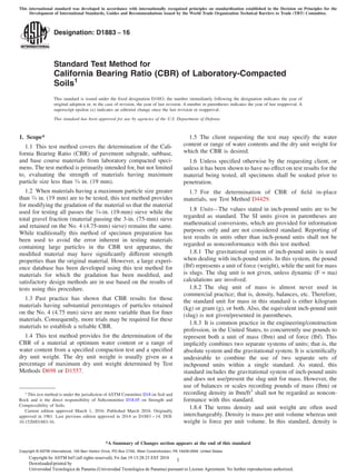
When adjusting a concave upward shaped curve, project a straight line through the straight line portion of the stress-penetration curve downward until it intersects the
penetration axis. Measure the distance (X) from the origin to the intersection. This distance (X) is then added to 0.1 and 0.2 of the penetrations and this creates a new
0.1 and 0.2 penetration. Project a straight line upward from these new penetration points until it intersects the stress-penetration curve and then select the appropriate
stress values that correspond with new 0.1 and 0.2 penetrations.
NOTE 1—See Table 2 for SI equivalents.
FIG. 5 Method for Adjusting Concave Upward Shaped Curve
FIG. 6 Dry Unit Weight Versus CBR
D1883 − 16
9Copyright by ASTM Int'l (all rights reserved); Fri Jan 19 13:28:23 EST 2018
Downloaded/printed by
Universidad Tecnologica de Panama (Universidad Tecnologica de Panama) pursuant to License Agreement. No further reproductions authorized.
10. where:
s = swell that occurred during soaking, to the nearest 0.1 %,
S = vertical swell determined from the final minus initial
swell measurement, in. (mm)
hi = height of test specimen before swell, in. (mm).
11. Report: Test Data Sheet(s)/Form(s)
11.1 The methodology used to specify how data are re-
corded on the test data sheet(s)/form(s), as given below, is
covered in 1.9. An example of data sheets is included in
Appendix X2.
11.2 Record as a minimum the following general informa-
tion (data):
11.2.1 Any special sample preparation and testing proce-
dures (for example, for self-cementing materials).
11.2.2 Sample identification (location, boring number, etc.).
11.2.3 Any pertinent testing done to describe the test sample
such as: as-received water content per Test Method D2216, soil
classifications per Test Method D2487, visual classification per
Practice D2488, Atterberg Limits per Test Method D4318,
gradation per Method D422, etc.
11.2.4 The percent material retained on the 19-mm sieve for
those cases where scalping and replacement is used.
11.2.5 Technician name/initials of personnel performing the
test.
11.2.6 Date(s) of testing.
11.3 Record as a minimum the following test specimen data:
11.3.1 Method used for preparation and compaction of
specimen: Test Methods D698 or D1557, or other, with
description.
11.3.2 Condition of sample (unsoaked or soaked).
11.3.3 Dry unit weight of sample as compacted (before
soaking) to the nearest 0.1 lbf/ft3
or 0.02 kN/m3
.
11.3.4 Water content of sample to the nearest 0.1 %:
11.3.4.1 As compacted.
11.3.4.2 Top 1-in (25.4-mm) layer after soaking.
11.3.5 Swell (percentage of initial height) to the nearest
0.1 %.
11.3.6 Stress-penetration curve.
11.3.7 Corrected CBR value of sample (unsoaked or
soaked) at 0.100 in. (2.5 mm) penetration or at 0.200 in. (5.08
mm) penetration, to the nearest 0.1 %.
11.3.8 Surcharge weight(s) used for the testing.
11.3.9 Immersion period, hours.
12. Precision and Bias
12.1 Precision—Test data on precision is not presented due
to the nature of the materials tested by this test method. It is
either not feasible or too costly at this time to have ten or more
laboratories participate in a round-robin testing program.
Notwithstanding this statement the following is offered for
guidance:
12.1.1 Single operator, based on seven repetitions, coeffi-
cient of variation (1S%) has been found to be 8.2 % (com-
pacted per Test Method D698) and 5.9 % (compacted per Test
Method D1557). Therefore, results of two properly conducted
tests by the same operator on the same material are not
expected to differ by more than 23 % (compacted per Test
Method D698) and 17 % (compacted per Test Method
D1557).4
See Appendix X1 for the data used.
12.1.2 Subcommittee D18.05 is seeking any data from the
users of this test method that might be used to make a more
thorough statement on precision.
12.2 Bias—There is no accepted reference value for this test
method, therefore, bias cannot be determined.
13. Keywords
13.1 California Bearing Ratio; CBR; pavement subgrade;
subbase; strength; pavement design
APPENDIXES
(Nonmandatory Information)
X1. COMPACTIVE EFFORT SHEET
X1.1 See Fig. X1.1 for more information.
4
These numbers represent the difference limit (d2s) as described in Practice
C670.
D1883 − 16
10Copyright by ASTM Int'l (all rights reserved); Fri Jan 19 13:28:23 EST 2018
Downloaded/printed by
Universidad Tecnologica de Panama (Universidad Tecnologica de Panama) pursuant to License Agreement. No further reproductions authorized.
11. X2. EXAMPLE DATA SHEETS
X2.1 Fig. X2.1 and Fig. X2.2 provide examples of data
sheets.
FIG. X1.1 Compactive Effort
D1883 − 16
11Copyright by ASTM Int'l (all rights reserved); Fri Jan 19 13:28:23 EST 2018
Downloaded/printed by
Universidad Tecnologica de Panama (Universidad Tecnologica de Panama) pursuant to License Agreement. No further reproductions authorized.
12. FIG. X2.1 Data Sheet Example
D1883 − 16
12Copyright by ASTM Int'l (all rights reserved); Fri Jan 19 13:28:23 EST 2018
Downloaded/printed by
Universidad Tecnologica de Panama (Universidad Tecnologica de Panama) pursuant to License Agreement. No further reproductions authorized.
13. FIG. X2.2 Data Sheet Example
D1883 − 16
13Copyright by ASTM Int'l (all rights reserved); Fri Jan 19 13:28:23 EST 2018
Downloaded/printed by
Universidad Tecnologica de Panama (Universidad Tecnologica de Panama) pursuant to License Agreement. No further reproductions authorized.
14. SUMMARY OF CHANGES
In accordance with Committee D18 policy, this section identifies the location of changes to this standard since
the last edition (2014) that may impact the use of this standard. (March 1, 2016)
(1) Reworded 1.2.
(2) Revised and added additional figures.
(3) Revised Table 2.
(4) Revised several typos and significant digits.
(5) Revised 8.2.2 and 8.2.3.
(6) Removed sentence in 10.2 concerning maximum stress.
(7) Reworded Section 12 to current wording and formatting.
(8) Added Example Data Sheets.
(9) Added Practice C670 to 2.1.
(10) Added significant digits to recording of data.
ASTM International takes no position respecting the validity of any patent rights asserted in connection with any item mentioned
in this standard. Users of this standard are expressly advised that determination of the validity of any such patent rights, and the risk
of infringement of such rights, are entirely their own responsibility.
This standard is subject to revision at any time by the responsible technical committee and must be reviewed every five years and
if not revised, either reapproved or withdrawn. Your comments are invited either for revision of this standard or for additional standards
and should be addressed to ASTM International Headquarters. Your comments will receive careful consideration at a meeting of the
responsible technical committee, which you may attend. If you feel that your comments have not received a fair hearing you should
make your views known to the ASTM Committee on Standards, at the address shown below.
This standard is copyrighted by ASTM International, 100 Barr Harbor Drive, PO Box C700, West Conshohocken, PA 19428-2959,
United States. Individual reprints (single or multiple copies) of this standard may be obtained by contacting ASTM at the above
address or at 610-832-9585 (phone), 610-832-9555 (fax), or service@astm.org (e-mail); or through the ASTM website
(www.astm.org). Permission rights to photocopy the standard may also be secured from the Copyright Clearance Center, 222
Rosewood Drive, Danvers, MA 01923, Tel: (978) 646-2600; http://www.copyright.com/
D1883 − 16
14Copyright by ASTM Int'l (all rights reserved); Fri Jan 19 13:28:23 EST 2018
Downloaded/printed by
Universidad Tecnologica de Panama (Universidad Tecnologica de Panama) pursuant to License Agreement. No further reproductions authorized.