2. 1.10 This test method is not applicable for the following
soils:
1.10.1 Soils containing fibrous peat that will change in
particle size during the drying, washing, or sieving procedure.
1.10.2 Soils containing extraneous matter, such as organic
solvents, oil, asphalt, wood fragments, or similar items. Such
extraneous matter can affect the washing and sieving proce-
dures.
1.10.3 Materials that contain cementitious components,
such as cement, fly ash, lime, or other stabilization admixtures.
1.11 This test method may not produce consistent test
results within and between laboratories for the following soils
and the precision statement does not apply to them.
1.11.1 Friable soils in which the sieving processes change
the gradation of the soil. Typical examples of these soils are
some residual soils, most weathered shales and some weakly
cemented soils such as hardpan, caliche or coquina.
1.11.2 Soils that will not readily disperse such as glauconitic
clays or some dried plastic clays.
1.11.3 To test these soils, this test method must be adapted,
or altered, and these alterations documented. Depending on the
design considerations, a specialized gradation-testing program
could be performed. The alterations could require the washing
and sieving procedures to be standardized such that each
specimen would be processed in a similar manner.
1.12 Some materials that are not soils, but are made up of
particles may be tested using this method. However, the
applicable sections above should be used in applying this
standard.
1.13 All observed and calculated values shall conform to the
guidelines for significant digits and rounding established in
Practice D6026, unless superseded by this test method.
1.13.1 The procedures used to specify how data are
collected/recorded and calculated in this standard are regarded
as the industry standard. In addition, they are representative of
the significant digits that generally should be retained. The
procedures used do not consider material variation, purpose for
obtaining the data, special purpose studies, or any consider-
ations for the user’s objectives; and it is common practice to
increase or reduce significant digits of reported data to be
commensurate with these considerations. It is beyond the scope
of these test methods to consider significant digits used in
analysis methods for engineering design.
1.14 Units—The dimensional values stated in either SI units
or inch-pound units are to be regarded as standard, such as
200-mm or 8-in. diameter sieve. Except, the sieve designations
are typically identified using the “alternative” system in
accordance with Practice E11, such as 3 in. and No. 200,
instead of the “standard” system of 75 mm and 75 µm,
respectively. Only the SI units are used for mass
determinations, calculations, and reported results. However,
the use of balances or scales recording pounds of mass (lbm)
shall not be regarded as nonconformance with this standard.
1.15 A summary of the symbols used in this test method is
given in Annex A1.
1.16 This standard does not purport to address all of the
safety concerns, if any, associated with its use. It is the
responsibility of the user of this standard to establish appro-
priate safety and health practices and determine the applica-
bility of regulatory limitations prior to use.
1.17 Table of Contents—All tables and figures appear at the
end of this standard.
Section
Scope 1
Method A 1.6.1
Method B 1.6.2
Sample Processing 1.8
Units 1.14
Referenced Documents 2
ASTM Standards 2.1
Terminology 3
General 3.1
Definitions 3.2
Definitions of Terms Specific to This
Standard
3.3
Summary of Test Method 4
Significance and Use 5
Apparatus 6
Sieves 6.1
Standard Sieve Set 6.1.1
Washing Sieve, No. 200 (75-µm) 6.1.2
Designated Separating Sieve 6.1.3
Washing Sink with Spray Nozzle 6.2
Mechanical Sieve Shaker 6.3
Balances 6.4
Drying Oven 6.5
Sieving Containers 6.6
Specimen Containers 6.6.1
Collection/Transfer Device 6.6.2
Cumulative Mass Container 6.6.3
Sieve Brushes 6.7
Miscellaneous Items 6.8
Splitter or Riffle Box (optional) 6.9
Quartering Accessories (optional) 6.10
Mortar and Rubber-Covered Pestle
(optional)
6.11
Low Temperature Drying Oven
(optional)
6.12
Ultrasonic Water Bath (optional) 6.13
Dispersion Shaker (optional) 6.14
Reagents 7
Sodium Hexametaphosphate 7.1
Dry Addition 7.1.1.1
Solution 7.1.1.2
Preparation of Apparatus 8
Verification of Sieves 8.1
Verification Interval 8.1.1
Verification of Mechanical Sieve Shaker
and
Standard Shaking Period
8.2
Large Mechanical Sieve Shaker 8.2.1
Verification Interval 8.2.2
Hand Sieve Shaking Procedure 8.2.3
Sampling 9
General 9.1
Sample Sources 9.2
Bulk Samples 9.2.1
Jar and Small Bag Samples 9.2.2
Intact Tube Samples 9.2.3
Samples from Prior Testing 9.2.4
Specimen 10
General 10.1
Minimum Mass Requirement 10.2
Selection of Sieving Procedure 10.3
Single Sieve-Set Sieving 10.3.1
Composite Sieving 10.3.2
Specimen Procurement 10.4
Moist Procedure 10.4.1
Air-Dried Procedure 10.4.2
Oven-Dried Procedure 10.4.3
Discussion on Segregating Soils 10.4.4
Specimen Procurement and Processing
Requirements
10.5
D6913/D6913M − 17
2Copyright by ASTM Int'l (all rights reserved); Wed Oct 17 12:46:01 EDT 2018
Downloaded/printed by
Universidad Catolica del Norte (Universidad Catolica del Norte) pursuant to License Agreement. No further reproductions authorized.
3. Moist Procedure, Single Sieve-Set
Sieving
10.5.1
Moist Procedure, Composite Sieving 10.5.2
Coarse Portion Acceptable Loss
(CPL)
10.5.2.3
Air-Dried Procedure, General 10.5.3
Air-Dried Procedure, Single Sieve-
Set Sieving
10.5.4
Air-Dried Procedure, Composite
Sieving
10.5.5
Oven-Dried Procedure, General 10.5.6
Oven-Dried Procedure, Single Sieve-
Set Sieving
10.5.7
Oven-Dried Procedure, Composite
Sieving
10.5.8
Procedure (Sieving) 11
General 11.1
Mass Measurements 11.2
Sieve Overloading 11.3
Single Sieve-Set Sieving 11.4
Specimen Mass 11.4.1
Specimen Dispersion 11.4.2
Soaking without a Dispersant 11.4.2.1
Soaking with a Dispersant 11.4.2.2
Using an Ultrasonic Water Bath 11.4.2.3
Washing Specimen 11.4.3
General Precautions 11.4.3.1
Transfer Specimen 11.4.3.2
Washing 11.4.3.3
Transfer Washed Specimen 11.4.3.4
Dry Sieving 11.4.4
Sieve Set 11.4.4.1
Mechanical Shaking 11.4.4.2
Cumulative Material/Mass Retained 11.4.5
First Sieve 11.4.5.1
Remaining Sieves 11.4.5.2
Composite Sieving, Single Separation 11.5
Coarser Portion 11.5.1
Dispersing and Washing 11.5.1.1
Dry Sieving Coarser Portion 11.5.1.3
Subspecimen from Finer Portion 11.5.2
Dispersing and Washing
Subspecimen
11.5.2.1
Dry Sieving Subspecimen 11.5.2.2
Composite Sieving, Double Separation 11.6
Separating 1st
Subspecimen 11.6.1
Dispersing and Washing 2nd
Coarser
Portion
11.6.2
Dry Sieving 2nd
Coarser Portion 11.6.3
2nd
Subspecimen 11.6.4
Dispersing and Washing 2nd
Subspecimen
11.6.4.1
Dry Sieving 2nd
Subspecimen 11.6.4.2
Calculations 12
General 12.1
Sieve Overloading 12.2
Single Sieve-Set Sieving, Percent
Passing
12.3
Composite Sieving, Mass of Specimen 12.4
Composite Sieving, Single Separation 12.5
Composite Sieving, Coarser Portion
(CP)
12.5.1
CP, Percent Passing 12.5.1.1
CP, Composite Sieving Correction
Factor (CSCF)
12.5.1.2
CP, Acceptable Loss During
Washing
and Sieving
12.5.1.3
Composite Sieving, Subspecimen
(finer
portion)
12.5.2
Percent Passing, Specimen
(combined
coarser and finer portions)
12.5.2.1
Subspecimen, Acceptable
Fractional
Percent Retained
12.5.2.2
Percent Passing, Acceptance
Criterion
12.5.2.3
Finer Portion, Percent Passing
(optional)
12.5.3
Composite Sieving, Double Separation 12.6
1st
Coarser Portion 12.6.1
1st
Subspecimen 12.6.2
Percent Passing, 2nd
Coarser
Portion
12.6.2.1
2nd
Coarser Portion, Composite
Sieving
Correction Factor (2nd
CSCF)
12.6.2.2
2nd
Coarser Portion, Acceptable
Loss on
Sieving and Washing
12.6.2.3
2nd
Coarser Portion, Acceptable
Fractional
Percent Retained
12.6.2.4
Percent Passing, Acceptance
Criterion
12.6.2.5
2nd
Subspecimen 12.6.3
Percent Passing, 2nd
Subspecimen 12.6.3.1
2nd
Subspecimen, Acceptable
Fractional
Percent Retained
12.6.3.2
Percent Passing, Acceptance
Criterion
12.6.3.3
1st
Finer Portion, Percent Passing
(optional)
12.6.4
2nd
Finer Portion, Composite
Sieving
Correction Factor (optional)
12.6.4.1
2nd
Finer Portion, Percent Passing
for
2nd
Subspecimen (optional)
12.6.4.2
Report: Test Data Sheet(s)/Form(s) 13
Precision and Bias 14
Precision 14.1
Precision Data Analysis 14.1.1
Calculation of Precision 14.1.2
Acceptance Criterion 14.1.2.4
Triplicate Test Precision Data (TTPD) 14.1.3
TTPD-Method A Repeatability 14.1.3.1
TTPD-Method A Reproducibility 14.1.3.2
TTPD-Method B Repeatability 14.1.3.3
TTPD-Method B Reproducibility 14.1.3.4
Single Test Precision Data (STPD) 14.1.4
STPD-Method A Reproducibility 14.1.4.1
STPD-Method B Reproducibility 14.1.4.2
Soils Type 14.1.5
Discussion on Precision 14.1.6
Bias 14.2
Keywords 15
ANNEXES
Symbols Annex A1
Sample to Specimen Splitting/Reduction
Methods
Annex A2
General A2.1
Mechanical Splitting A2.1.1
Quartering A2.1.2
Miniature Stockpile Sampling A2.1.3
Sample Processing Recommendation
Based
on Soil Type
A2.2
Clean Gravel (GW, GP) and Clean
Sand
(SW, SP)
A2.2.1
Gravel with Fines (GM, GC, GC-GM,
GW-GM, GP-GM, GP-GC)
A2.2.2
Sand with Silt Fines (SW-SM, SP-
SM,
SM)
A2.2.3
Sand with Clay and Silt Fines or Clay
Fines (SW-SC, SP-SC, SC, SC-
SM)
A2.2.4
D6913/D6913M − 17
3Copyright by ASTM Int'l (all rights reserved); Wed Oct 17 12:46:01 EDT 2018
Downloaded/printed by
Universidad Catolica del Norte (Universidad Catolica del Norte) pursuant to License Agreement. No further reproductions authorized.
4. Silts with Sand or Gravel, or Both
(ML,
MH)
A2.2.5
Organic Soils with Sand or Gravel, or
Both (OL, OH)
A2.2.6
APPENDIXES
Example Test Data Sheets/Forms Appendix X1
General X1.1
Precision: Example Calculations Appendix X2
General X2.1
TABLES and FIGURES
1.18 This international standard was developed in accor-
dance with internationally recognized principles on standard-
ization established in the Decision on Principles for the
Development of International Standards, Guides and Recom-
mendations issued by the World Trade Organization Technical
Barriers to Trade (TBT) Committee.
2. Referenced Documents
2.1 ASTM Standards:2
C136 Test Method for Sieve Analysis of Fine and Coarse
Aggregates
C702 Practice for Reducing Samples of Aggregate to Testing
Size
D653 Terminology Relating to Soil, Rock, and Contained
Fluids
D698 Test Methods for Laboratory Compaction Character-
istics of Soil Using Standard Effort (12,400 ft-lbf/ft3
(600
kN-m/m3
))
D1140 Test Methods for Determining the Amount of Mate-
rial Finer than 75-µm (No. 200) Sieve in Soils by Washing
D1557 Test Methods for Laboratory Compaction Character-
istics of Soil Using Modified Effort (56,000 ft-lbf/ft3
(2,700 kN-m/m3
))
D2216 Test Methods for Laboratory Determination of Water
(Moisture) Content of Soil and Rock by Mass
D2487 Practice for Classification of Soils for Engineering
Purposes (Unified Soil Classification System)
D2488 Practice for Description and Identification of Soils
(Visual-Manual Procedures)
D3740 Practice for Minimum Requirements for Agencies
Engaged in Testing and/or Inspection of Soil and Rock as
Used in Engineering Design and Construction
D4220/D4220M Practices for Preserving and Transporting
Soil Samples
D4318 Test Methods for Liquid Limit, Plastic Limit, and
Plasticity Index of Soils
D4753 Guide for Evaluating, Selecting, and Specifying Bal-
ances and Standard Masses for Use in Soil, Rock, and
Construction Materials Testing
D5519 Test Methods for Particle Size Analysis of Natural
and Man-Made Riprap Materials
D6026 Practice for Using Significant Digits in Geotechnical
Data
D7928 Test Method for Particle-Size Distribution (Grada-
tion) of Fine-Grained Soils Using the Sedimentation
(Hydrometer) Analysis
E11 Specification for Woven Wire Test Sieve Cloth and Test
Sieves
E177 Practice for Use of the Terms Precision and Bias in
ASTM Test Methods
E691 Practice for Conducting an Interlaboratory Study to
Determine the Precision of a Test Method
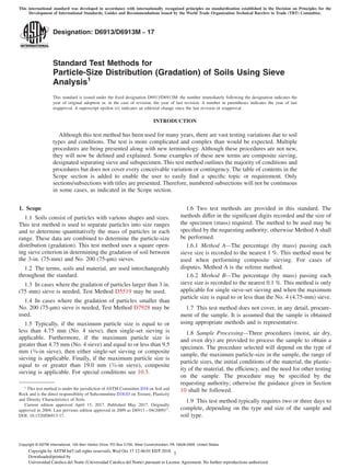
3. Terminology
3.1 General:
3.1.1 An overview of terms used in the sieving processes is
presented in Fig. 1(a) using a tabular format and in Fig. 1(b)
using a flowchart format. In addition, Fig. 1(a) includes
symbols used in the sieving processes.
3.1.2 There are two types of definitions in the following
sections. There are definitions that are general (see 3.2) and
others that are specific to this standard (see 3.3). To locate a
definition, it may be necessary to review both sections. The
definitions are in alphabetical order.
3.2 Definitions:
3.2.1 For definitions of general terms used in this test
method, refer to Terminology D653.
3.2.2 composite sieving, v—in sieving, the process of sepa-
rating a large specimen on a designated separating sieve to
obtain coarser and finer particle-size portions. The coarser
portion is sieved using the coarser sieve set. The finer portion
is subsampled to obtain a subspecimen of manageable size
(mass) and this subspecimen is sieved using the finer sieve set.
The results of both sieve sets (coarser and finer) are combined
mathematically to determine the gradation of the large speci-
men.
3.2.2.1 Discussion—In some cases the subspecimen may
require another separation; that is, using a 2nd
designated
separating sieve and resulting in a 2nd
coarser portion and 2nd
subspecimen obtained from the 2nd
finer portion.
3.2.3 cumulative material retained (cumulative retained
material or cumulative mass retained), n—in sieving, the mass
of material retained on an individual sieve plus the masses of
material retained on all the coarser sieves in a given stack/set
of sieves.
3.2.4 cumulative percent retained, n—in sieving, the ratio of
cumulative material retained on a given sieve to the mass of the
specimen, expressed in percent.
3.2.5 designated separating sieve, n—in composite sieving,
the sieve selected to separate the specimen into coarser and
finer portions for composite sieving.
3.2.5.1 Discussion—The designated separating sieve size is
a standard sieve size typically ranging from the 3⁄4-in. (19.0-
mm) sieve to the No. 10 (2.00-mm) sieve. There can be two
designated separating sieves used in composite sieving, that is
the 1st
subspecimen can be separated on a 2nd
designated
separating sieve to obtain a 2nd
coarser portion and a 2nd
sub-
specimen obtained from the 2nd
finer portion.
3.2.6 fractional cumulative material retained, n—in com-
posite sieving, when sieving a subspecimen, the mass of
material retained on an individual sieve plus the masses of
material retained on all the coarser sieves in a given sieve set.
2
For referenced ASTM standards, visit the ASTM website, www.astm.org, or
contact ASTM Customer Service at service@astm.org. For Annual Book of ASTM
Standards volume information, refer to the standard’s Document Summary page on
the ASTM website.
D6913/D6913M − 17
4Copyright by ASTM Int'l (all rights reserved); Wed Oct 17 12:46:01 EDT 2018
Downloaded/printed by
Universidad Catolica del Norte (Universidad Catolica del Norte) pursuant to License Agreement. No further reproductions authorized.
5. FIG. 1 (a) Typical Terminology and Symbols Used in Sieving Processes
D6913/D6913M − 17
5Copyright by ASTM Int'l (all rights reserved); Wed Oct 17 12:46:01 EDT 2018
Downloaded/printed by
Universidad Catolica del Norte (Universidad Catolica del Norte) pursuant to License Agreement. No further reproductions authorized.
6. 3.2.7 fractional cumulative percent retained, n—in compos-
ite sieving, the ratio of fractional cumulative material retained
on a given sieve to the mass of the subspecimen, expressed in
percent.
3.2.8 fractional material retained, n—in composite sieving,
when sieving a subspecimen, the mass of material retained on
an individual sieve.
3.2.9 fractional percent passing, n—in composite sieving,
the portion of material by mass in the subspecimen(s) passing
a given sieve expressed in percent.
3.2.9.1 Discussion—When two subspecimens are used,
there will be a 1st
and 2nd
fractional percent passing.
3.2.10 fractional percent retained, n—in composite sieving,
the ratio of fractional material retained on a given sieve to the
mass of the subspecimen, expressed in percent.
3.2.11 gradation, n—in soil, the proportion by mass of
various particle sizes.
3.2.11.1 Discussion—This proportion is usually presented
in tabular format (sieve size and percent passing) or graphical
format (percent passing versus logarithm of the sieve size in
mm). The graphical format is referred to as particle-size
distribution or gradation curve.
3.2.12 maximum particle size, n—in sieving, the smallest
sieve size from the standard sieve set on which less than one
percent of the sample would be retained.
3.2.12.1 Discussion—For practical purposes, estimate the
maximum particle size as equal to the smallest sieve size from
the standard sieve set in which it appears that all the material
being tested would pass through that sieve. The maximum
particle size is needed to determine the required mass of the
specimen and subspecimen.
3.2.13 maximum sieve size, n—in sieving, the smallest sieve
size that is larger than any particle in the specimen or
subspecimen.
3.2.14 minimum sieve size, n—in sieving, the smallest sieve
size in a sieve set used in sieving the specimen or subspecimen.
3.2.14.1 Discussion—This size is either the size of the
designated separating sieve (1st
or 2nd
) or the No. 200 (75-µm)
sieve.
3.2.15 percent passing, n—in sieving, the portion of mate-
rial by mass in the specimen passing a given sieve expressed in
percent.
3.2.15.1 Discussion—This value is equal to the cumulative
material retained in a given sieve set divided by the mass of the
FIG. 1 (b) Terminology Flowchart for Sieving Processes (continued)
D6913/D6913M − 17
6Copyright by ASTM Int'l (all rights reserved); Wed Oct 17 12:46:01 EDT 2018
Downloaded/printed by
Universidad Catolica del Norte (Universidad Catolica del Norte) pursuant to License Agreement. No further reproductions authorized.
7. specimen, subtracting that ratio from one, and then multiplying
by 100. For composite sieving, it would be the fractional
percent passing multiplied by the composite sieving correction
factor (CSCF).
3.2.16 particle size distribution, n—see gradation.
3.2.17 percent retained, n—in sieving, the ratio of the
material retained on a given sieve to the mass of the specimen,
expressed in percent.
3.2.18 saturated surface-dry condition, n—in coarse-
grained soils, a state in which the soil particles are basically
saturated with water, but there are not visible films of water.
3.2.19 sieve set, n—in sieving, a set of standard sized sieves.
For single sieve-set sieving, the sieve set will range from the
maximum sieve size to the No. 200 (75-µm) sieve. For
composite sieving, there will be a coarser sieve set and a finer
sieve set. Together, these sets will range from the maximum
sieve size to the No. 200 (75-µm) sieve. The designated
separating sieve will be used as the minimum size in the
coarser set and the maximum size in the finer set.
3.2.20 sieve size, n—in sieving, the size of the opening in the
wire cloth of a given sieve in mm or µm.
3.2.21 single sieve-set sieving, v—in sieving, the process in
which only one set of sieves is needed to determine the
gradation of the specimen from the maximum particle size to
the No. 200 (75-µm) sieve.
3.2.21.1 Discussion—Typically, this applies to specimens
having a maximum particle size of 9.5 mm (3⁄8 in.) or less when
using Method A or a maximum particle size of 4.75 mm (No.
4 sieve) or less when using Method B and the distribution of
particles less than the No. 200 (75-µm) sieve is not needed.
3.2.22 splitting, v—in sampling or subsampling, the process
of stockpile sampling, quartering material, or passing material
through a splitter or riffle box to obtain a representative portion
of that material for testing; that is, a specimen or subspecimen.
3.2.22.1 Discussion—A description of stockpile sampling,
and quartering and splitting material is given in Annex A2,
A2.1.1 through A2.1.3.
3.2.23 standard shaking period, n—in sieving, a time period
ranging from 10 to 20 minutes that a mechanical sieve shaker
operates during the sieving process and which has been verified
to satisfy the requirements for sieving thoroughness.
3.2.24 standard sieve set, n—in sieving soils, the group of
fourteen specific sieve sizes required to determine the grada-
tion of soils between and including the 3-in. (75-mm) and No.
200 (75-µm) sieves, as listed in Table 1.
3.2.24.1 Discussion—Most of these sieve sizes are different
than those used in aggregate testing for concrete (Test Method
C136), especially for sieves finer than the No. 4 (4.75 mm).
3.2.25 subspecimen, n—in composite sieving, a representa-
tive portion of the material passing the designated separating
sieve; that is, the finer portion.
3.2.25.1 Discussion—When composite sieving requires
multiple designated separating sieves, there will be more than
one subspecimen. The 1st
subspecimen (that is, the subspeci-
men from the finer portion) would be separated into a 2nd
coarser portion and a 2nd
finer portion that would be sub-
sampled to obtain the 2nd
subspecimen.
3.3 Definitions of Terms Specific to This Standard:
3.3.1 coarser portion, n—in composite sieving, the portion
of the specimen retained on the designated separating sieve.
3.3.1.1 Discussion—When two designated separating sieves
are used, there will be a 1st
and 2nd
coarser portion.
3.3.2 coarser sieve set, n—in composite sieving, the sieve
set that ranges from the maximum sieve size to the designated
separating sieve size.
3.3.2.1 Discussion—When two designated separating sieves
are used, the 1st
coarser sieve set ranges from the maximum
sieve size to the 1st
designated separating sieve size. The 2nd
coarser sieve set would range from the 1st
designated separat-
ing sieve size to the 2nd
designated separating sieve size.
3.3.3 composite sieving correction factor (CSCF), n—in
composite sieving, a factor used to convert the fractional
percent passing determined from sieving the subspecimen to
the percent passing for the specimen. The CSCF is equal to the
percent passing the designated separating sieve size in the
coarser portion sieve set (that is, the last sieve in the coarser
portion set). This value shall be calculated to one more digit
than required (0.1 %) to reduce rounding errors.
3.3.3.1 Discussion—When two designated separating sieves
are used, there will be a 1st
and 2nd
CSCF.
3.3.4 finer portion, n—in composite sieving, the portion of
the specimen passing the designated separating sieve.
3.3.4.1 Discussion—When two designated separating sieves
are used, the 1st
subspecimen obtained from the 1st
finer
portion will be separated into a 2nd
coarser portion and 2nd
finer
portion, from which the 2nd
subspecimen is obtained.
TABLE 1 Standard Sieve SetA
Sieve Designation in Accordance with E11
Alternative Standard Alternative Standard
Lid No. 10 2.00 mm
3 in. 75 mm No. 20 850 µm
2 in. 50 mm No. 40 425 µm
1-1⁄2 in. 37.5 mm No. 60 250 µm
1 in. 25.0 mm No. 100 150 µm
3⁄4 in. 19.0 mm No. 140 106 µm
3⁄8 in. 9.5 mm No. 200 75 µm
No. 4 4.75 mm Pan
A
A lid is typically not used or needed when using rectangular coarser sieves having
dimensions greater than 200 mm or 8 in.
D6913/D6913M − 17
7Copyright by ASTM Int'l (all rights reserved); Wed Oct 17 12:46:01 EDT 2018
Downloaded/printed by
Universidad Catolica del Norte (Universidad Catolica del Norte) pursuant to License Agreement. No further reproductions authorized.
8. 3.3.5 finer sieve set, n—in composite sieving, the sieve set
that ranges from the last designated separating sieve size to the
No. 200 (75-µm) sieve.
3.3.5.1 Discussion—When composite sieving requires a 2nd
subspecimen, the finer sieve sets ranges from the 2nd
separating
sieve size to the No. 200 (75-µm) sieve.
3.3.6 insignificant sieve, n—in precision of test results, any
sieve which has 1 % or less cumulative material retained
during the sieve analysis.
3.3.7 separating, v—in composite sieving, the process of
dividing a specimen or subspecimen into two portions, the
coarser (retained) and finer (passing) portions, using a desig-
nated separating sieve.
3.3.7.1 Discussion—When composite sieving requires two
designated sieves, there will be a 1st
and 2nd
coarser portion,
finer portion and subspecimen.
3.3.8 significant sieve, n—in precision of test results, any
sieve which has more than 1 % of cumulative material retained
during the sieve analysis.
4. Summary of Test Method
4.1 This test method is used to determine the particle-size
distribution (gradation) of a soil sample. A representative
specimen must be obtained from the sample by one of three
procedures (moist, air-dried or oven-dried). For specimens
containing relatively small particles, the specimen is sieved in
its entirety, using single sieve-set sieving. However, the speci-
men may contain a wide range of particle sizes and may require
separating the soil into two, or three size ranges for more
efficient sieving, using one or two designated separating
sieve(s). This process is termed composite sieving. For a single
separation (two portions), the coarser portion is sieved in its
entirety, while the finer portion is split into a smaller subspe-
cimen for sieving. These results are mathematically combined.
For specimens containing very large particles, the specimen
may require two separations; that is, three portions (1st
and 2nd
coarser portions and 2nd
finer portion), see Fig. 1(a) and Fig.
1(b). Prior to sieving, as applicable, the material will be
washed to remove fine particles and oven dried. The material to
be sieved will be placed on the coarsest sieve size of each sieve
set and mechanically shaken. The mass of particles retained on
each sieve will be determined. The results will produce a
tabulation of sieve sizes versus percent passing that can be
graphically presented as a gradation curve (a plot of the percent
passing versus the log of the particle size in mm.).
4.2 Flowcharts outlining the requirements of the various
sieving processes covered above are presented below in four
figures, Fig. 2 through Fig. 4(b).
5. Significance and Use
5.1 The gradation of the soil is used for classification in
accordance with Practice D2487.
5.2 The gradation (particle-size distribution) curve is used
to calculate the coefficient of uniformity and the coefficient of
curvature.
5.3 Selection and acceptance of fill materials are often based
on gradation. For example, highway embankments, backfills,
and earthen dams may have gradation requirements.
5.4 The gradation of the soil often controls the design and
quality control of drainage filters, and groundwater drainage.
5.5 Selection of options for dynamic compaction and grout-
ing is related to gradation of the soil.
5.6 The gradation of a soil is an indicator of engineering
properties. Hydraulic conductivity, compressibility, and shear
strength are related to the gradation of the soil. However,
engineering behavior is dependent upon many factors (such as
effective stress, stress history, mineral type, structure,
plasticity, and geologic origins) and cannot be based solely
upon gradation.
NOTE 1—The quality of the result produced by these test methods is
dependent on the competence of the personnel performing it, and the
suitability of the equipment and facilities used. Agencies that meet the
criteria of Practice D3740 are generally considered capable of competent
and objective testing/sampling/inspection/etc. Users of these test methods
are cautioned that compliance with Practice D3740 does not in itself
assure reliable results. Reliable results depend on many factors; Practice
D3740 provides a means of evaluating some of those factors.
6. Apparatus
6.1 Sieves—Each sieve shall conform to the requirements of
Specification E11. Generally, these sieve frames are circular
and 200 mm or 8 in. in diameter, and either full (50 mm or 2
in.) or half height (25 mm or 1 in.). The sieve height generally
depends upon the number of sieves typically required in the
sieve set, the particle sizes being sieved, and the size and type
of the sieve shaker. Particles having dimensions exceeding or
relatively close to the sieve heights cannot be sieved in the
sieve stack, but individually. Therefore, in a stack of sieves, the
ratio of sieve height or spacing between rectangular sieves to
sieve cloth opening shall exceed 2. Larger frames that conform
to Specification E11 are acceptable but require special consid-
erations for reinforcement.
6.1.1 Standard Sieve Set—This set consists of all the sieve
sizes listed in Table 1. Additional sieves sizes may be added if
requested or needed to reduce sieve overloading. In addition,
some larger sieve sizes may be omitted during the sieve
analysis depending on the maximum particle size; however, at
least one sieve in the sieving process shall have 100 percent
passing.
6.1.2 Washing Sieve, No. 200 (75-µm)—A No. 200 (75-µm)
sieve with a minimum height above the screen of 50 mm or 2
in. to prevent loss of retained material while washing. Stainless
steel sieve cloth is preferred because it is more durable, and
less prone to damage or wear. The sieve may be reinforced with
a larger mesh underneath the 75-µm cloth. The reinforcement
wire cloth (backing) should not have a mesh coarser than the
No. 20 (850-µm) wire cloth. The reinforcement wire cloth
should be bonded to the sieve frame along with the No. 200
(75-µm) wire cloth, not bonded to the sieve frame below where
the No. 200 (75-µm) wire cloth was attached. In addition, it is
good practice to use a flattened backing cloth (rolled or
calendered backing cloth), so it is less abrasive to the No. 200
(75-µm) wire cloth.
D6913/D6913M − 17
8Copyright by ASTM Int'l (all rights reserved); Wed Oct 17 12:46:01 EDT 2018
Downloaded/printed by
Universidad Catolica del Norte (Universidad Catolica del Norte) pursuant to License Agreement. No further reproductions authorized.
9. 6.1.3 Designated Separating Sieve—A sieve used to sepa-
rate the specimen into two portions (coarser and finer portion)
in composite sieving. The designated separating sieve shall
conform to Specification E11. It may be necessary to have
various sizes of sieves to use as designated separating sieves.
Normally, these are not the same sieves that are used in the
stack of sieves (sieve set) placed in the sieve shaker. Typically,
the 1st
designated separating sieve is rectangular and quite
large, while the 2nd
designated separating sieve is either
200-mm or 8-in. in diameter.
6.2 Washing Sink with Spray Nozzle—A sink having a spray
nozzle attached to a flexible line to facilitate the washing and
material transferring processes without spillage. In addition,
the spray nozzle shall be such that the rate of water flow can be
easily controlled. The temperature of the water shall be
FIG. 2 Decision Flowchart for Sieving Processes
D6913/D6913M − 17
9Copyright by ASTM Int'l (all rights reserved); Wed Oct 17 12:46:01 EDT 2018
Downloaded/printed by
Universidad Catolica del Norte (Universidad Catolica del Norte) pursuant to License Agreement. No further reproductions authorized.
10. relatively close to room temperature to prevent changing the
dimensions of the sieve cloth and health and safety concerns.
6.3 Mechanical Sieve Shaker—A device that holds a stack
of sieves while imparting sufficient motion to the sieves to
meet the sieving thoroughness requirements covered in 8.2.
The “Standard Shaking Period” must be from 10 to 20 minutes.
The shaker shall have a timing device or a timing device shall
be used in conjunction with the shaker.
NOTE 2—Shakers imparting a motion that causes the particles on the
sieves to bounce and turn so that all particles have ample opportunity in
various orientations to the sieve openings will typically meet this sieving
thoroughness requirement. A sieve shaker that has a smooth horizontal
and/or vertical gyratory/orbital motion will typically not meet this sieving
thoroughness requirement, since the particles will not be bouncing and
turning.
6.4 Balances—For single sieve-set sieving, one balance will
be used. For composite sieving, more than one balance may be
necessary. Balances must conform to the requirements of
Specification D4753; that is, having a readability (with no
estimation) to determine the mass of the specimen or subspe-
cimen to a minimum of three significant digits for Method A or
a minimum four significant digits for Method B. The mass of
the specimen can be determined in parts (multiple mass
determinations). The balance used to determine the cumulative
material retained or the fractional cumulative material retained
on any given sieve has to have a readability equal to or better
than that used to determine the mass of the specimen/
subspecimen.
NOTE 3—Preferably the balance should have a taring capability so that
the mass of material can be directly determined without subtracting the
mass of the container. This feature is immensely useful during the sieving
process to determine the mass of the cumulative material retained or when
making multiple mass determinations to determine specimen’s mass.
6.5 Drying Oven—Thermostatically controlled oven, ca-
pable of maintaining a uniform temperature of 110 6 5°C
throughout the drying chamber. These requirements typically
require the use of a forced-draft oven.
6.6 Sieving Containers—The containers used to: (a) contain
the sieving specimen or material which will be sieved, such as
coarser portion; (b) remove the retained material from the
sieve(s); (c) collect and transfer that material; and, (d) contain
the cumulative material retained.
6.6.1 Specimen Containers—Smooth walled containers,
without tight corners to trap material, made of material
resistant to corrosion and change in mass upon repeated
heating, cooling, specimen soaking, and cleaning. The contain-
ers should be large enough to enable soaking of the specimen.
The container should facilitate the transfer of the specimen
from the container to the washing sieve (No. 200 (75 µm) or
designated separating sieve) and back by a rinsing/washing
operation, and allow for decanting the clear wash water from
the container.
6.6.2 Collection/Transfer Container—This container is used
to collect the material retained on a given sieve and to transfer
it to the container holding the cumulative retained material
during the sieving process. The container must be larger in
diameter than the sieve. A smoothsurface 230-mm (9-in.) pie
pan may be used along with a 25-mm (1-in.) paintbrush to
assist in transferring all the material. The color of this container
shall enhance the observation that all material has been
transferred.
6.6.3 Cumulative Mass Container—This container shall be
large enough to receive the retained material contained in the
collection/transfer device without any loss. The mass should be
FIG. 3 Flowchart for Single Sieve-Set Sieving
D6913/D6913M − 17
10Copyright by ASTM Int'l (all rights reserved); Wed Oct 17 12:46:01 EDT 2018
Downloaded/printed by
Universidad Catolica del Norte (Universidad Catolica del Norte) pursuant to License Agreement. No further reproductions authorized.
11. FIG. 4 (a) Flowchart for Composite Sieving—Single Separation
D6913/D6913M − 17
11Copyright by ASTM Int'l (all rights reserved); Wed Oct 17 12:46:01 EDT 2018
Downloaded/printed by
Universidad Catolica del Norte (Universidad Catolica del Norte) pursuant to License Agreement. No further reproductions authorized.
12. FIG. 4 (b) Flowchart for Composite Sieving—Double Separation (continued)
D6913/D6913M − 17
12Copyright by ASTM Int'l (all rights reserved); Wed Oct 17 12:46:01 EDT 2018
Downloaded/printed by
Universidad Catolica del Norte (Universidad Catolica del Norte) pursuant to License Agreement. No further reproductions authorized.
13. less than the taring capacity of the balance so that the
cumulative mass retained can be determined directly (see Note
3). In most cases, the specimen/subspecimen container can be
used. This test method assumes that the mass of the cumulative
retained material is determined directly. This approach is easier
than determining the mass of retained material on each sieve.
6.7 Sieve Brushes—Brushes to assist in the removal of the
material retained on the smaller (≤200-mm or 8-in.) diameter
and finer sieve sizes (≤3⁄4-in. (19.0-mm)). The brushes shall
have the following characteristics:
6.7.1 The bristles shall be firmly attached to the brush
handle so that the bristles do not become part of the retained
material.
6.7.2 The bristles shall be firm and small enough to readily
remove the particles entangled in the sieve openings, but made
of a material that will not damage the wire cloth or wear
rapidly. Wire bristles, even brass, shall not be used on wire
cloth size finer than No. 20 (850–µm).
6.7.3 The bristles shall be capable of contacting the bound-
ary between the wire cloth and sieve’s frame.
6.7.4 The brush’s handle shall be such that one’s hand can
easily control the brushing motion and pressure. An example
being, the handle is above the bristles (like a paintbrush) or
inclined (30- to 45-degree angle) to the bristle’s head (like a
vegetable brush or bent toothbrush).
6.7.5 The bristles have to be small in diameter and soft
when brushing wire cloth size equal to or less than the No. 100
(150-µm) mesh. Small diameter, soft bristles will remove the
particles without any re-alignment of the wire cloth.
6.7.6 Brushes meeting these requirements are relatively
small round or rectangular stiff paintbrushes with shortened
bristles, soft to hard toothbrushes with bent handles, and
vegetable brushes with shortened bristles.
6.8 Miscellaneous Items—Miscellaneous items such as
wash bottle, spatula, and stirring rod may be useful.
6.9 Splitter or Riffle Box (optional, but may be needed
during composite sieving)—A device to obtain a representative
smaller portion (specimen) from a larger portion (sample). This
device has an even number of equal width chutes, but not less
than eight, which discharge alternately to each side of the
splitter. For dry material having particles coarser than the 3⁄8-in.
(9.5-mm) sieve size, the minimum width of the chutes shall be
approximately 1-1⁄2 times the largest particle in material being
split, but not less than 12.5 mm or 1⁄2 in. For dry material finer
than or equal to the 3⁄8-in. (9.5-mm) sieve size, the minimum
chute width shall be approximately 1-1⁄2 times the largest
particle in the material, but not less than approximately 3 mm
or 1⁄8 in. The splitter shall be equipped with two or more
receptacles to hold the two halves of the material following
splitting. It shall also be equipped with a hopper/feed chute
(preferably lever activated or having a cut-off gate) and a
straight-edged pan or dustpan that has a width equal to or
slightly less than the over-all width of the assembly of chutes,
by which the dry material may be fed at a controlled rate to the
chutes. The splitter and accessory equipment shall be so
designed that the material will flow smoothly without restric-
tion or loss of material.
NOTE 4—Some splitters are designed such that the width of the chutes
can be adjusted.
6.10 Quartering Accessories (optional)—A hard, clean,
level surface, or durable nonporous fabric or plastic sheet
approximately 2 by 2.5 m or 6 by 8 ft; a straight-edged scoop,
shovel, or trowel; and a broom or brush.
6.11 Mortar and Rubber-Covered Pestle (optional)—
Apparatus for breaking up aggregations of air-dried or oven-
dried soil particles without breaking up any individual par-
ticles.
6.12 Low Temperature Drying Oven (optional)—
Thermostatically controlled oven, capable of maintaining a
uniform temperature not to exceed 60°C throughout the drying
chamber, for use in air-dried processing.
6.13 Ultrasonic Water Bath (optional)—The ultrasonic wa-
ter bath must be large enough to hold a beaker or flask
containing the material to be dispersed prior to washing. The
water level in the bath should be equal or higher than the water
level in the specimen container.
6.14 Dispersion Shaker (optional)—A platform, wrist action
or similar type shaker having a gyratory, orbital, reciprocating,
or similar motion to assist in the dispersion process by
continuously agitating the soaking soil.
7. Reagents
7.1 Sodium Hexametaphosphate—Also referred to as so-
dium metaphosphate, is the dispersion agent used to disperse
some fine-grained soils after oven drying and prior to washing.
Fine-grained soils requiring the use of a dispersant are those
that do not readily slake in water, such as some fat clays and
most tropical soils.
7.1.1 For materials needing a chemical dispersant, the
dispersant can be added either directly to the soaking material
(dry addition) or by adding a dispersant solution to the
material, plus water as necessary.
7.1.1.1 Dry Addition—Add about 4 grams of sodium hex-
ametaphosphate for each 100 mL of water that has been added
to the soaking material and stir to distribute the dispersant
throughout the material.
7.1.1.2 Solution—Make a solution by using 40 g of sodium
hexametaphosphate and 1,000 g distilled, deionized, or demin-
eralized water. Add the solution to the material, plus water if
needed and stir to distribute the dispersant throughout the
material. The solution must be less than one week old and
thoroughly mixed or shaken prior to use. The date of prepara-
tion must be indicated on the bottle or in a log.
NOTE 5—Solutions of this salt, if acidic, slowly revert or hydrolyze
back to the orthophosphate form with a resultant decrease in dispersive
action.
8. Preparation of Apparatus
8.1 Verification of Sieves—Prior to initial use, evaluate each
sieve for general condition of the wire cloth as specified in Test
Method One of Specification E11. That method provides the
following evaluation instructions, “view the sieve cloth against
a uniformly illuminated background. If apparent deviations, for
example, weaving defects, creases, wrinkles, and foreign
D6913/D6913M − 17
13Copyright by ASTM Int'l (all rights reserved); Wed Oct 17 12:46:01 EDT 2018
Downloaded/printed by
Universidad Catolica del Norte (Universidad Catolica del Norte) pursuant to License Agreement. No further reproductions authorized.
14. matter in the cloth, are found, the wire cloth (sieve) is
unacceptable.” This evaluation shall be documented. Unac-
ceptable sieves shall be replaced and discarded or returned to
the manufacturer for repair (wire cloth).
8.1.1 Verification Interval—The same evaluation shall be
performed and documented at 6-month intervals on all sieves
that are placed in continuous service. However, for sieves that
have a limited usage of less than about 1,000 sieve analyses per
6-month interval, then this interval may be increased to 12
months. Sieves that contain excessive soil particles (about
10 % of the sieve openings contain particles) shall be thor-
oughly cleaned. An ultrasonic water bath may be used to clean
the finer sieve sizes, while a stiffer brush or pointed tool can be
used to clean the coarser sieves.
8.1.2 During each sieving process, the sieves finer than and
including the No. 100 (150-µm) sieve shall be checked for
damaged cloth, such as tearing at the frame contact. This check
can be done while the retained material is being removed from
the sieve during the sieving process. This check does not need
to be documented.
8.2 Verification of Mechanical Sieve Shaker and Standard
Shaking Period—Prior to initial use, the mechanical sieve
shaker shall be checked for sieving thoroughness using appli-
cable sieve sets (typically used coarser and finer) and repre-
sentative material. In addition, the standard shaking period
shall be determined for each applicable sieve set. For each size
sieve set, follow the guidance given for single sieve-set sieving
(see 11.4). Use enough material (specimen) of known mass (g
or kg) such that each sieve in the set, except one or two, will
have some retained material but no sieve will be overloaded.
Shake the sieve set for ten minutes with the mechanical shaker.
Upon completion of mechanical shaking, start with the largest
sieve size and place the snug-fitting lid on top of the sieve and
the pan underneath it. Shake each sieve by hand, for about one
minute using the hand shaking procedure (see 8.2.3). For each
sieve, determine the mass of material retained on the sieve and
in the pan, to the nearest 0.01 g or one part in 1,000, whichever
is largest. The ratio of the material mass in the pan to the
specimen’s mass multiplied by 100 for each sieve shall be less
than 0.5 % (see Note 6). If all ratios are less than 0.5 %, the
sieve shaker with a 10-minute shaking period is adequate and
shall be used as the standard shaking period for that sieve set.
If any ratio is equal to or exceeds 0.5 %, repeat the process
using a 15-minute shaking period. If this shaking period meets
the above criterion, then it shall be used as the standard shaking
period for that sieve set, unless a shorted shaking period, like
12 minutes is verified as adequate. If the 15-minute shaking
period fails, then try the maximum allowable shaking period of
20 minutes. If the 20-minute shaking period fails, then the
mechanical sieve shaker shall be considered inadequate for
sieving. It shall either be repaired or discarded. After repair,
repeat the instructions given above to determine the standard
shaking period.
8.2.1 Large Mechanical Sieve Shaker—If a larger mechani-
cal sieve shaker is used to shake large diameter (greater than
200 mm or 8 in.) or rectangular sieve sets and hand shaking is
not practicable, then transfer the retained material in appropri-
ate increments to a 200- mm or 8-in. diameter sieve of equal
sieve designation, with lid and pan, and shake for one minute.
Follow the instructions given above to determine the standard
shaking period for each sieve set.
8.2.2 Verification Interval—The same verification shall be
performed and documented at 12-month intervals for each
sieve shaker placed in continuous service. However, for sieve
shakers that have a limited usage of less than about 1,000 sieve
analyses per 12-month interval, then this interval may be
increased to 24 months. Not all sieve set sizes (coarser and
finer) have to be re-verified unless the standard shaking time
changes for the sieve set being verified. The finer sieve set or
the set having the longest standard shaking period shall be used
for re-verification.
NOTE 6—For example, after hand shaking the No. 4 (4.75 mm) sieve,
the amount of material retained in the pan is 0.20 g. If the specimen mass
is 100.00 g, then the ratio is 0.2% = ((0.20/100.00)*100). In this example,
if the amount in the pan had been greater than 0.50 g, the ratio would
exceed 0.5 % and the verification process would be repeated with a longer
time interval.
8.2.3 Hand Sieve Shaking Procedure—For 200-mm or 8-in.
diameter sieves, hold the individual sieve, with lid and pan, in
a slightly inclined (about 15°) position in one hand. Strike the
side of the sieve sharply with the heel of the other hand using
an upward motion and at a rate of about 150 times per minute,
turn the sieve about one sixth of a revolution at intervals of
about 25 strokes. Continue for about one minute.
8.2.3.1 For larger diameter or rectangular sieves, transfer
the retained material to 200-mm or 8-in. diameter sieves, in
appropriate portions to prevent overloading (see 11.3), and
follow the above instructions for each portion.
9. Sampling
9.1 General—This test method does not cover, in any detail,
procurement of the sample. It is assumed that the sample is
obtained using appropriate methods and is representative.
However, the testing agency shall preserve all samples in
accordance with Practice D4220/D4220M, Group B; except if
the as-received sample does not meet those requirements. In
that case, the water content of the material does not have to be
maintained. The mass of the sample shall meet or exceed the
mass requirements for the specimen, as given in Table 2 (see
10.2).
9.2 Sample Sources—The sample for a sieve analysis can be
from a variety of sources and contain a wide range of particle
sizes. Typically, samples for sieve analysis are obtained in the
following forms: bulk samples (large bag or bucket samples),
small bag or jar samples, tube samples, or specimens from
other tests (such as strength, consolidation or hydraulic con-
ductivity). In some cases, (for example, compaction testing)
prior testing may cause a reduction of particle sizes. For these
cases, the sieve analysis may be required on the initial
specimen, or the degraded specimen or both. An overview of
how specimens may be selected for various sample types is
given below; whereas details for obtaining specimens from
samples are in Section 10.
9.2.1 Bulk Samples—Generally, bulk samples are obtained
because multiple tests are needed or large particles are present,
or both. In addition, the bulk sample will usually become the
D6913/D6913M − 17
14Copyright by ASTM Int'l (all rights reserved); Wed Oct 17 12:46:01 EDT 2018
Downloaded/printed by
Universidad Catolica del Norte (Universidad Catolica del Norte) pursuant to License Agreement. No further reproductions authorized.
15. specimen and composite sieving will be required. If other
testing is needed, these tests should be coordinated with the
sieve analysis so that all specimens are obtained efficiently and
representatively using moist (preferred) or air-dried procedure.
For example, Test Method D698 or D1557 is frequently
requested on bulk samples in addition to the sieve analysis. For
this test, it is probably most efficient to process the as-received
sample, now a specimen, over the designated separating sieve
having either the 3⁄4-in. (19.0-mm), 3⁄8-in. (9.5-mm) or No. 4
(4.75- mm) sieve and obtain the sieve specimens (coarser and
finer portions) during this processing. Although oversize par-
ticles (coarser portion) are not used in testing with D698 or
D1557, the composite sieve analysis should be calculated to
represent both the bulk sample and the compaction material
(two gradations). Flowcharts presenting an overview of this
procedure are presented in Fig. 2 through Fig. 4(b).
9.2.2 Jar and Small Bag Samples—Depending on the sam-
ple’s gradation, it may be necessary to use the entire sample for
the specimen. Observe and estimate the maximum particle size.
If the amount of material in the sample is less than the
minimum mass required (as given in Table 2), note that the
specimen is undersized. If the amount (by mass) of sample is
much more (by about 50 %) than needed, the sample can be
reduced using moist (preferred) or oven-dried procedure. If
there is other testing to be obtained from the sample, it may be
better to perform the other testing, such as water content and
specific gravity and then sieve the used material. Note on the
data sheet if prior testing has been performed on the specimen.
This approach cannot be used for tests that might alter the
gradation of the soil, such as Atterberg Limits.
9.2.3 Intact Tube Samples—To obtain a sieve analysis
specimen from an intact tube sample, extrude either the entire
sample, or a portion. Observe and estimate the maximum
particle size. Use moist procedure (see 10.4.1) to obtain the
necessary specimen.
9.2.4 Samples from Prior Testing—Frequently, after
strength, hydraulic conductivity, consolidation or other testing
has been completed, that specimen or a portion of it (from
water content) is used for a sieve analysis specimen. The entire
specimen can be used or split using the most appropriate
procedure for specimen selection (moist or oven dried). If the
specimen mass is less than required according to Table 2, note
that the specimen is undersized on the data sheet. There may be
conditions when it is undesirable to test the entire specimen
due to the nonhomogeneity of the specimen. If there are layers
in the specimen, it may be necessary and more useful to
determine the gradation of individual layers.
10. Specimen
10.1 General—This section is separated into four parts. The
mass requirement for the specimen is given in the first part
(Minimum Mass Requirement). In the second part on Selection
of Sieving Procedure, the determination of which sieving
procedure applies, single sieve-set or composite sieving, is
explained. In the third part on Specimen Procurement, an
overview of the three applicable procedures (moist, air dried
and oven dried) for use in obtaining a specimen from the
sample and processing it for sieving is given. Following this
overview is a discussion about special considerations relating
to soils that readily segregate. In the fourth part on Specimen
Procurement and Processing Requirements, details are given
on how the above moist, air-dried and oven-dried procedures
are to be applied to obtain a specimen(s) and prepare it for
single sieve-set or composite sieving.
TABLE 2 Minimum Mass Requirement for Specimen
Maximum Particle Size of Material
(99 % or more passes)
Minimum Dry Mass of Specimen,
g or kgA
Alternative
Sieve
Designation
Maximum
Particle
Size, mm
Method A
Results Reported
to Nearest 1 %
Method B
Results Reported
to Nearest 0.1 %
No. 40 0.425 50 g 75 g
No. 10 2.00 50 g 100 g
No. 4 4.75 75 g 200 gB
3⁄8 in. 9.5 165 gC D
3⁄4 in. 19.0 1.3 kgC D
1 in. 25.4 3 kgC D
1-1⁄2 in. 38.1 10 kgC D
2 in. 50.8 25 kgC D
3 in. 76.2 70 kgE D
A
Specimen masses should not significantly exceed (by more than about 50 %) the
presented values because excessively large specimens may result in sieve
overloading, (see 11.3) and increase the difficulty of specimen processing.
B
The same as “C,” except multiplied by 10.
C
These values are based on the mass of an individual spherical shaped particle,
at the given sieve, multiplied by 100 then 1.2 (factor to account uncertainty) and
finally rounded to a convenient number.
D
Specimens of this size require composite sieving. The sample sizes required for
reporting results to 0.1 % are not practical and the possible errors associated with
composite sieving causes this sensitivity to be unrealistic for specimens with these
larger size particles.
E
Same as “C,” except 1.2 factor is omitted.
D6913/D6913M − 17
15Copyright by ASTM Int'l (all rights reserved); Wed Oct 17 12:46:01 EDT 2018
Downloaded/printed by
Universidad Catolica del Norte (Universidad Catolica del Norte) pursuant to License Agreement. No further reproductions authorized.
16. 10.2 Minimum Mass Requirement—The minimum dry mass
needed for a sieve analysis specimen is based on the maximum
particle size in the sample and the test method (Method A or B)
used to record the data. Based on the estimated maximum
particle size, use Table 2 to determine the minimum mass of the
specimen in g or kg.
10.3 Selection of Sieving Procedure—As shown in Fig. 2,
the first decision step in this test method is to estimate the
maximum particle size contained in the sample and then
determine, based on the assigned Method (A or B), if the single
sieve-set sieving or composite sieving procedure is to be used.
10.3.1 Single Sieve-Set Sieving—For Method A, this proce-
dure applies to samples having a maximum particle size equal
to or less than 9.5 mm (3⁄8-in. sieve). For Method B, this
procedure applies to samples having a maximum particle size
equal to or less than 4.75 mm (No. 4 sieve). However, if the
material is not relatively well graded, then these acceptable
maximum particle sizes may be smaller. If Method B is
assigned and the sample has a maximum particle size larger
than 4.75 mm, then this non-conformance should be noted on
the data sheet and if necessary, inform the requesting authority.
In addition, switch to Method A and if necessary, composite
sieving.
10.3.1.1 Single sieve-set sieving could apply to samples
having a maximum particle size up to 19.0 mm (3⁄4-in. sieve) or
possibly the 25.4 mm (1-in. sieve); providing Method A applies
and the mass of the specimen meets the requirements presented
in Table 2. In addition, it depends on the gradation of the
sample, the size (diameter) of sieves being used, and if the
tester wants to sieve the specimen in portions.
10.3.2 Composite Sieving—This procedure applies to
samples having a maximum particle size equal to or greater
than 19.0 mm (3⁄4-in. sieve), unless 10.3.1.1 applies.
10.4 Specimen Procurement—This test method presents
three procedures to obtain a representative specimen from the
sample (moist, air-dried and oven-dried). In these procedures,
the terms moist, air-dried or oven-dried refer to the condition of
the material or sample as it is being processed to obtain the
specimen. Additional guidance for splitting material to obtain a
representative portion (specimen) using a splitter, quartering or
moist stockpile sampling (Practice C702, Methods A, B and C,
respectively) is given in Annex A2.
10.4.1 Moist Procedure—The sample is processed and split
using moist stockpile sampling or quartering, if needed, in a
moist, as-received state to obtain a representative specimen,
unless the material is excessively wet or dry. This procedure is
the preferred method for soils that readily segregate in a dry
state such as coarse-grained soils with or without fines, or
fine-grained soils containing coarse-grained particles, see
10.4.4. In addition, it is the preferred method for any sample
containing soil whose properties are altered due to drying, and
testing to determine those properties is necessary. These soil
types may include most organic soils; many highly plastic
fine-grained soils; tropical soils; and soils containing hal-
loysite. Examples of such testing may include compaction,
Atterberg Limits, specific gravity, and gradation by sedimen-
tation. For samples requiring composite sieving, the sample
typically becomes the specimen and requires additional pro-
cessing as covered in 10.5.2.
10.4.2 Air-Dried Procedure—The sample is air dried, and
then processed and split, if needed, using only a splitter to
obtain the required specimen. The specimen is oven dried,
washed, re-dried and then sieved. For samples requiring
composite sieving, the sample typically becomes the specimen
and requires additional processing as covered in 10.5.5.
10.4.3 Oven-Dried Procedure—The sample is oven dried,
and then processed and split using only a splitter, if needed, to
obtain the required specimen. The specimen is washed, re-
dried, and then sieved. For samples, especially large ones
requiring composite sieving and other testing, this procedure is
typically not practical and shall not be used for soil types
mentioned in 10.4.1.
10.4.4 Discussion on Segregating Soils—There are some
special considerations relating to soils that readily segregate
(such as gravels and sands, with or without fines). Experience
gained from the ASTM Reference Soils and Testing Program
and obtained at AASHTO Materials Reference Laboratory
(AMRL) has clearly demonstrated the following conclusions.
When dealing with soils that readily segregate and are in an
air-dried or oven-dried state, the splitting processes (Practice
C702, Method A) cannot be used more than a few times to
obtain a representative specimen. The resulting specimen will
have less fine sand and finer particles than the sample. This
standard specifies when using a splitter, there cannot be more
than two splitting operations (splits) to obtain the specimen.
This number is based on judgment. There will be cases when
more or less splits would be appropriate; however, use extreme
caution in selecting more than two splits. For referee testing
two splits cannot be exceeded. The method to obtain represen-
tative specimens from these soils requires that the soils be in a
moist state. The water content should optimize bulking or be
slightly wetter than the saturated surface-dry condition. This
water content is to the point that the surface of the soil should
look slightly wet but there are no signs of free water exiting the
soil. This will reduce the potential for particle segregation and
loss. The sample can be mixed and readily scooped/shoveled to
obtain representative portions of the material (Practice C702,
Method C, see A2.1.3). This procedure is especially useful if
the maximum particle size is less than about 19.0 mm (3⁄4-in.
sieve).
10.5 Specimen Procurement and Processing Requirements:
10.5.1 Moist Procedure, Single Sieve Set Sieving—If single
sieve-set sieving applies, as determined in 10.3, then either
select the whole sample or split the sample after it is mixed in
the as-received condition, unless it is too dry or wet for
processing to obtain a representative specimen, see 10.5.1.2.
10.5.1.1 If the sample contains standing water or is very
wet; then it may be dried back to a moist state, as defined in
10.4.1, 10.4.4, or A2.1.3, by air-drying or oven-drying (60°C).
If oven drying is used, the sample is placed in a low
temperature, drying oven (not to exceed 60°C) and mixed
frequently to avoid excessive drying of any portion of the
sample. If the sample is too dry; then water can be added
(preferably by spraying) while the sample is being mixed to a
moist state.
D6913/D6913M − 17
16Copyright by ASTM Int'l (all rights reserved); Wed Oct 17 12:46:01 EDT 2018
Downloaded/printed by
Universidad Catolica del Norte (Universidad Catolica del Norte) pursuant to License Agreement. No further reproductions authorized.
17. 10.5.1.2 After mixing, obtain a representative specimen
having the required mass (Table 2) by taking one or more
scoops from the sample. The number of scoops shall increase
as the mass of the specimen increases and come from various
locations, and each scoop shall have about an equal mass, see
A2.1.3. Place all the material in the scoop into the specimen
container of known mass (g or kg). In this process, do not
attempt to obtain an exact mass or increase the specimen size
by adding very small amounts of material. For relatively
well-graded coarse-grained soils, especially relatively clean
ones containing gravel and coarse sand; do not add material by
shaking it off the edge of the scoop. All of these processes
could result in altering the gradation of the specimen. Oven dry
the specimen (110 6 5°C), see Notes 7 and 8. Record the
identification of the specimen container and the mass (g or kg)
of the container on the data sheet. Proceed to Section 11 on
Procedure (Sieving).
NOTE 7—For non-referee testing, it is acceptable practice to determine
the oven-dried mass of a specimen or subspecimen, based on its moist
mass and water content determined to the nearest 1 % for Method A or
0.1 % for Method B.
NOTE 8—This procedure for selecting material from a sample is
basically the same as that presented in Practice C702, Method
C—Miniature Stockpile Sampling (Damp Fine Aggregate Only) and
summarized in A2.1.3.
10.5.2 Moist Procedure, Composite Sieving—For composite
sieving, typically the whole sample becomes the specimen. If
splitting is needed, obtain a representative portion by either the
moist stockpile sampling procedure, as described in 10.5.1.2 or
quartering (see A2.1.2). For an overview of the composite
sieving method, refer to Fig. 2 through Fig. 4(b). In composite
sieving, the following information must be obtained:
(a) The oven-dried mass of the coarser portion retained on
designated separating sieve, CP,Md in g or kg,
(b) The moist mass of the finer portion passing the desig-
nated separating sieve, FP,Mm in g or kg,
(c) The water content of a subspecimen obtained from the
finer portion, wfp in %,
(d) The calculated oven-dry mass of the finer portion,
FP,Md in g or kg, and
(e) The oven-dry mass of the subspecimen obtained from
the finer portion for sieving over the finer sieve set, SubS,Md in
g or kg.
10.5.2.1 If necessary, adjust the moisture condition of the
material by drying or adding water as described in 10.5.1.1.
10.5.2.2 Select a designated separating sieve following the
guidance given in 9.2.1 on Bulk Samples and Note 9. Process
the specimen over this sieve. Manually or mechanically shake,
or wiggle the finer portion through the sieve and collect both
the coarser and finer portions. Remove any large conglomera-
tions from the designated separating sieve and break them into
individual particles or into conglomerations that are smaller
than the openings in the designated separating sieve. Return the
soil to the designated separating sieve and continue processing.
Do not apply pressure that could damage the sieve. If fines are
adhering to the coarser particles, scrape or brush these larger
particles and dislodge the fines. If the fines are adhering into
large clumps, use knives or spatulas to cut the clumps into
chucks that will pass the designated separating sieve.
NOTE 9—Smaller cloth size of the designated separating sieve increases
the difficulty in processing the material and having a limited amount of the
fines adhering to the retained particles. In addition, selection of the
designated separating sieve size may be based on ease of separating the
specimen, additional testing to be performed, or convenience. For very
plastic, clayey materials, it is easier to select a larger designated separating
sieve. For materials that need compaction testing using either D698 or
D1557, it is easiest to use the sieve (either No. 4 (4.75 µm), 3⁄8 in. (9.5
mm) or 3⁄4 in. (19.0 mm)) necessary for the compaction method. Some
laboratories are equipped with two sets of mechanical sieve shakers
depending on size range, and, hence, the selection would be based on the
equipment. There can be more than one designated separating sieve used
in composite sieving, because the first subspecimen can be split again to
obtain a second subspecimen.
10.5.2.3 Coarse Portion Acceptable Loss (CPL)—It is usu-
ally not possible to remove all the fines (particles that would
pass the designated separating sieve) adhering to the retained
coarser particles. For the finer portion to be representative, the
amount adhering to the retained coarser particles has to be less
than 0.5 % of the dry mass of the specimen (S,Md), see Note 9.
If it appears that the material adhering to the retained portion
will exceed the 0.5 % criterion, then the retained portion must
be washed using a minimum amount of water and the washings
added to the portion passing the designated separating sieve.
The actual value will be determined at the end of the test.
10.5.2.4 Place the coarser portion in a suitable container of
known mass (g or kg) and oven dry it (110 6 5°C). Record the
container identification and mass on the data sheet. If the water
content of the coarser portion is needed (for example, to report
the as received condition), determine it in accordance with Test
Method D2216. Record the oven dry mass of the coarser
portion, CP,Md in g or kg.
10.5.2.5 Determine and record the moist mass (g or kg) of
finer portion, using a balance meeting the requirements given
in 6.4 and 11.2. Depending on the size of this portion, this mass
determination can be done in increments as the material is
being processed or after it has been processed. Record this
moist mass as FP,Mm in g or kg.
10.5.2.6 Mix the moist finer fraction and obtain a represen-
tative subspecimen for both a water content determination and
sieving using the moist stockpile sampling procedure, see
10.5.1.2. The finer portion subspecimen shall have a mass
meeting the requirements given in Table 2. Record the con-
tainer identification, mass of the container, and mass of the
container plus moist material representing the finer portion
subspecimen. The balance used shall meet or exceed the
requirements of Test Method D2216 for water contents deter-
mined to the nearest 1 % or better.
10.5.2.7 Oven-dry the subspecimen in the oven at 110 6
5°C. Calculate and record the water content, wfp. Determine
and record the dry mass of the subspecimen as SubS,Md in g or
kg. If this subspecimen requires a second separation, (see Fig.
4(a) and Fig. 4(b)—composite sieving with double separation)
processing the second subspecimen will be performed later
(see 11.6).
10.5.2.8 Determine the dry mass of the specimen (coarser
portion plus finer portion) in g or kg, see 12.4, and proceed to
Section 11 on Procedure (Sieving).
10.5.3 Air Dried Procedure, General—This method re-
quires the use of a splitter to obtain a specimen from a sample
D6913/D6913M − 17
17Copyright by ASTM Int'l (all rights reserved); Wed Oct 17 12:46:01 EDT 2018
Downloaded/printed by
Universidad Catolica del Norte (Universidad Catolica del Norte) pursuant to License Agreement. No further reproductions authorized.
18. that has been air-dried, unless the whole sample is tested.
Therefore, this procedure can only be used for smaller samples
in which no more than two splitting processes will be
necessary, see 10.4.4. Typically, this procedure would only be
used for soils coming from an arid region in which the soil will
become air-dried and when other testing requires an air-dried
condition.
10.5.3.1 Depending on the size of the sample, place the
material either on a tray(s)/pan(s), smooth tarp/plastic sheet/
etc. or sealed-smooth floor (prevent loss of fines) and air-dry.
Alternatively, an oven not exceeding 60°C may be used. Upon
the completion of air-drying; place the material into either a
container or pile. During this process, break apart any notice-
able aggregations of soil particles. This can be done by hand or
using a mortar and rubber-covered pestle or similar method
that does not break the individual particles.
10.5.4 Air Dried Procedure, Single Sieve-Set Sieving—If
this applies, as covered in 10.3; then either test the whole
sample, noting its mass cannot be too large (Table 2) or after
mixing, obtain a representative specimen having the required
mass (Table 2) using a splitter and noting the above require-
ments and those in Annex A2, Sample to Specimen Reduction
Methods, A2.1 and A2.1.1.
10.5.4.1 Place the specimen in a container of known mass (g
or kg) and oven-dry the material at 110 6 5°C. Record the
identification of the specimen container, and mass of the
container on the data sheet. Determine and record the dry mass
of the specimen as S,Md in g or kg. For non-referee testing, this
dry mass may be based on an auxiliary water content of similar
air-dried material (see Note 7).
10.5.4.2 Proceed to Section 11 on Procedure (Sieving).
10.5.5 Air Dried Procedure, Composite Sieving—If com-
posite sieving applies, as determined in 10.3, follow the moist
procedure, as outlined in 10.5.2 through 10.5.2.8 to obtain the
specimen and process it for composite sieving, except for the
following:
(a) The sample is air-dried prior to any processing, see
10.5.4.1.
(b) The moist masses become air-dried masses.
(c) The water content of the coarser portion is not appli-
cable.
(d) To obtain the subspecimen from the finer portion, the
applicable guidance given in 10.5.3 shall be followed instead
of that given in 10.5.2.6.
10.5.5.1 Proceed to Section 11 on Procedure Sieving).
10.5.6 Oven-Dried Procedure, General—This method re-
quires the use of a splitter to obtain a specimen from a sample
that has been oven-dried, unless the whole sample is tested.
Therefore, this procedure can only be used for smaller samples
in which no more than two splitting processes will be
necessary, see 10.4.2 and 10.4.4. This procedure shall only be
used when other testing is not necessary or needed, see 1.8 and
10.4.1. See 10.5.2 for comments on composite sieving.
10.5.6.1 Place the sample on a tray(s)/pan(s) and oven dry at
110 6 5°C overnight or until thoroughly dry, see Test Method
D2216. Upon the completion of drying; place the material into
either a container or pile. During this process, break apart any
noticeable aggregations of soil particles. This can be done by
hand or using a mortar and rubber-covered pestle or similar
method that does not break the individual particles.
10.5.7 Oven Dried Procedure, Single Sieve-Set Sieving—If
this applies, as covered in 10.3; then either test the whole
sample, noting its mass cannot be too large (Table 2) or after
mixing, obtain a representative specimen having the required
mass (Table 2) using a splitter and noting the above require-
ments and those in Annex A2, Sample to Specimen Reduction
Methods, A2.1 and A2.1.1. Record the identification of the
specimen container, and mass (g or kg) of the container on the
data sheet. Determine and record the dry mass of the specimen
as S,Md in g or kg.
10.5.7.1 Proceed to Section 11 on Procedure (Sieving).
10.5.8 Oven Dried Procedure, Composite Sieving—If com-
posite sieving applies, as determined in 10.3, procure the
specimen following the applicable guidance given in 10.5.4
through 10.5.4.2. Double check that the specimen’s mass and
its container has been determined and recorded. Select a
designated separating sieve following the guidance given in
9.2.1 and Note 9. Process the specimen over this sieve
following the applicable guidance given in 10.5.2.2 and
10.5.2.3.
10.5.8.1 Record the oven-dry mass of the coarser portion,
CP,Md in g or kg.
10.5.8.2 Mix the finer portion and obtain a representative
subspecimen having the required mass (Table 2) using a
splitter, see requirements given in 10.4.4. Record the container
identification, mass of the container, and mass of the container
plus dry material representing the finer-portion subspecimen.
Calculate and record the dry mass of the subspecimen,
SubS,Md in g or kg.
10.5.8.3 Proceed to Section 11 on Procedure (Sieving).
11. Procedure (Sieving)
11.1 General—There are several different ways to deter-
mine the percent passing, since there are several different
approaches to determine the amount of material retained on
each sieve in a given sieve set. As previously stated, the
procedure presented in this test method is to determine and
record the mass of the cumulative material retained upon any
given sieve within any given sieve set, since it is the easiest
approach to present. However, this does not mean that other
approaches are in nonconformance with this test method. One
alternate approach would be to determine the amount of
material retained on each sieve within a given sieve set, and
then adjust the method of calculation to determine the percent
passing.
11.1.1 The sieving process is usually accomplished using a
mechanical sieve shaker (see 6.3); however, hand shaking is
permissible, especially for the coarser sieves (larger than about
the 3⁄4-in. (19.0-mm). For referee testing, a mechanical sieve
shaker shall be used for the portion passing the 3⁄4-in. (19.0-
mm) sieve.
11.1.2 The proper gradation of a specimen cannot be ob-
tained if one or more sieves are overloaded during the sieving
process, see 11.3 on Sieve Overloading.
11.2 Mass Measurements—The following details supple-
ment the requirements presented in 6.4 on Balances. Determine
D6913/D6913M − 17
18Copyright by ASTM Int'l (all rights reserved); Wed Oct 17 12:46:01 EDT 2018
Downloaded/printed by
Universidad Catolica del Norte (Universidad Catolica del Norte) pursuant to License Agreement. No further reproductions authorized.
19. the mass of the specimens to a minimum of three significant
digits for Method A or a minimum of four significant digits for
Method B. For subspecimens, only Method A applies. Deter-
mine the mass (g or kg) of the cumulative material retained
using a balance having the same readability or better as was
used to determine the mass of the specimen or subspecimen,
see Note 3. This balance does not have to be the same one used
to determine the mass of the specimen.
11.3 Sieve Overloading—The overloading of a sieve occurs
when too many particles are retained on a sieve such that all
particles do not have an opportunity to reach a sieve opening a
number of times during sieve shaking. To prevent sieve
overloading, the quantity of material retained on an individual
sieve must be less than or equal to that specified in Table 3.
11.3.1 To avoid overloading, it is often necessary to divide
large specimens or subspecimens into several portions. Each
portion would be sieved and the amount retained on each sieve
would be recorded. Then, the masses retained on a given sieve
from all the sieved portions would be added as explained in
11.4.5.2.
11.3.2 If overloading has occurred, the specimen or subspe-
cimen must be re-sieved in several portions or using sieves
having a larger area.
11.4 Single Sieve-Set Sieving—A summary of terms used in
single sieve-set sieving is presented in Fig. 1(a) and Fig. 1(b)
while Fig. 3 presents a flowchart of this sieving process.
11.4.1 Specimen Mass—Check that the following had been
determined and recorded in accordance with Section 10; the
dry mass of the specimen, the identification of the specimen
container and the procedure used to obtain that specimen
(moist, air-dried or oven-dried). Record this mass as S,Md in g
or kg.
11.4.2 Specimen Dispersion—Prior to washing the speci-
men on the No. 200 (75-µm) washing sieve, the specimen shall
be dispersed by one of the following procedures. However, in
no case shall a mechanical mixer (with metal blade) be used to
disperse the soil, since such mixers have a tendency to degrade
(breakdown) coarse-grained particles. Wrist action shakers or
similar agitating devices are acceptable, see 6.14.
11.4.2.1 Soaking without a Dispersant—Cover the speci-
men (soil) with tap water and allow it to soak for at least 5
minutes. Longer soaking periods are typically needed as the
amount of fines or the plasticity of the fines or both increases.
During this soaking period, the soil and water can be agitated
using a stirring rod, spatula, dispersion shaker or similar device
to facilitate the dispersion process or to check that the soil is
dispersed. If clumps of particles or clods are detected, then this
method of dispersion is not effective (see Note 10) and proceed
to 11.4.2.2. A dispersion shaker shall not be used for relatively
clean coarse-grained soils (such as: GP, SP, GP-GM, SP-SM,
SP-SC).
NOTE 10—It is not easy to evaluate effective dispersion. Use visual or
manual means or both to detect clumps of particles that would indicate
incomplete or ineffective dispersion.
11.4.2.2 Soaking with a Dispersant—In accordance with
Section 7, add the sodium hexametaphosphate either directly
(dry addition) or in solution. Follow the instructions in
11.4.2.1. If this method of dispersion is not effective, the
ultrasonic water bath could be used or additional time allowed
for dispersion.
11.4.2.3 Using an Ultrasonic Water Bath—This procedure
may be used for soils that are difficult to disperse. Place the
specimen and container in the ultrasonic water bath following
the guidance given in 6.13. The water in the specimen
container should contain dispersant. If the size of the specimen
container is not appropriate to fit into the ultrasonic water bath,
then transfer the specimen to a suitable one, noting that the
specimen can be dispersed in portions.
11.4.3 Washing Specimen—At the end of the soaking-
dispersion period, the fines (minus No. 200 (75-µm) sieve
material) are removed by washing using this procedure or by
following the applicable portions of Method B given in Test
Method D1140. The apparatus used shall meet the require-
ments given in 6.1.2 and 6.2.
TABLE 3 Overloading Limits for Standard Sieve Set
Alternative
Sieve
Designation
Standard
Sieve
Designation
Number of
Grain Layers on
Given Sieve
Maximum Mass
Retained on
200-mm (8-in.)
Diameter Sieve, gA
Maximum Mass
Retained on
305-mm (12-in.)
Diameter Sieve, g
Maximum Mass
Retained on
370- by 580-mm
(14.6- by 22.8-in.)
Sieve, g
3 in. 75 mm 0.8 2 700 6 100 18 000
2 in. 50 mm 0.9 2 000 4 500 13 000
1-1⁄2-in. 37.5 mm 0.9 1 500 3 400 10 000
1 in. 25 mm 1 1 100 2 500 7 000
3⁄4 in. 19.0 mm 1 900 2 000 6 000
3⁄8 in. 9.5 mm 1.25 550 1 200 3 600
No. 4 4.75 mm 1.5 325 730 2 000
No. 10 2.00 mm 2 180 410 1 000
No. 20 850 µm 3 115 260 800
No. 40 425 µm 4 75 170 500
No. 60 250 µm 5 60 140 400
No. 100 150 µm 6 40 90 300
No. 140 106 µm 6 30 70 200
No. 200 75 µm 6 20 50 100
A
For sieve sizes other than those listed above, determine the surface area of the sieve(s) cloth being used in m2
and divide this number by 0.028 m2
(the approximate
surface area of a 200-mm or 8-in. diameter sieve). Then multiply this area ratio by the masses listed in this column to form a column of acceptable masses for the different
sieve area of interest. Round these values, so the significant digits are similar to those presented.
D6913/D6913M − 17
19Copyright by ASTM Int'l (all rights reserved); Wed Oct 17 12:46:01 EDT 2018
Downloaded/printed by
Universidad Catolica del Norte (Universidad Catolica del Norte) pursuant to License Agreement. No further reproductions authorized.
20. 11.4.3.1 General Precautions—Washing specimens larger
than about 200 g should be done in increments. For masses
containing particles coarser than No. 4 (4.75-mm) sieve, all of
the material should not be placed directly on the washing sieve
(No. 200 or 75-µm), especially for brass cloth. In this case, a
coarser size sieve (No. 40 or larger) shall be inserted above the
washing sieve. It is necessary to see through this coarser sieve
to check if the washing sieve is clogging (often the No. 40
sieve obscures this view and a No. 20 (850 µm) sieve is a better
choice).
11.4.3.2 Transfer Specimen—Transfer the dispersed
specimen, or a portion of the specimen to the washing sieve or
the coarser sieve inserted above the washing sieve by pouring
or any means that prevents spillage. During this process, stop
pouring if any material loss will occur due to clogging of the
washing sieve, and unclog the washing sieve, see Note 11.
After emptying the dispersed specimen container, wash any
remaining material onto the washing sieve or the coarser sieve
inserted above it using the spray nozzle, wash bottle, or similar
method.
11.4.3.3 Washing—Wash the specimen (material) on the
washing sieve by means of a stream of water from the spray
nozzle. Continually check to see if the washing sieve has
clogged (see Note 11). The velocity of the water shall not cause
any splashing of the material out of the sieve. The water
temperature shall remain close to room temperature (see 6.2).
To facilitate the washing process, the retained material may be
lightly manipulated by hand while it is against the side of the
sieve or above it, taking care not to lose any retained material.
A wash shaker may be used to aid in the washing process. No
downward pressure should be exerted on the retained material
or sieve cloth to avoid forcing particles through the sieve or
causing damage to the sieve. When the coarser sieve is being
used, remove it from above the washing sieve as soon as the
coarser material is washed and transfer it to the specimen
container (see 11.4.3.4). Continue washing the specimen on the
No. 200 (75-µm) sieve until the wash water is clear.
NOTE 11—If clogging of the washing sieve occurs, lightly hand tap the
side or the bottom of the washing sieve until it is unclogged. Another
method to unclog the washing sieve is gently spray a small amount of
water up through the bottom of the washing sieve, then use the tapping
approach to assist in the drainage of wash water.
11.4.3.4 Transfer Washed Specimen—Using a washing
process, return the portion retained on the washing sieve and
coarser sieve, if used, to its original specimen container or new
container of known mass in g or kg. This can be done by
washing the retained material to one side of the sieve, by tilting
the sieve and allowing the wash water to pass through the
sieve. Then, slowly wash this material into the container using
as little wash water as possible, such that water will not fill and
overflow the container. If the container approaches
overflowing, stop the transfer process and decant the clear
water from the container. Decant as much water from the
container as practical without losing any retained material, and
dry to a constant mass in an oven at 110 6 5°C. This drying
period will most likely be shorter than the overnight period
suggested in D2216, because the retained material does not
contained any fines. After oven drying, allow the container to
cool, determine and record the dry mass of the washed
material, SwMd in g or kg.
11.4.4 Dry Sieving—Dry sieving is accomplished by sieving
the oven-dried washed material over an appropriate sieve set
using a mechanical sieve shaker for a standard shaking period
(see 8.2) and in such a manner that prevents the overloading of
any given sieve (see 11.3). Then, the cumulative material
retained for each sieve within a sieve set by mass or cumulative
mass retained is determined. Based on these measurements, the
percent passing each sieve is determined. The following
procedure assumes that a stack of 200-mm or 8-in. diameter
sieves is being used. However, the use of other sieve sizes or
configurations is not prohibited providing they meet the
requirements given in Sections 6, 8, and this section.
11.4.4.1 Sieve Set—Assemble an appropriate stack of sieves
from the standard set given in Table 1 and meeting the
requirements given in 6.1. The largest sieve size shall be such
that 100 % of the washed (sieving) material passes through it.
Do not omit any standard sieves sizes between the largest sieve
size and the No. 200 (75-µm) sieve, but it is permissible to
include additional sieves. Assemble the stack of sieves with the
largest sieve size at the top. Add the remaining sieves in
descending sieve size. Add the pan on the bottom and the lid on
the top on the sieve stack, if appropriate. If there are too many
sieves to fit into the sieve shaker, it is permissible to separate
this set into a coarser subset and a finer subset. It is also
permissible to use “half height” sieves, see 6.1. Some sieves
are designed to stack on top of each other, and other sieves are
inserted like drawers into the shaker. Either type is acceptable.
11.4.4.2 Mechanical Shaking—Pour the dried washed ma-
terial from its container onto the sieve at the top of the sieve
stack. Then brush any material remaining in the container onto
that sieve. The container should be close to the sieve to prevent
spillage and creation of dust. Cover the stack of sieves with the
lid, if applicable, and place the sieve set in the sieve shaker.
Shake the sieve set for the standard shaking period established
in 8.2 (using a timing device) for that sieve shaker and size
sieve set. Avoid overloading the sieves, see 11.3. Upon
completion of shaking, remove the sieve set for determination
of the cumulative material retained for each sieve, as covered
below.
11.4.5 Cumulative Material/Mass Retained (Hereafter re-
ferred to as cumulative mass retained.)
11.4.5.1 First Sieve—Remove the lid from the sieve set,
verify that no material was retained on the top (largest size)
sieve (record 0.0 g or kg in the cumulative mass retained
column, CMRN). If material is retained on the top sieve,
determine and record its mass, CMRN, in accordance with 11.2
in g or kg. Transfer that retained material to the next larger
sieve size in the standard sieve set, see Table 1. Add the pan
and lid and hand shake that sieve following the procedure
given in 8.2.3 on Hand Sieve Shaking. Shake until either the
entire retained material has passed that sieve or for about one
minute. Verify that no material was retained on that sieve by
recording 0.0 g or kg as appropriate. Transfer the contents of
the pan to the cumulative mass container (see 6.6.3).
11.4.5.2 Remaining Sieves—Remove the next sieve and turn
the sieve upside down such that the retained material falls onto
D6913/D6913M − 17
20Copyright by ASTM Int'l (all rights reserved); Wed Oct 17 12:46:01 EDT 2018
Downloaded/printed by
Universidad Catolica del Norte (Universidad Catolica del Norte) pursuant to License Agreement. No further reproductions authorized.
21. the collection/transfer device (see 6.6.2) without spillage or
creating dust. Any material remaining in the sieve may be
gently removed using a sieve brush (see 6.7). Take care to
avoid distortion or damage of the sieve cloth (see 6.7.1 through
6.7.6). Next transfer this retained material to the container (see
6.6.3) holding the cumulative mass retained, CMRN.
Determine, in accordance with 11.2 and record the mass (g or
kg) contained in this container, CMRN. Continue in this manner
for the remaining Nth sieves and pan.
11.4.5.3 When using the cumulative mass retained method,
sieve-overloading problems are not immediately apparent, but
they shall be checked for during this process, see 11.3.
Conversely, when the data sheet lists the overloading masses
and the mass on each sieve is recorded, any problems due to
overloading will be immediately noticed. If overloading
occurred, re-sieve the material in accordance with the instruc-
tions provided in 11.3.1. In the case where the sieving process
is done in parts, such as to prevent overloading or overloading
has occurred, then there is more than one set of partial
cumulative mass retained determinations to be recorded and
combined to determine the cumulative mass retained, CMRN.
This will require either special or multiple data sheets.
11.4.5.4 Proceed to Section 12 on Calculations.
11.5 Composite Sieving, Single Separation—Refer to Fig.
1(a) and Fig. 1(b) for the terms used in composite sieving and
Fig. 4(a) for a flowchart of these sieving processes. When
composite sieving is necessary, the following items requiring
sieving were obtained during the processing of the specimen
and identified on the data sheet, as covered in Section 10 on
Specimen. These items are:
(a) The oven-dried mass of the portion retained on desig-
nated separating sieve; that is the coarser portion, CP,Md in g
or kg.
(b) The oven-dried mass of the subspecimen obtained from
the finer portion, SubS,Md in g or kg.
11.5.1 Coarser Portion—If the coarser portion is clean (free
of material finer than the designated separating sieve) or
already washed (see 10.5.2.3), and the testing is not used as
referee testing, the coarser portion will not need to be washed.
It is permissible to consider the coarser portion to be clean if
0.5 % or less of that finer material (based on specimen’s dry
mass, S,Md) would be or are removed from the coarser portion
while sieving or washing, or both. Washing is not needed under
these conditions. For referee testing, the coarser portion shall
be washed.
11.5.1.1 Dispersing and Washing—Follow the applicable
instructions provided in 11.4.2 to disperse the coarser faction
and 11.4.3 to wash the coarser portion after dispersion, while
noting the following:
(a) Soaking in water, will usually suffice,
(b) Washing is done on either the designated separating
sieve used to separate the specimen into a coarser and finer
portion, or another sieve of equal size (designation, see Table
1); and,
(c) During washing or the dispersion process fine particles
may be brushed off coarser particles.
11.5.1.2 Return the retained washed portion to the same
container and oven dry to a constant mass (110 6 5°C).
Determine and record the dry mass (g or kg) of the washed
coarser portion, CPwMd, following the instructions provided in
11.2. The calculation of the acceptable percent loss during
washing or sieving, or both of the coarser portion is covered in
Section 12 on Calculations, 12.5.1.3. This calculation is
performed after the sieving of the coarser portion. If CFL is
greater than 0.5 %, the sieve analysis is in nonconformance
(unless the washings were added to the finer portion) and this
factor shall be noted on the data sheet.
11.5.1.3 Dry Sieving Coarser Portion—Using this clean or
washed coarser portion, follow the applicable instructions
given in 11.4.4 (Dry Sieving) and 11.4.5 (Cumulative Mass
Retained), while noting the finest sieve size in the coarser sieve
set is the size of the designated separating sieve, not the No.
200 (75-µm) sieve. Determine and record these values of
cumulative mass retained in the coarser sieve set and for each
Nth sieve as CP,CMRN in g or kg, Determine and record the
mass of material contained in the pan, CP,MRpan in g or kg. The
calculation of the acceptable percent loss during washing or
sieving, or both of the coarser portion is covered in Section 12
on Calculations, 12.5.1.3. If CFL is greater than 0.5 %, the
sieve analysis is in nonconformance and this factor shall be
noted on the data sheet.
11.5.2 Subspecimen from Finer Portion—If the size of the
designated separating sieve is equal to or larger than the 3⁄4-in.
(19.0-mm) sieve, then this subspecimen will have to be
separated again, or washed and sieved in portions, see 10.3.1.1.
If separation over a 2nd
designated separation sieve is
necessary, then additional processing and sieving is needed, as
covered in 11.6.3. If a 2nd
separation is not necessary (see Fig.
4(a)), then this subspecimen can be sieved as described below.
11.5.2.1 Dispersing and Washing Subspecimen—Wash the
subspecimen following the applicable instructions provided in
11.4.2 to disperse the subspecimen and 11.4.3 to wash the
subspecimen after dispersion. After oven drying, allow the
container to cool, determine and record the dry mass of the
washed material, SubSwMd in g or kg.
11.5.2.2 Dry Sieving Subspecimen—Using the above dry
washed subspecimen, dry sieve this material and determine the
cumulative masses retained following the applicable instruc-
tions given in 11.4.4 through 11.4.5.3 and noting the following
changes:
(a) The coarsest sieve size in the finer sieve set is the size
of the designated separating sieve.
(b) For these cumulative mass retained values, they are
identified as fractional cumulative mass retained on each Nth
sieve as SubS,FCMRN in g or kg.
(c) There should not be any material retained on the
coarsest sieve in the finer sieve set. Retained material indicates
that the specimen was not split properly or there is a difference
in openings in the sieve cloth between the designated separat-
ing sieve and the one in the finer sieve set. If the mass of
material retained on this sieve, SubS,MRfirst, is equal to or less
that 2 % of the subspecimen’s mass, SubS,Md, then record the
mass in g or kg. There might not be an identifiable space
provided on the data sheet for this value, especially in
composite sieving with double separations. In that case, record
the value in the margin next to the appropriate sieve size.
D6913/D6913M − 17
21Copyright by ASTM Int'l (all rights reserved); Wed Oct 17 12:46:01 EDT 2018
Downloaded/printed by
Universidad Catolica del Norte (Universidad Catolica del Norte) pursuant to License Agreement. No further reproductions authorized.