SlideShare a Scribd company logo
1 of 9
ALL DIFFERENCES IN MICROPROCESSOR
1. 8085 vs 8086 Microprocessor
Base 8085 8086
Size It is a 8-bit Microprocessor It is a 16-bit Microprocessor
Address Bus It has 16-bit address bus It has 20-bit address bus
Memory 8085 can access up to 64kb of memory 8086 can access up to 1mb of memory
Instruction 8085 doesn’t have an instruction queue 8086 has an instruction queue
Pipeline It doesn’t supports pipeline architecture It supports pipeline architecture
I/O access 8085 can access 2^8= 256 I/O’s 8086 can access 2^16=65,536 I/O’s
Cost 8085 cost is low Cost of 8086 is high
Transistors It consists of approx. 6500 transistors It consists of 29000 transistors
2. Microcontroller vs Microprocessor
Base Microcontroller Microprocessor
Uses
Microcontroller are used to execute a
single task within an application
Microprocessor are used for big
applications
Cost Its designing and hardware cost is low Its design and hardware cost is high
Replaceable Easy to replace Not so easy to replace
Power
Consumption
It is built with CMOS technology, which
require less power to operate.
The power consumption is high because it
has to control the entire system.
Parts
It consists of CPU, RAM, ROM and I/O
ports.
It doesn’t consists of RAM, ROM, I/O
ports. It uses its pins to interface to
peripheral devices.
3. Memory Mapped I/O vs I/O Mapped I/O
Base Memory Mapped I/O I/O Mapped I/O
Basic I/O devices are treated as memory I/O devices are treated as I/O devices.
Allotted
Address Size
16-bit (A0-A15) 8-bit (A0-A7)
Data Transfer
Instruction
Same for memory and I/O devices Different for memory and I/O devices
Cycles Involved Memory read and Memory Write I/O read and I/O write
Interfacing I/O
ports
Large (around 64k) Comparatively small (around 256)
Efficiency Less Comparatively more
Data
Movement
Between registers and ports Between accumulator and ports.
Example
instruction
LDA ****H
MOV A,M
IN ****H
OUT ****H
4. CSIC vs RISC Processor
Base RISC CISC
Basic RISC is a reduced instruction set. CISC is a complex instruction set.
Instruction
The number of instructions is less as
compared to CISC.
The number of instructions is more as
compared to RISC.
Addressing
mode
The addressing modes are less. The addressing modes are more.
Instruction
format
It works in a fixed instruction format. It works in a variable instruction format.
Power
consumption
The RISC consumes low power. The CISC consumes high power.
pipeline
The RISC processors are highly
pipelined.
The CISC processors are less pipelined.
Optimization
process
It optimizes the performance by
focusing on software.
It optimizes the performance by focusing
on hardware.
RAM Requires more RAM. Requires less RAM.
5. SIM instruction vs RIM instruction
Base Sim Instruction Rim Instruction
Basic SIM stands for Set Interrupt Mask. RIM stands for Read Interrupt Mask.
Job
It is responsible for
masking/unmasking of RST 7.5, RST
6.5 and RST 5.5.
It checks whether RST 7.5, RST 6.5, RST 5.5
are masked or not.
Working
Process
It resets to 0 RST 7.5 flip flop.
It checks whether interrupts are enabled or
not and whether RST 7.5, RST 6.5 or RST 5.5
interrupts are pending or not.
Accumulator
Value
The content of the Accumulator
decides the action to be taken. So
before executing the SIM instruction,
it is mandatory to initialize
Accumulator with the required value.
The contents of the Accumulator after the
execution of the RIM instruction provide this
information. Thus, it is essential to look into
the Accumulator contents after the RIM
instruction is executed.
Uses
SIM instruction can be used for serial
output of data.
RIM instruction can be used for serial input
of data.
Opcode Its opcode (in Hex) is 30. Its opcode (in Hex) is 20.
6. Software Interrupt vs Hardware Interrupt
Base Hardware Interrupt Software Interrupt
Definition
Hardware interrupt is an interrupt
generated from an external device or
hardware.
Software interrupt is the interrupt that is
generated by any internal system of the
computer.
Program
Counter
It do not increment the program
counter.
It increment the program counter.
Priority
It has lowest priority than software
interrupts
It has highest priority among all interrupts.
Event Type It is an asynchronous event. It is synchronous event.
Classification
Hardware interrupts can be classified
into two types they are: 1. Maskable
Interrupt. 2. Non-Maskable Interrupt.
Software interrupts can be classified into two
types they are: 1. Normal Interrupts. 2.
Exception
Example
Keystroke depressions and mouse
movements are examples of
hardware interrupt.
All system calls are examples of software
interrupts
7. 8253 vs 8254 - Programmable Interval Timer
Base 8253 8254
Frequency Its operating frequency is 0 - 2.6 MHz Its operating frequency is 0 - 10 MHz
Technology It uses N-MOS technology It uses H-MOS technology
Read-Back
command
Read-Back command is not available Read-Back command is available
interleaved
Reads and writes of the same counter
cannot be interleaved.
Reads and writes of the same counter can be
interleaved.
8. PROM vs EPROM
Parameters PROM EPROM
Full Form Programmable Read-Only Memory. Erasable Programmable Read-Only Memory.
Reuse
It is not reusable in any way. We can
only write/feed content ONCE on a
PROM.
It is reusable. We can rewrite/erase the
content present on an EPROM easily.
Cost
Efficiency
It is more cost-efficient and
comparatively inexpensive as
compared to EPROM.
It is less cost-efficient and comparatively
costlier as compared to PROM.
Reversibility
PROM has a permanent memory
thus the process is irreversible.
We can reverse the storage process of EPROM
since the memory isn’t permanent at all.
Storage
Endurance
It has a very high storage endurance.
It has a comparatively lower storage
endurance. It is easily affected by radiation
and electrical noise.
Type
It is a read-only type of memory
storage system.
It can be both written and read optically.
Version
It is the older and outdated version
of EPROM.
It is the newer and updated version of PROM.
Scalability
and
Flexibility
It is MORE scalable and flexible. It is LESS scalable and flexible.
Constructing
Material
We use bipolar transistors in the
construction of PROM.
We use MOS transistors in the construction of
PROM.
9. PIN Diagram of 8085 microprocessor.
[1]
 TRAP & HOLD which interrupt has the highest priority and why?
TRAP has the highest priority in all interrupts.
Because, TRAP cannot be masked but it can be delayed using HOLD signal. This interrupt
transfers the microprocessor’s control to location 0024H.
 Explain the need to de-multiplex the bus AD7-AD0. [1]
As AD7-AD0 lines serve a dual purpose they have to be demultiplexed to get all the information.
The address’s high order bits remain on the bus for 3 clock period.
The low order bits remain for only 1 clock period and may be lost if they are not save externally.
 What is multiplexing in 8085? [2]
The data and the lower order address bus on the 8085 microprocessor are multiplexed with
each other.
Multiplexing is used to reduce the number of pins of 8085, which otherwise would have been a
48 pin chip. But because of multiplexing, external hardware is required to demultiplex the lower
byte address cum data bus.
 What is Instruction register in 8085 MP? [2]
o The Instruction Register (IR) is another internal component of the 8085 microprocessor.
o It is a special register that holds the instruction currently being executed. The instruction is
fetched from memory and loaded into the IR, where it is decoded and executed.
o The IR acts as a buffer between the memory and the control unit, which interprets the
instruction and generates the necessary control signals to execute it.
o This way the IR holds the instruction and makes sure that the instruction is executed
correctly and in the correct order.
 How Ready signal is used in microprocessor. [2]
o This signal is sent by an input or output device to the microprocessor.
o Ready signal indicates that the input or output device is ready to send or receive data.
o A slow input or output device is connected to the microprocessor through ready line.
When Ready is HIGH, it indicates the input/output device is ready to send/receive data When
Ready is LOW, microprocessor will wait until ‘Ready’ becomes high.
 Explain how a microprocessor differentiates positive and negative number. [2]
Microprocessor normally cannot isolate positive and negative number.
It can only represent the bit pattern of given numbers. Here, the left most or most significant
bit is the sign bit. It tells the microprocessor about the sign of that number.
If the MSB is 0 then, the given number is positive and if 1 then it’s a negative number.
 Discuss instruction cycle, machine cycle, and T-state. [2]
o Instruction Cycle: The time required to execute an instruction is called an instruction
cycle.
o Machine Cycle: The time required to access the memory or I/O devices is called machine
cycle.
o T-States: Instruction and Machine cycle takes multiple clock period. The portion of an
operation is carried out in one system clock period, is called as T-states.
 Mention all the ports present in 8255 [2]
8255A has three ports, i.e. PORT A, PORT B AND PORT C.
o PORT A: Contains one 8-bit output latch/buffer and one 8-bit input buffer.
o PORT B: Similar as PORT-A.
o PORT C: Can be split in 2 parts, i.e. PORT-C lower (PC0-PC3) & PORT-C Upper (PC4-PC7)
by the control word.
 What is cache controller? [2]
o Define: The cache controller is a hardware the copies code or data from main memory to
cache memory automatically.
o Uses: It performs this task automatically to concate cache operation from the software it
supports.
 What Happens when RET instruction is executed? [2]
o RET Stands for ‘Return from Subroutine’.
o It is a one byte instruction.
o After the execution of this program, it transfer the control back to the main program
where it has stopped.
o It transfer program control to a return address located on the top of the stack. The
address is manually placed on the stack by a CALL instruction.
o The return address is popped from the top of the stack into the program counter.
 What are HOLD and HLDA? [2]
o When another device of the computer system requires address and data buses for fata
transfer. It sends HOLD signal to the microprocessor.
o After receiving the HOLD request, the microprocessor sends out a HLDA (HOLD
Acknowledgment) signal to the device.
 How are they used? [2]
o When microprocessor receive ‘HOLD’ signal it leaves the control over the buses as soon
as the current machine cycle is completed, internal processing may continue.
o After the removal of HOLD signal, the HLDA goes low and thereafter the microprocessor
takes the control back over the buses.
 How address bus and data bus are separated in 8085 MP. [4]
In the 8085 microprocessor, the address bus and data bus are physically separated and serve
different functions.
 The address bus is used to transmit the memory address of the location where the data
is to be stored or retrieved. It is a 16-bit bus, allowing the 8085 to address up to 64KB of
memory.
 The data bus, on the other hand, is used to transmit the actual data between the
microprocessor and memory or input/output devices. It is an 8-bit bus, allowing the
8085 to process 8-bit data at a time.
The internal components of the 8085 microprocessor such as ALU, IR and registers are
connected to both address and data bus. The separation of the address bus and data bus
allows for efficient communication between the microprocessor and memory or
input/output devices, and enables the microprocessor to process both memory addresses
and data simultaneously.
 Instructions and their required Machine Cycles in 8085
 Give the bit configuration of 8085 flag register. [4]
1. A flag is a single bit status register (Flip-Flop).
2. Flags are either set or reset by ALU according to the result by ALU.
3. Flags are important because they are the conditions for conditional branching instructions.
4. 8085 has five flags. Sign flag, Zero flag, Auxiliary Carry flag, Parity flag and Carry flag. An 8-bit
register is used to represent five flags as shown in the following figure
 Explain the working procedure of DCR and DAD with examples. [4]
The working procedure of DCR (Decrement Register) and DAD (Double Add) instruction in the 8085
Microprocessor is as follows:
o DCR (Decrement Register):
 It is a 1-byte instruction that decrements the contents of a specified register or memory
location by 1.
 The instruction format is "DCR R" where R can be any register from B, C, D, E, H, or L.
 For example, "DCR B" will decrement the contents of register B by 1.
 The operation performed by DCR is similar to the following expression: R = R - 1
o DAD (Double Add):
 It is a 2-byte instruction that adds the contents of two specified register pairs (B and D, or
H and L) and stores the result in the H register.
 The instruction format is "DAD H" or "DAD B".
 For example, "DAD H" will add the contents of register pair H-L and store the result in H.
 The operation performed by DAD is similar to the following expression: H = H + L + carry.
 The carry flag is updated based on the result of the addition.
S.No Instruction No. of MC’S MC-1 MC-2 MC-3 MC-4
1 MOV A,B 1 OF - - -
2 MVI A,06H 2 OF MR - -
3 LXI H,4050H 3 OF MR MR -
4 INR M 3 OF MR MW -
5 LDA 5000H 4 OF MR MR MR
6 STA 3050H 4 OF MR MR MW
7 IN 80H 3 OF MR IOR -
8 OUT 80h 3 OF MR IOW -
 NOP instruction and its utility. [4]
o NOP (No Operation) Instruction:
 NOP is a 1-byte instruction in the 8085 Microprocessor that does not perform any
operation.
 The instruction format is simply "NOP".
 When the 8085 fetches and executes a NOP instruction, it simply increments the program
counter and fetches the next instruction.
 NOP does not affect the contents of any register or memory location.
o Utility of NOP Instruction:
 NOP is often used as a placeholder or dummy instruction in the program.
 It can be used to fill the unused space in the program, where the programmer may want to
insert some instructions later.
 NOP can be used to insert a delay in the program. For example, when waiting for a slower
device to complete an operation, NOP instructions can be used to fill the time.
 NOP can also be used to align the code in certain systems where instructions must start at
specific addresses.
In conclusion, NOP is a dummy instruction that does not perform any operation. It is used in various
ways, such as a placeholder, to insert delays, align code, or measure system performance.
 Interrupts in 8085 [4/5]
Interrupts are the signals generated by the external devices to request the microprocessor to
perform a task. There are 5 interrupt signals, i.e. TRAP, RST 7.5, RST 6.5, RST 5.5, and INTR.Interrupt
are classified into following groups based on their parameter −
o Vector interrupt − In this type of interrupt, the interrupt address is known to the processor.
For example: RST7.5, RST6.5, RST5.5, TRAP.
o Non-Vector interrupt − In this type of interrupt, the interrupt address is not known to the
processor so, the interrupt address needs to be sent externally by the device to perform
interrupts. For example: INTR.
o Maskable interrupt − In this type of interrupt, we can disable the interrupt by writing some
instructions into the program. For example: RST7.5, RST6.5, RST5.5.
o Non-Maskable interrupt − In this type of interrupt, we cannot disable the interrupt by
writing some instructions into the program. For example: TRAP.
o Software interrupt − In this type of interrupt, the programmer has to add the instructions
into the program to execute the interrupt. There are 8 software interrupts in 8085, i.e. RST0,
RST1, RST2, RST3, RST4, RST5, RST6, and RST7.
o Hardware interrupt − There are 5 interrupt pins in 8085 used as hardware interrupts, i.e.
TRAP, RST7.5, RST6.5, RST5.5, INTA.

More Related Content

Similar to MICROPROCESSOR_Notes.pptx

Microprocessors and microcontrollers short answer questions and answers
Microprocessors and microcontrollers short answer questions and answersMicroprocessors and microcontrollers short answer questions and answers
Microprocessors and microcontrollers short answer questions and answersAbhijith Augustine
 
8051 microcontroller
8051 microcontroller8051 microcontroller
8051 microcontrollersnehapvs
 
Microprocessor & Microcontoller short questions with answers
Microprocessor & Microcontoller short questions with answersMicroprocessor & Microcontoller short questions with answers
Microprocessor & Microcontoller short questions with answersMathankumar S
 
SYBSC IT SEM IV EMBEDDED SYSTEMS UNIT III The 8051 Microcontrollers
SYBSC IT SEM IV EMBEDDED SYSTEMS UNIT III  The 8051 MicrocontrollersSYBSC IT SEM IV EMBEDDED SYSTEMS UNIT III  The 8051 Microcontrollers
SYBSC IT SEM IV EMBEDDED SYSTEMS UNIT III The 8051 MicrocontrollersArti Parab Academics
 
Introduction to microprocessor
Introduction to microprocessorIntroduction to microprocessor
Introduction to microprocessorRamaPrabha24
 
Microprocessor questions converted
Microprocessor questions convertedMicroprocessor questions converted
Microprocessor questions convertedArghodeepPaul
 
AN INTEGRATED FOUR-PORT DC-DC CONVERTER-CEI0080
AN INTEGRATED FOUR-PORT DC-DC CONVERTER-CEI0080AN INTEGRATED FOUR-PORT DC-DC CONVERTER-CEI0080
AN INTEGRATED FOUR-PORT DC-DC CONVERTER-CEI0080Vivek Venugopal
 
UNIT 1 Microprocessors.pptx
UNIT 1 Microprocessors.pptxUNIT 1 Microprocessors.pptx
UNIT 1 Microprocessors.pptxGowrishankar C
 
Embedded training report(mcs 51)
Embedded training report(mcs 51)Embedded training report(mcs 51)
Embedded training report(mcs 51)Gurwinder Singh
 
embedded system and microcontroller
 embedded system and microcontroller embedded system and microcontroller
embedded system and microcontrollerSHILPA Sillobhargav
 
Embeded system by Mitesh Kumar
Embeded system by Mitesh KumarEmbeded system by Mitesh Kumar
Embeded system by Mitesh KumarMitesh Kumar
 

Similar to MICROPROCESSOR_Notes.pptx (20)

Micro overview
Micro overviewMicro overview
Micro overview
 
Training report on embedded sys_AVR
Training report on embedded sys_AVRTraining report on embedded sys_AVR
Training report on embedded sys_AVR
 
Microprocessors and microcontrollers short answer questions and answers
Microprocessors and microcontrollers short answer questions and answersMicroprocessors and microcontrollers short answer questions and answers
Microprocessors and microcontrollers short answer questions and answers
 
8051 microcontroller
8051 microcontroller8051 microcontroller
8051 microcontroller
 
AT89 S52
AT89 S52AT89 S52
AT89 S52
 
Introduction to 8085 by Adi PPT.pdf
Introduction to 8085 by Adi PPT.pdfIntroduction to 8085 by Adi PPT.pdf
Introduction to 8085 by Adi PPT.pdf
 
Microprocessor & Microcontoller short questions with answers
Microprocessor & Microcontoller short questions with answersMicroprocessor & Microcontoller short questions with answers
Microprocessor & Microcontoller short questions with answers
 
002079
002079002079
002079
 
SYBSC IT SEM IV EMBEDDED SYSTEMS UNIT III The 8051 Microcontrollers
SYBSC IT SEM IV EMBEDDED SYSTEMS UNIT III  The 8051 MicrocontrollersSYBSC IT SEM IV EMBEDDED SYSTEMS UNIT III  The 8051 Microcontrollers
SYBSC IT SEM IV EMBEDDED SYSTEMS UNIT III The 8051 Microcontrollers
 
Introduction to microprocessor
Introduction to microprocessorIntroduction to microprocessor
Introduction to microprocessor
 
Microprocessor questions converted
Microprocessor questions convertedMicroprocessor questions converted
Microprocessor questions converted
 
Introduction to Microcontrollers
Introduction to MicrocontrollersIntroduction to Microcontrollers
Introduction to Microcontrollers
 
AN INTEGRATED FOUR-PORT DC-DC CONVERTER-CEI0080
AN INTEGRATED FOUR-PORT DC-DC CONVERTER-CEI0080AN INTEGRATED FOUR-PORT DC-DC CONVERTER-CEI0080
AN INTEGRATED FOUR-PORT DC-DC CONVERTER-CEI0080
 
UNIT 1 Microprocessors.pptx
UNIT 1 Microprocessors.pptxUNIT 1 Microprocessors.pptx
UNIT 1 Microprocessors.pptx
 
viva q&a for mp lab
viva q&a for mp labviva q&a for mp lab
viva q&a for mp lab
 
Embedded training report(mcs 51)
Embedded training report(mcs 51)Embedded training report(mcs 51)
Embedded training report(mcs 51)
 
embedded system and microcontroller
 embedded system and microcontroller embedded system and microcontroller
embedded system and microcontroller
 
Embeded system by Mitesh Kumar
Embeded system by Mitesh KumarEmbeded system by Mitesh Kumar
Embeded system by Mitesh Kumar
 
8085 Microprocessor
8085 Microprocessor8085 Microprocessor
8085 Microprocessor
 
EEE226a.ppt
EEE226a.pptEEE226a.ppt
EEE226a.ppt
 

Recently uploaded

Roles & Responsibilities in Pharmacovigilance
Roles & Responsibilities in PharmacovigilanceRoles & Responsibilities in Pharmacovigilance
Roles & Responsibilities in PharmacovigilanceSamikshaHamane
 
ACC 2024 Chronicles. Cardiology. Exam.pdf
ACC 2024 Chronicles. Cardiology. Exam.pdfACC 2024 Chronicles. Cardiology. Exam.pdf
ACC 2024 Chronicles. Cardiology. Exam.pdfSpandanaRallapalli
 
Like-prefer-love -hate+verb+ing & silent letters & citizenship text.pdf
Like-prefer-love -hate+verb+ing & silent letters & citizenship text.pdfLike-prefer-love -hate+verb+ing & silent letters & citizenship text.pdf
Like-prefer-love -hate+verb+ing & silent letters & citizenship text.pdfMr Bounab Samir
 
ECONOMIC CONTEXT - LONG FORM TV DRAMA - PPT
ECONOMIC CONTEXT - LONG FORM TV DRAMA - PPTECONOMIC CONTEXT - LONG FORM TV DRAMA - PPT
ECONOMIC CONTEXT - LONG FORM TV DRAMA - PPTiammrhaywood
 
Alper Gobel In Media Res Media Component
Alper Gobel In Media Res Media ComponentAlper Gobel In Media Res Media Component
Alper Gobel In Media Res Media ComponentInMediaRes1
 
call girls in Kamla Market (DELHI) 🔝 >༒9953330565🔝 genuine Escort Service 🔝✔️✔️
call girls in Kamla Market (DELHI) 🔝 >༒9953330565🔝 genuine Escort Service 🔝✔️✔️call girls in Kamla Market (DELHI) 🔝 >༒9953330565🔝 genuine Escort Service 🔝✔️✔️
call girls in Kamla Market (DELHI) 🔝 >༒9953330565🔝 genuine Escort Service 🔝✔️✔️9953056974 Low Rate Call Girls In Saket, Delhi NCR
 
Introduction to ArtificiaI Intelligence in Higher Education
Introduction to ArtificiaI Intelligence in Higher EducationIntroduction to ArtificiaI Intelligence in Higher Education
Introduction to ArtificiaI Intelligence in Higher Educationpboyjonauth
 
ENGLISH 7_Q4_LESSON 2_ Employing a Variety of Strategies for Effective Interp...
ENGLISH 7_Q4_LESSON 2_ Employing a Variety of Strategies for Effective Interp...ENGLISH 7_Q4_LESSON 2_ Employing a Variety of Strategies for Effective Interp...
ENGLISH 7_Q4_LESSON 2_ Employing a Variety of Strategies for Effective Interp...JhezDiaz1
 
AMERICAN LANGUAGE HUB_Level2_Student'sBook_Answerkey.pdf
AMERICAN LANGUAGE HUB_Level2_Student'sBook_Answerkey.pdfAMERICAN LANGUAGE HUB_Level2_Student'sBook_Answerkey.pdf
AMERICAN LANGUAGE HUB_Level2_Student'sBook_Answerkey.pdfphamnguyenenglishnb
 
Planning a health career 4th Quarter.pptx
Planning a health career 4th Quarter.pptxPlanning a health career 4th Quarter.pptx
Planning a health career 4th Quarter.pptxLigayaBacuel1
 
ROOT CAUSE ANALYSIS PowerPoint Presentation
ROOT CAUSE ANALYSIS PowerPoint PresentationROOT CAUSE ANALYSIS PowerPoint Presentation
ROOT CAUSE ANALYSIS PowerPoint PresentationAadityaSharma884161
 
EPANDING THE CONTENT OF AN OUTLINE using notes.pptx
EPANDING THE CONTENT OF AN OUTLINE using notes.pptxEPANDING THE CONTENT OF AN OUTLINE using notes.pptx
EPANDING THE CONTENT OF AN OUTLINE using notes.pptxRaymartEstabillo3
 
Grade 9 Q4-MELC1-Active and Passive Voice.pptx
Grade 9 Q4-MELC1-Active and Passive Voice.pptxGrade 9 Q4-MELC1-Active and Passive Voice.pptx
Grade 9 Q4-MELC1-Active and Passive Voice.pptxChelloAnnAsuncion2
 
AmericanHighSchoolsprezentacijaoskolama.
AmericanHighSchoolsprezentacijaoskolama.AmericanHighSchoolsprezentacijaoskolama.
AmericanHighSchoolsprezentacijaoskolama.arsicmarija21
 
Procuring digital preservation CAN be quick and painless with our new dynamic...
Procuring digital preservation CAN be quick and painless with our new dynamic...Procuring digital preservation CAN be quick and painless with our new dynamic...
Procuring digital preservation CAN be quick and painless with our new dynamic...Jisc
 
Employee wellbeing at the workplace.pptx
Employee wellbeing at the workplace.pptxEmployee wellbeing at the workplace.pptx
Employee wellbeing at the workplace.pptxNirmalaLoungPoorunde1
 
Types of Journalistic Writing Grade 8.pptx
Types of Journalistic Writing Grade 8.pptxTypes of Journalistic Writing Grade 8.pptx
Types of Journalistic Writing Grade 8.pptxEyham Joco
 
Keynote by Prof. Wurzer at Nordex about IP-design
Keynote by Prof. Wurzer at Nordex about IP-designKeynote by Prof. Wurzer at Nordex about IP-design
Keynote by Prof. Wurzer at Nordex about IP-designMIPLM
 

Recently uploaded (20)

Roles & Responsibilities in Pharmacovigilance
Roles & Responsibilities in PharmacovigilanceRoles & Responsibilities in Pharmacovigilance
Roles & Responsibilities in Pharmacovigilance
 
ACC 2024 Chronicles. Cardiology. Exam.pdf
ACC 2024 Chronicles. Cardiology. Exam.pdfACC 2024 Chronicles. Cardiology. Exam.pdf
ACC 2024 Chronicles. Cardiology. Exam.pdf
 
Like-prefer-love -hate+verb+ing & silent letters & citizenship text.pdf
Like-prefer-love -hate+verb+ing & silent letters & citizenship text.pdfLike-prefer-love -hate+verb+ing & silent letters & citizenship text.pdf
Like-prefer-love -hate+verb+ing & silent letters & citizenship text.pdf
 
ECONOMIC CONTEXT - LONG FORM TV DRAMA - PPT
ECONOMIC CONTEXT - LONG FORM TV DRAMA - PPTECONOMIC CONTEXT - LONG FORM TV DRAMA - PPT
ECONOMIC CONTEXT - LONG FORM TV DRAMA - PPT
 
TataKelola dan KamSiber Kecerdasan Buatan v022.pdf
TataKelola dan KamSiber Kecerdasan Buatan v022.pdfTataKelola dan KamSiber Kecerdasan Buatan v022.pdf
TataKelola dan KamSiber Kecerdasan Buatan v022.pdf
 
Alper Gobel In Media Res Media Component
Alper Gobel In Media Res Media ComponentAlper Gobel In Media Res Media Component
Alper Gobel In Media Res Media Component
 
call girls in Kamla Market (DELHI) 🔝 >༒9953330565🔝 genuine Escort Service 🔝✔️✔️
call girls in Kamla Market (DELHI) 🔝 >༒9953330565🔝 genuine Escort Service 🔝✔️✔️call girls in Kamla Market (DELHI) 🔝 >༒9953330565🔝 genuine Escort Service 🔝✔️✔️
call girls in Kamla Market (DELHI) 🔝 >༒9953330565🔝 genuine Escort Service 🔝✔️✔️
 
Introduction to ArtificiaI Intelligence in Higher Education
Introduction to ArtificiaI Intelligence in Higher EducationIntroduction to ArtificiaI Intelligence in Higher Education
Introduction to ArtificiaI Intelligence in Higher Education
 
ENGLISH 7_Q4_LESSON 2_ Employing a Variety of Strategies for Effective Interp...
ENGLISH 7_Q4_LESSON 2_ Employing a Variety of Strategies for Effective Interp...ENGLISH 7_Q4_LESSON 2_ Employing a Variety of Strategies for Effective Interp...
ENGLISH 7_Q4_LESSON 2_ Employing a Variety of Strategies for Effective Interp...
 
AMERICAN LANGUAGE HUB_Level2_Student'sBook_Answerkey.pdf
AMERICAN LANGUAGE HUB_Level2_Student'sBook_Answerkey.pdfAMERICAN LANGUAGE HUB_Level2_Student'sBook_Answerkey.pdf
AMERICAN LANGUAGE HUB_Level2_Student'sBook_Answerkey.pdf
 
Planning a health career 4th Quarter.pptx
Planning a health career 4th Quarter.pptxPlanning a health career 4th Quarter.pptx
Planning a health career 4th Quarter.pptx
 
ROOT CAUSE ANALYSIS PowerPoint Presentation
ROOT CAUSE ANALYSIS PowerPoint PresentationROOT CAUSE ANALYSIS PowerPoint Presentation
ROOT CAUSE ANALYSIS PowerPoint Presentation
 
EPANDING THE CONTENT OF AN OUTLINE using notes.pptx
EPANDING THE CONTENT OF AN OUTLINE using notes.pptxEPANDING THE CONTENT OF AN OUTLINE using notes.pptx
EPANDING THE CONTENT OF AN OUTLINE using notes.pptx
 
Grade 9 Q4-MELC1-Active and Passive Voice.pptx
Grade 9 Q4-MELC1-Active and Passive Voice.pptxGrade 9 Q4-MELC1-Active and Passive Voice.pptx
Grade 9 Q4-MELC1-Active and Passive Voice.pptx
 
AmericanHighSchoolsprezentacijaoskolama.
AmericanHighSchoolsprezentacijaoskolama.AmericanHighSchoolsprezentacijaoskolama.
AmericanHighSchoolsprezentacijaoskolama.
 
Procuring digital preservation CAN be quick and painless with our new dynamic...
Procuring digital preservation CAN be quick and painless with our new dynamic...Procuring digital preservation CAN be quick and painless with our new dynamic...
Procuring digital preservation CAN be quick and painless with our new dynamic...
 
Employee wellbeing at the workplace.pptx
Employee wellbeing at the workplace.pptxEmployee wellbeing at the workplace.pptx
Employee wellbeing at the workplace.pptx
 
Types of Journalistic Writing Grade 8.pptx
Types of Journalistic Writing Grade 8.pptxTypes of Journalistic Writing Grade 8.pptx
Types of Journalistic Writing Grade 8.pptx
 
Model Call Girl in Tilak Nagar Delhi reach out to us at 🔝9953056974🔝
Model Call Girl in Tilak Nagar Delhi reach out to us at 🔝9953056974🔝Model Call Girl in Tilak Nagar Delhi reach out to us at 🔝9953056974🔝
Model Call Girl in Tilak Nagar Delhi reach out to us at 🔝9953056974🔝
 
Keynote by Prof. Wurzer at Nordex about IP-design
Keynote by Prof. Wurzer at Nordex about IP-designKeynote by Prof. Wurzer at Nordex about IP-design
Keynote by Prof. Wurzer at Nordex about IP-design
 

MICROPROCESSOR_Notes.pptx

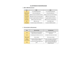
  • 1. ALL DIFFERENCES IN MICROPROCESSOR 1. 8085 vs 8086 Microprocessor Base 8085 8086 Size It is a 8-bit Microprocessor It is a 16-bit Microprocessor Address Bus It has 16-bit address bus It has 20-bit address bus Memory 8085 can access up to 64kb of memory 8086 can access up to 1mb of memory Instruction 8085 doesn’t have an instruction queue 8086 has an instruction queue Pipeline It doesn’t supports pipeline architecture It supports pipeline architecture I/O access 8085 can access 2^8= 256 I/O’s 8086 can access 2^16=65,536 I/O’s Cost 8085 cost is low Cost of 8086 is high Transistors It consists of approx. 6500 transistors It consists of 29000 transistors 2. Microcontroller vs Microprocessor Base Microcontroller Microprocessor Uses Microcontroller are used to execute a single task within an application Microprocessor are used for big applications Cost Its designing and hardware cost is low Its design and hardware cost is high Replaceable Easy to replace Not so easy to replace Power Consumption It is built with CMOS technology, which require less power to operate. The power consumption is high because it has to control the entire system. Parts It consists of CPU, RAM, ROM and I/O ports. It doesn’t consists of RAM, ROM, I/O ports. It uses its pins to interface to peripheral devices.
  • 2. 3. Memory Mapped I/O vs I/O Mapped I/O Base Memory Mapped I/O I/O Mapped I/O Basic I/O devices are treated as memory I/O devices are treated as I/O devices. Allotted Address Size 16-bit (A0-A15) 8-bit (A0-A7) Data Transfer Instruction Same for memory and I/O devices Different for memory and I/O devices Cycles Involved Memory read and Memory Write I/O read and I/O write Interfacing I/O ports Large (around 64k) Comparatively small (around 256) Efficiency Less Comparatively more Data Movement Between registers and ports Between accumulator and ports. Example instruction LDA ****H MOV A,M IN ****H OUT ****H 4. CSIC vs RISC Processor Base RISC CISC Basic RISC is a reduced instruction set. CISC is a complex instruction set. Instruction The number of instructions is less as compared to CISC. The number of instructions is more as compared to RISC. Addressing mode The addressing modes are less. The addressing modes are more. Instruction format It works in a fixed instruction format. It works in a variable instruction format. Power consumption The RISC consumes low power. The CISC consumes high power. pipeline The RISC processors are highly pipelined. The CISC processors are less pipelined. Optimization process It optimizes the performance by focusing on software. It optimizes the performance by focusing on hardware. RAM Requires more RAM. Requires less RAM.
  • 3. 5. SIM instruction vs RIM instruction Base Sim Instruction Rim Instruction Basic SIM stands for Set Interrupt Mask. RIM stands for Read Interrupt Mask. Job It is responsible for masking/unmasking of RST 7.5, RST 6.5 and RST 5.5. It checks whether RST 7.5, RST 6.5, RST 5.5 are masked or not. Working Process It resets to 0 RST 7.5 flip flop. It checks whether interrupts are enabled or not and whether RST 7.5, RST 6.5 or RST 5.5 interrupts are pending or not. Accumulator Value The content of the Accumulator decides the action to be taken. So before executing the SIM instruction, it is mandatory to initialize Accumulator with the required value. The contents of the Accumulator after the execution of the RIM instruction provide this information. Thus, it is essential to look into the Accumulator contents after the RIM instruction is executed. Uses SIM instruction can be used for serial output of data. RIM instruction can be used for serial input of data. Opcode Its opcode (in Hex) is 30. Its opcode (in Hex) is 20. 6. Software Interrupt vs Hardware Interrupt Base Hardware Interrupt Software Interrupt Definition Hardware interrupt is an interrupt generated from an external device or hardware. Software interrupt is the interrupt that is generated by any internal system of the computer. Program Counter It do not increment the program counter. It increment the program counter. Priority It has lowest priority than software interrupts It has highest priority among all interrupts. Event Type It is an asynchronous event. It is synchronous event. Classification Hardware interrupts can be classified into two types they are: 1. Maskable Interrupt. 2. Non-Maskable Interrupt. Software interrupts can be classified into two types they are: 1. Normal Interrupts. 2. Exception Example Keystroke depressions and mouse movements are examples of hardware interrupt. All system calls are examples of software interrupts
  • 4. 7. 8253 vs 8254 - Programmable Interval Timer Base 8253 8254 Frequency Its operating frequency is 0 - 2.6 MHz Its operating frequency is 0 - 10 MHz Technology It uses N-MOS technology It uses H-MOS technology Read-Back command Read-Back command is not available Read-Back command is available interleaved Reads and writes of the same counter cannot be interleaved. Reads and writes of the same counter can be interleaved. 8. PROM vs EPROM Parameters PROM EPROM Full Form Programmable Read-Only Memory. Erasable Programmable Read-Only Memory. Reuse It is not reusable in any way. We can only write/feed content ONCE on a PROM. It is reusable. We can rewrite/erase the content present on an EPROM easily. Cost Efficiency It is more cost-efficient and comparatively inexpensive as compared to EPROM. It is less cost-efficient and comparatively costlier as compared to PROM. Reversibility PROM has a permanent memory thus the process is irreversible. We can reverse the storage process of EPROM since the memory isn’t permanent at all. Storage Endurance It has a very high storage endurance. It has a comparatively lower storage endurance. It is easily affected by radiation and electrical noise. Type It is a read-only type of memory storage system. It can be both written and read optically. Version It is the older and outdated version of EPROM. It is the newer and updated version of PROM. Scalability and Flexibility It is MORE scalable and flexible. It is LESS scalable and flexible. Constructing Material We use bipolar transistors in the construction of PROM. We use MOS transistors in the construction of PROM.
  • 5. 9. PIN Diagram of 8085 microprocessor.
  • 6. [1]  TRAP & HOLD which interrupt has the highest priority and why? TRAP has the highest priority in all interrupts. Because, TRAP cannot be masked but it can be delayed using HOLD signal. This interrupt transfers the microprocessor’s control to location 0024H.  Explain the need to de-multiplex the bus AD7-AD0. [1] As AD7-AD0 lines serve a dual purpose they have to be demultiplexed to get all the information. The address’s high order bits remain on the bus for 3 clock period. The low order bits remain for only 1 clock period and may be lost if they are not save externally.  What is multiplexing in 8085? [2] The data and the lower order address bus on the 8085 microprocessor are multiplexed with each other. Multiplexing is used to reduce the number of pins of 8085, which otherwise would have been a 48 pin chip. But because of multiplexing, external hardware is required to demultiplex the lower byte address cum data bus.  What is Instruction register in 8085 MP? [2] o The Instruction Register (IR) is another internal component of the 8085 microprocessor. o It is a special register that holds the instruction currently being executed. The instruction is fetched from memory and loaded into the IR, where it is decoded and executed. o The IR acts as a buffer between the memory and the control unit, which interprets the instruction and generates the necessary control signals to execute it. o This way the IR holds the instruction and makes sure that the instruction is executed correctly and in the correct order.  How Ready signal is used in microprocessor. [2] o This signal is sent by an input or output device to the microprocessor. o Ready signal indicates that the input or output device is ready to send or receive data. o A slow input or output device is connected to the microprocessor through ready line. When Ready is HIGH, it indicates the input/output device is ready to send/receive data When Ready is LOW, microprocessor will wait until ‘Ready’ becomes high.  Explain how a microprocessor differentiates positive and negative number. [2] Microprocessor normally cannot isolate positive and negative number. It can only represent the bit pattern of given numbers. Here, the left most or most significant bit is the sign bit. It tells the microprocessor about the sign of that number. If the MSB is 0 then, the given number is positive and if 1 then it’s a negative number.  Discuss instruction cycle, machine cycle, and T-state. [2] o Instruction Cycle: The time required to execute an instruction is called an instruction cycle. o Machine Cycle: The time required to access the memory or I/O devices is called machine cycle. o T-States: Instruction and Machine cycle takes multiple clock period. The portion of an operation is carried out in one system clock period, is called as T-states.
  • 7.  Mention all the ports present in 8255 [2] 8255A has three ports, i.e. PORT A, PORT B AND PORT C. o PORT A: Contains one 8-bit output latch/buffer and one 8-bit input buffer. o PORT B: Similar as PORT-A. o PORT C: Can be split in 2 parts, i.e. PORT-C lower (PC0-PC3) & PORT-C Upper (PC4-PC7) by the control word.  What is cache controller? [2] o Define: The cache controller is a hardware the copies code or data from main memory to cache memory automatically. o Uses: It performs this task automatically to concate cache operation from the software it supports.  What Happens when RET instruction is executed? [2] o RET Stands for ‘Return from Subroutine’. o It is a one byte instruction. o After the execution of this program, it transfer the control back to the main program where it has stopped. o It transfer program control to a return address located on the top of the stack. The address is manually placed on the stack by a CALL instruction. o The return address is popped from the top of the stack into the program counter.  What are HOLD and HLDA? [2] o When another device of the computer system requires address and data buses for fata transfer. It sends HOLD signal to the microprocessor. o After receiving the HOLD request, the microprocessor sends out a HLDA (HOLD Acknowledgment) signal to the device.  How are they used? [2] o When microprocessor receive ‘HOLD’ signal it leaves the control over the buses as soon as the current machine cycle is completed, internal processing may continue. o After the removal of HOLD signal, the HLDA goes low and thereafter the microprocessor takes the control back over the buses.  How address bus and data bus are separated in 8085 MP. [4] In the 8085 microprocessor, the address bus and data bus are physically separated and serve different functions.  The address bus is used to transmit the memory address of the location where the data is to be stored or retrieved. It is a 16-bit bus, allowing the 8085 to address up to 64KB of memory.  The data bus, on the other hand, is used to transmit the actual data between the microprocessor and memory or input/output devices. It is an 8-bit bus, allowing the 8085 to process 8-bit data at a time. The internal components of the 8085 microprocessor such as ALU, IR and registers are connected to both address and data bus. The separation of the address bus and data bus allows for efficient communication between the microprocessor and memory or input/output devices, and enables the microprocessor to process both memory addresses and data simultaneously.
  • 8.  Instructions and their required Machine Cycles in 8085  Give the bit configuration of 8085 flag register. [4] 1. A flag is a single bit status register (Flip-Flop). 2. Flags are either set or reset by ALU according to the result by ALU. 3. Flags are important because they are the conditions for conditional branching instructions. 4. 8085 has five flags. Sign flag, Zero flag, Auxiliary Carry flag, Parity flag and Carry flag. An 8-bit register is used to represent five flags as shown in the following figure  Explain the working procedure of DCR and DAD with examples. [4] The working procedure of DCR (Decrement Register) and DAD (Double Add) instruction in the 8085 Microprocessor is as follows: o DCR (Decrement Register):  It is a 1-byte instruction that decrements the contents of a specified register or memory location by 1.  The instruction format is "DCR R" where R can be any register from B, C, D, E, H, or L.  For example, "DCR B" will decrement the contents of register B by 1.  The operation performed by DCR is similar to the following expression: R = R - 1 o DAD (Double Add):  It is a 2-byte instruction that adds the contents of two specified register pairs (B and D, or H and L) and stores the result in the H register.  The instruction format is "DAD H" or "DAD B".  For example, "DAD H" will add the contents of register pair H-L and store the result in H.  The operation performed by DAD is similar to the following expression: H = H + L + carry.  The carry flag is updated based on the result of the addition. S.No Instruction No. of MC’S MC-1 MC-2 MC-3 MC-4 1 MOV A,B 1 OF - - - 2 MVI A,06H 2 OF MR - - 3 LXI H,4050H 3 OF MR MR - 4 INR M 3 OF MR MW - 5 LDA 5000H 4 OF MR MR MR 6 STA 3050H 4 OF MR MR MW 7 IN 80H 3 OF MR IOR - 8 OUT 80h 3 OF MR IOW -
  • 9.  NOP instruction and its utility. [4] o NOP (No Operation) Instruction:  NOP is a 1-byte instruction in the 8085 Microprocessor that does not perform any operation.  The instruction format is simply "NOP".  When the 8085 fetches and executes a NOP instruction, it simply increments the program counter and fetches the next instruction.  NOP does not affect the contents of any register or memory location. o Utility of NOP Instruction:  NOP is often used as a placeholder or dummy instruction in the program.  It can be used to fill the unused space in the program, where the programmer may want to insert some instructions later.  NOP can be used to insert a delay in the program. For example, when waiting for a slower device to complete an operation, NOP instructions can be used to fill the time.  NOP can also be used to align the code in certain systems where instructions must start at specific addresses. In conclusion, NOP is a dummy instruction that does not perform any operation. It is used in various ways, such as a placeholder, to insert delays, align code, or measure system performance.  Interrupts in 8085 [4/5] Interrupts are the signals generated by the external devices to request the microprocessor to perform a task. There are 5 interrupt signals, i.e. TRAP, RST 7.5, RST 6.5, RST 5.5, and INTR.Interrupt are classified into following groups based on their parameter − o Vector interrupt − In this type of interrupt, the interrupt address is known to the processor. For example: RST7.5, RST6.5, RST5.5, TRAP. o Non-Vector interrupt − In this type of interrupt, the interrupt address is not known to the processor so, the interrupt address needs to be sent externally by the device to perform interrupts. For example: INTR. o Maskable interrupt − In this type of interrupt, we can disable the interrupt by writing some instructions into the program. For example: RST7.5, RST6.5, RST5.5. o Non-Maskable interrupt − In this type of interrupt, we cannot disable the interrupt by writing some instructions into the program. For example: TRAP. o Software interrupt − In this type of interrupt, the programmer has to add the instructions into the program to execute the interrupt. There are 8 software interrupts in 8085, i.e. RST0, RST1, RST2, RST3, RST4, RST5, RST6, and RST7. o Hardware interrupt − There are 5 interrupt pins in 8085 used as hardware interrupts, i.e. TRAP, RST7.5, RST6.5, RST5.5, INTA.