2. environment through tubular specimens or to move it rapidly
past the plane face of a corrosion coupon (2). Alternatively, the
coupon may be rotated through the environment, although it is
then difficult to evaluate the velocity quantitatively because of
the stirring effects incurred.
4.1.3 The behavior of certain metals and alloys may be
profoundly influenced by the presence of dissolved oxygen. If
this is a factor to be considered in a specific test, the solution
should be completely aerated or deaerated in accordance with
8.7.
4.1.4 In some cases, the rate of corrosion may be governed
by other minor constituents in the solution, in which case they
will have to be continually or intermittently replenished by
changing the solution in the test.
4.1.5 Corrosion products may have undesirable effects on a
chemical product. The amount of possible contamination can
be estimated from the loss in mass of the specimen, with proper
application of the expected relationships among (1) the area of
corroding surface, (2) the mass of the chemical product
handled, and (3) the duration of contact of a unit of mass of the
chemical product with the corroding surface.
4.1.6 Corrosion products from the coupon may influence the
corrosion rate of the metal itself or of different metals exposed
at the same time. For example, the accumulation of cupric ions
in the testing of copper alloys in intermediate strengths of
sulfuric acid will accelerate the corrosion of copper alloys, as
compared to the rates that would be obtained if the corrosion
products were continually removed. Cupric ions may also
exhibit a passivating effect upon stainless steel coupons ex-
posed at the same time. In practice, only alloys of the same
general type should be exposed in the testing apparatus.
4.1.7 Coupon corrosion testing is predominantly designed
to investigate general corrosion. There are a number of other
special types of phenomena of which one must be aware in the
design and interpretation of corrosion tests.
4.1.7.1 Galvanic corrosion may be investigated by special
devices which couple one coupon to another in electrical
contact. The behavior of the specimens in this galvanic couple
are compared with that of insulated specimens exposed on the
same holder and the galvanic effects noted. It should be
observed, however, that galvanic corrosion can be greatly
affected by the area ratios of the respective metals, the distance
between the metals and the resistivity of the electrolyte. The
coupling of corrosion coupons then yields only qualitative
results, as a particular coupon reflects only the relationship
between these two metals at the particular area ratio involved.
4.1.7.2 Crevice corrosion or concentration cell corrosion
may occur where the metal surface is partially blocked from
the corroding liquid as under a spacer or supporting hook. It is
necessary to evaluate this localized corrosion separately from
the overall mass loss.
4.1.7.3 Selective corrosion at the grain boundaries (for
example, intergranular corrosion of sensitized austenitic stain-
less steels) will not be readily observable in mass loss
measurements unless the attack is severe enough to cause grain
dropping, and often requires microscopic examination of the
coupons after exposure.
4.1.7.4 Dealloying or “parting” corrosion is a condition in
which one constituent is selectively removed from an alloy, as
in the dezincification of brass or the graphitization of cast iron.
Close attention and a more sophisticated evaluation than a
simple mass loss measurement are required to detect this
phenomenon.
4.1.7.5 Certain metals and alloys are subject to a highly
localized type of attack called pitting corrosion. This cannot be
evaluated by mass loss alone. The reporting of nonuniform
corrosion is discussed below. It should be appreciated that
pitting is a statistical phenomenon and that the incidence of
pitting may be directly related to the area of metal exposed. For
example, a small coupon is not as prone to exhibit pitting as a
large one and it is possible to miss the phenomenon altogether
in the corrosion testing of certain alloys, such as the AISI Type
300 series stainless steels in chloride contaminated environ-
ments.
4.1.7.6 All metals and alloys are subject to stress-corrosion
cracking under some circumstances. This cracking occurs
under conditions of applied or residual tensile stress, and it
may or may not be visible to the unaided eye or upon casual
inspection. A metallographic examination may confirm the
presence of stress-corrosion cracking. It is imperative to note
that this usually occurs with no significant loss in mass of the
test coupon, although certain refractory metals are an exception
to these observations. Generally, if cracking is observed on the
coupon, it can be taken as positive indication of susceptibility,
whereas failure to effect this phenomenon simply means that it
did not occur under the duration and specific conditions of the
test. Separate and special techniques are employed for the
specific evaluation of the susceptibility of metals and alloys to
stress corrosion cracking (see Ref. (3)).
5. Apparatus
5.1 A versatile and convenient apparatus should be used,
consisting of a kettle or flask of suitable size (usually 500 to
5000 mL), a reflux condenser with atmospheric seal, a sparger
for controlling atmosphere or aeration, a thermowell and
temperature-regulating device, a heating device (mantle, hot
plate, or bath), and a specimen support system. If agitation is
required, the apparatus can be modified to accept a suitable
stirring mechanism, such as a magnetic stirrer. A typical resin
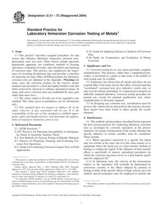
flask setup for this type test is shown in Fig. 1.
5.2 The suggested components can be modified, simplified,
or made more sophisticated to fit the needs of a particular
investigation. The suggested apparatus is basic and the appa-
ratus is limited only by the judgment and ingenuity of the
investigator.
5.2.1 A glass reaction kettle can be used where the configu-
ration and size of the specimen will permit entry through the
narrow kettle neck (for example, 45/50 ground-glass joint). For
solutions corrosive to glass, suitable metallic or plastic kettles
may be employed.
5.2.2 In some cases a wide-mouth jar with a suitable closure
is sufficient when simple immersion tests at ambient tempera-
tures are to be investigated.
5.2.3 Open-beaker tests should not be used because of
evaporation and contamination.
G 31 – 72 (2004)
2
3. 5.2.4 In more complex tests, provisions might be needed for
continuous flow or replenishment of the corrosive liquid, while
simultaneously maintaining a controlled atmosphere.
6. Sampling
6.1 The bulk sampling of products is outside the scope of
this practice.
7. Test Specimen
7.1 In laboratory tests, uniform corrosion rates of duplicate
specimens are usually within 610 % under the same test
conditions. Occasional exceptions, in which a large difference
is observed, can occur under conditions of borderline passivity
of metals or alloys that depend on a passive film for their
resistance to corrosion. Therefore, at least duplicate specimens
should normally be exposed in each test.
7.2 If the effects of corrosion are to be determined by
changes in mechanical properties, untested duplicate speci-
mens should be preserved in a noncorrosive environment at the
same temperature as the test environment for comparison with
the corroded specimens. The mechanical property commonly
used for comparison is the tensile strength. Measurement of
percent elongation is a useful index of embrittlement. The
procedures for determining these values are shown in detail in
Test Methods E 8.
7.3 The size and shape of specimens will vary with the
purpose of the test, nature of the materials, and apparatus used.
A large surface-to-mass ratio and a small ratio of edge area to
total area are desirable. These ratios can be achieved through
the use of square or circular specimens of minimum thickness.
Masking may also be used to achieve the desired area ratios but
may cause crevice corrosion problems. Circular specimens
should preferably be cut from sheet and not bar stock, to
minimize the exposed end grain. Special coupons (for example,
sections of welded tubing) may be employed for specific
purposes.
7.3.1 A circular specimen of about 38-mm (1.5-in.) diam-
eter is a convenient shape for laboratory corrosion tests. With
a thickness of approximately 3 mm (0.125-in.) and an 8-mm
(5⁄16-in.) or 11-mm (7⁄16-in.) diameter hole for mounting, these
specimens will readily pass through a 45/50 ground-glass joint
of a distillation kettle. The total surface area of a circular
specimen is given by the following equation:
A 5 p/2~D 2
2 d 2
! 1 tpD 1 tpd (1)
where:
t = thickness,
D = diameter of the specimen, and
d = diameter of the mounting hole.
7.3.1.1 If the hole is completely covered by the mounting
support, the last term (tpd) in the equation is omitted.
7.3.2 Strip coupons 50 by 25 by 1.6 or 3 mm (2 by 1 by 1⁄16
or 1⁄8 in.) may be preferred as corrosion specimens, particularly
if interface or liquid line effects are to be studied by the
laboratory tests (see Fig. 1), but the evaluation of such specific
effects are beyond the scope of this practice.
7.3.3 All specimens should be measured carefully to permit
accurate calculation of the exposed areas. A geometric area
calculation accurate to 61 % is usually adequate.
7.4 More uniform results may be expected if a substantial
layer of metal is removed from the specimens to eliminate
variations in condition of the original metallic surface. This can
be done by chemical treatment (pickling), electrolytic removal,
or by grinding with a coarse abrasive paper or cloth such as No.
50, using care not to work harden the surface (see section 5.7).
At least 0.0025 mm (0.0001 in.) or 0.0155 to 0.0233 mg/mm2
(10 to 15 mg/in.2
) should be removed. (If clad alloy specimens
are to be used, special attention must be given to ensure that
excessive metal is not removed.) After final preparation of the
specimen surface, the specimens should be stored in a desic-
cator until exposure, if they are not used immediately. In
special cases (for example, for aluminum and certain copper
alloys), a minimum of 24 h storage in a desiccator is recom-
mended. The choice of a specific treatment must be considered
on the basis of the alloy to be tested and the reasons for testing.
A commercial surface may sometimes yield the most signifi-
cant results. Too much surface preparation may remove segre-
gated elements, surface contamination, and so forth, and
therefore not be representative.
7.5 Exposure of sheared edges should be avoided unless the
purpose of the test is to study effects of the shearing operation.
It may be desirable to test a surface representative of the
material and metallurgical conditions used in practice.
NOTE 1—The flask can be used as a versatile and convenient apparatus
to conduct simple immersion tests. Configuration of top to flask is such
that more sophisticated apparatus can be added as required by the specific
test being conducted. A = thermowell, B = resin flask, C = specimens hung
on supporting device, D = air inlet, E = heating mantle, F = liquid inter-
face, G = opening in flask for additional apparatus that may be required,
and H = reflux condenser.
FIG. 1 Typical Resin Flask
G 31 – 72 (2004)
3
4. 7.6 The specimen can be stamped with an appropriate
identifying mark. If metallic contamination of the stamped area
may influence the corrosion behavior, chemical cleaning must
be employed to remove any traces of foreign particles from the
surface of the coupon (for example, by immersion of stainless
steel coupons in dilute nitric acid following stamping with steel
dies).
7.6.1 The stamp, besides identifying the specimen, intro-
duces stresses and cold work in the specimen that could be
responsible for localized corrosion or stress-corrosion crack-
ing, or both.
7.6.2 Stress-corrosion cracking at the identifying mark is a
positive indication of susceptibility to such corrosion. How-
ever, the absence of cracking should not be interpreted as
indicating resistance (see 4.1.7.6).
7.7 Final surface treatment of the specimens should include
finishing with No. 120 abrasive paper or cloth or the equiva-
lent, unless the surface is to be used in the mill finished
condition. This resurfacing may cause some surface work
hardening, to an extent which will be determined by the vigor
of the surfacing operation, but is not ordinarily significant. The
surface finish to be encountered in service may be more
appropriate for some testing.
7.7.1 Coupons of different alloy compositions should never
be ground on the same cloth.
7.7.2 Wet grinding should be used on alloys which work
harden quickly, such as the austenitic stainless steels.
7.8 The specimens should be finally degreased by scrubbing
with bleach-free scouring powder, followed by thorough rins-
ing in water and in a suitable solvent (such as acetone,
methanol, or a mixture of 50 % methanol and 50 % ether), and
air dried. For relatively soft metals (such as aluminum,
magnesium, and copper), scrubbing with abrasive powder is
not always needed and can mar the surface of the specimen.
Proper ultrasonic procedures are an acceptable alternate. The
use of towels for drying may introduce an error through
contamination of the specimens with grease or lint.
7.9 The dried specimens should be weighed on an analytical
balance to an accuracy of at least 60.5 mg. If cleaning deposits
(for example, scouring powder) remain or lack of complete
dryness is suspected, then recleaning and drying is performed
until a constant mass is attained.
7.10 The method of specimen preparation should be de-
scribed when reporting test results, to facilitate interpretation
of data by other persons.
7.11 The use of welded specimens is sometimes desirable,
because some welds may be cathodic or anodic to the parent
metal and may affect the corrosion rate.
7.11.1 The heat-affected zone is also of importance but
should be studied separately, because welds on coupons do not
faithfully reproduce heat input or size effects of full-size
weldments.
7.11.2 Corrosion of a welded coupon is best reported by
description and thickness measurements rather than a millime-
tre per year (mils per year) rate, because the attack is normally
localized and not representative of the entire surface.
7.11.3 A complete discussion of corrosion testing of welded
coupons or the effect of heat treatment on the corrosion
resistance of a metal is not within the scope of this practice.
8. Test Conditions
8.1 Selection of the conditions for a laboratory corrosion
test will be determined by the purpose of the test.
8.1.1 If the test is to be a guide for the selection of a material
for a particular purpose, the limits of the controlling factors in
service must be determined. These factors include oxygen
concentration, temperature, rate of flow, pH value, composi-
tion, and other important characteristics of the solution.
8.2 An effort should be made to duplicate all pertinent
service conditions in the corrosion test.
8.3 It is important that test conditions be controlled through-
out the test in order to ensure reproducible results.
8.4 The spread in corrosion rate values for duplicate speci-
mens in a given test probably should not exceed 610 % of the
average when the attack is uniform.
8.5 Composition of Solution:
8.5.1 Test solutions should be prepared accurately from
chemicals conforming to the Specifications of the Committee
on Analytical Reagents of the American Chemical Society5
and
distilled water, except in those cases where naturally occurring
solutions or those taken directly from some plant process are
used.
8.5.2 The composition of the test solutions should be
controlled to the fullest extent possible and should be described
as completely and as accurately as possible when the results are
reported.
8.5.2.1 Minor constituents should not be overlooked be-
cause they often affect corrosion rates.
8.5.2.2 Chemical content should be reported as percentage
by weight of the solutions. Molarity and normality are also
helpful in defining the concentration of chemicals in some test
solutions.
8.5.3 If problems are suspected, the composition of the test
solutions should be checked by analysis at the end of the test
to determine the extent of change in composition, such as
might result from evaporation or depletion.
8.5.4 Evaporation losses may be controlled by a constant
level device or by frequent addition of appropriate solution to
maintain the original volume within 61 %. Preferably, the use
of a reflux condenser ordinarily precludes the necessity of
adding to the original kettle charge.
8.5.5 In some cases, composition of the test solution may
change as a result of catalytic decomposition or by reaction
with the test coupons. These changes should be determined if
possible. Where required, the exhausted constituents should be
added or a fresh solution provided during the course of the test.
8.5.6 When possible, only one type of metal should be
exposed in a given test (see 4.1.6).
5
Reagent Chemicals, American Chemical Society Specifications, American
Chemical Society, Washington, DC. For suggestions on the testing of reagents not
listed by the American Chemical Society, see Analar Standards for Laboratory
Chemicals, BDH Ltd., Poole, Dorset, U.K., and the United States Pharmacopeia
and National Formulary, U.S. Pharmacopeial Convention, Inc. (USPC), Rockville,
MD.
G 31 – 72 (2004)
4
5. 8.6 Temperature of Solution:
8.6.1 Temperature of the corroding solution should be
controlled within 61°C (61.8°F) and must be stated in the
report of test results.
8.6.2 If no specific temperature, such as boiling point, is
required or if a temperature range is to be investigated, the
selected temperatures used in the test, and their respective
duration, must be reported.
8.6.3 For tests at ambient temperature, the tests should be
conducted at the highest temperature anticipated for stagnant
storage in summer months. This temperature may be as high as
from 40 to 45°C (104 to 113°F) in some areas. The variation in
temperature should be reported also (for example, 40 6 2°C).
8.7 Aeration of Solution:
8.7.1 Unless specified, the solution should not be aerated.
Most tests related to process equipment should be run with the
natural atmosphere inherent in the process, such as the vapors
of the boiling liquid.
8.7.2 If aeration is employed, the specimen should not be
located in the direct air stream from the sparger. Extraneous
effects can be encountered if the air stream impinges on the
specimens.
8.7.3 If exclusion of dissolved oxygen is necessary, specific
techniques are required, such as prior heating of the solution
and sparging with an inert gas (usually nitrogen). A liquid
atmospheric seal is required on the test vessel to prevent further
contamination.
8.7.4 If oxygen saturation of the test solution is desired, this
can best be achieved by sparging with oxygen. For other
degrees of aeration, the solution should be sparaged with air or
synthetic mixtures of air or oxygen with an inert gas. Oxygen
saturation is a function of the partial pressure of oxygen in the
gas.
8.8 Solution Velocity:
8.8.1 The effect of velocity is not usually determined in
normal laboratory tests, although specific tests have been
designed for this purpose.
8.8.2 Tests at the boiling point should be conducted with the
minimum possible heat input, and boiling chips should be used
to avoid excessive turbulence and bubble impingement.
8.8.3 In tests below the boiling point, thermal convection
generally is the only source of liquid velocity.
8.8.4 In test solutions with high viscosity, supplemental
controlled stirring with a magnetic stirrer is recommended.
8.9 Volume of Test Solution:
8.9.1 The volume of the test solution should be large enough
to avoid any appreciable change in its corrosivity during the
test, either through exhaustion of corrosive constituents or by
accumulation of corrosion products that might affect further
corrosion.
8.9.2 Two examples of a minimum “solution volume-
tospecimen area” ratio are 0.20 mL/mm2
(125 mL/in.2
) of
specimen surface (Practice A 262), and 0.40 mL/mm 2
(250
mL/in.2
).
8.9.3 When the test objective is to determine the effect of a
metal or alloy on the characteristics of the test solution (for
example, to determine the effects of metals on dyes), it is
desirable to reproduce the ratio of solution volume to exposed
metal surface that exists in practice. The actual time of contact
of the metal with the solution must also be taken into account.
Any necessary distortion of the test conditions must be
considered when interpreting the results.
8.10 Method of Supporting Specimens:
8.10.1 The supporting device and container should not be
affected by or cause contamination of the test solution.
8.10.2 The method of supporting specimens will vary with
the apparatus used for conducting the test, but should be
designed to insulate the specimens from each other physically
and electrically and to insulate the specimens from any metallic
container or supporting device used within the apparatus.
8.10.3 Shape and form of the specimen support should
assure free contact of the specimen with the corroding solution,
the liquid line, or the vapor phase as shown in Fig. 1. If clad
alloys are exposed, special procedures will be required to
ensure that only the cladding is exposed, unless the purpose is
to test the ability of the cladding to protect cut edges in the test
solution.
8.10.4 Some common supports are glass or ceramic rods,
glass saddles, glass hooks, fluorocarbon plastic strings, and
various insulated or coated metallic supports.
8.11 Duration of Test:
8.11.1 Although duration of any test will be determined by
the nature and purpose of the test, an excellent procedure for
evaluating the effect of time on corrosion of the metal and also
on the corrosiveness of the environment in laboratory tests has
been presented by Wachter and Treseder (4). This technique is
called the “planned interval test,” and the procedure and
evaluation of results are given in Table 1. Other procedures that
require the removal of solid corrosion products between
exposure periods will not measure accurately the normal
changes of corrosion with time.
8.11.2 Materials that experience severe corrosion generally
do not ordinarily need lengthy tests to obtain accurate corro-
sion rates. However, there are cases where this assumption is
not valid. For example, lead exposed to sulfuric acid corrodes
at an extremely high rate at first, while building a protective
film; then the rates decrease considerably so that further
corrosion is negligible. The phenomenon of forming a protec-
tive film is observed with many corrosion-resistant materials.
Therefore, short tests on such materials would indicate a high
corrosion rate and be completely misleading.
8.11.3 Short-time tests also can give misleading results on
alloys that form passive films, such as stainless steels. With
borderline conditions, a prolonged test may be needed to
permit breakdown of the passive film and subsequent more
rapid attack. Consequently, tests run for long periods are
considerably more realistic than those conducted for short
durations. This statement must be qualified by stating that
corrosion should not proceed to the point where the original
specimen size or the exposed area is drastically reduced or
where the metal is perforated.
8.11.4 If anticipated corrosion rates are moderate or low, the
following equation gives the suggested test duration:
Hours 5 2000/~corrosion rate in mpy! (2)
G 31 – 72 (2004)
5
6. where mpy = mils per year (see 11.2.1 and Note 1 for
conversion to other units).
8.11.4.1 Example—Where the corrosion rate is 0.25 mm/y
(10 mpy), the test should run for at least 200 h.
8.11.4.2 This method of estimating test duration is useful
only as an aid in deciding, after a test has been made, whether
or not it is desirable to repeat the test for a longer period. The
most common testing periods are 48 to 168 h (2 to 7 days).
8.11.5 In some cases, it may be necessary to know the
degree of contamination caused by the products of corrosion.
This can be accomplished by analysis of the solution after
corrosion has occurred. The corrosion rate can be calculated
from the concentration of the matrix metal found in the
solution and it can be compared to that determined from the
mass loss of the specimens. However, some of the corrosion
products usually adhere to the specimen as a scale and the
corrosion rate calculated from the metal content in the solution
is not always correct.
8.12 The design of corrosion testing programs is further
discussed in Guide G 16.
9. Methods of Cleaning Specimens after Test
9.1 Before specimens are cleaned, their appearance should
be observed and recorded. Location of deposits, variations in
types of deposits, or variations in corrosion products are
extremely important in evaluating localized corrosion, such as
pitting and concentration cell attack.
9.2 Cleaning specimens after the test is a vital step in the
corrosion test procedure and if not done properly, can cause
misleading results.
9.2.1 Generally, the cleaning procedure should remove all
corrosion products from specimens with a minimum removal
of sound metal.
9.2.2 Set rules cannot be applied to specimen cleaning,
because procedures will vary, depending on the type of metal
being cleaned and on the degree of adherence of corrosion
products.
9.3 Cleaning methods can be divided into three general
categories: mechanical, chemical, and electrolytic.
9.3.1 Mechanical cleaning includes scrubbing, scraping,
brushing, mechanical shocking, and ultrasonic procedures.
Scrubbing with a bristle brush and mild abrasive is the most
popular of these methods. The others are used principally as a
supplement to remove heavily encrusted corrosion products
before scrubbing. Care should be used to avoid the removal of
sound metal.
9.3.2 Chemical cleaning implies the removal of material
from the surface of the specimen by dissolution in an appro-
priate chemical solution. Solvents such as acetone, carbon
tetrachloride, and alcohol are used to remove oil, grease, or
resin and are usually applied prior to other methods of
cleaning. Chemicals are chosen for application to a specific
material. Methods for chemical cleaning after testing of spe-
cific metals and alloys are described in Practice G 1.
9.3.3 Electrolytic cleaning should be preceded by scrubbing
to remove loosely adhering corrosion products. A method of
electrolytic cleaning is described in Practice G 1.
9.3.3.1 Precautions must be taken to ensure good electrical
contact with the specimen, to avoid contamination of the
solution with easily reducible metal ions, and to ensure that
inhibitor decomposition has not occurred.
9.4 Whatever treatment is used to clean specimens after a
corrosion test, its effect in removing metal should be deter-
mined and the mass loss should be corrected accordingly. A
“blank” specimen should be weighed before and after exposure
to the cleaning procedure to establish this mass loss (see also
Practice G 1). Careful observation is needed to ensure that
pitting does not occur during cleaning.
9.4.1 Following removal of all scale, the specimen should
be treated as discussed in 5.8.
9.4.2 The description of the cleaning method should be
included with the data reported.
10. Interpretation of Results
10.1 After corroded specimens have been cleaned, they
should be reweighed with an accuracy corresponding to that of
the original weighing. The mass loss during the test period can
be used as the principal measure of corrosion.
TABLE 1 Planned Interval Corrosion Test
(Reprinted by permission from Chemical Engineering Progress, June
1947)
Identical specimens all placed in the same corrosive fluid. Imposed
conditions of the test kept constant for entire time t + 1. Letters, A1, A
t, At+1, B, represent corrosion damage experienced by each test
specimen. A2 is calculated by subtracting Atfrom At+1.
Occurrences During Corrosion Test Criteria
Liquid corrosiveness unchanged
decreased
increased
A1 = B
B < A1
A1 < B
Metal corrodibility unchanged
decreased
increased
A2 = B
A2 < B
B < A2
Combinations of Situations
Liquid corrosiveness Metal corrodibility Criteria
1. unchanged unchanged A1 = A2 = B
2. unchanged decreased A2 < A1 = B
3. unchanged increased A1 = B < A2
4. decreased unchanged A2 = B < A1
5. decreased decreased A2 < B < A1
6. decreased increased A1 > B < A2
7. increased unchanged A1 < A2 = B
8. increased decreased A1 < B > A2
9. increased increased A1 < B < A2
Example; Conditions: Duplicate strips of low-carbon steel, each 19 by 76 mm
(3⁄4 by 3 in.), immersed in 200 mL of 10 % AlCl3-90 % SbCl3 mixture through
which dried HCl gas was slowly bubbled at atmospheric pressure. Temperature
90°C.
Interval,
days
Mass Loss,
mg
Penetration,
mm (mils)
Apparent
Corrosion
Rate, mm/y
(mpy)
A1 0–1 1080 .043 (1.69) 15.7 (620)
At 0–3 1430 .057 (2.24) 6.9 (270)
At+1 0–4 1460 .058 (2.29) 5.3 (210)
B 3–4 70 .003 (0.11) 1.0 (40)
A2 calc. 3–4 30 .001 (0.05) 0.5 (18)
Example: A2 < B < A1
.001 < .003 < .043 (0.05 < 0.11 < 1.69)
Therefore, liquid markedly decreased in corrosiveness during test, and formation
of partially protective scale on the steel was indicated.
G 31 – 72 (2004)
6
7. 10.2 After the specimens have been reweighed, they should
be examined carefully for the presence of any pits. If there are
any pits, the average and maximum depths of pits are deter-
mined with a pit gage or a calibrated microscope which can be
focused first on the edges and then on the bottoms of the pits.
The degree of lateral spreading of pits may also be noted.
10.2.1 Pit depths should be reported in millimetres or
thousandths of an inch for the test period and not interpolated
or extrapolated to millimetres per year, thousandths of an inch
per year, or any other arbitrary period because rarely, if ever, is
the rate of initiation or propagation of pits uniform.
10.2.2 The size, shape, and distribution of pits should be
noted. A distinction should be made between those occurring
underneath the supporting devices (concentration cells) and
those on the surfaces that were freely exposed to the test
solution (see Guide G 46).
10.3 If the material being tested is suspected of being
subject to dealloying forms of corrosion such as dezincification
or to intergranular attack, a cross section of the specimen
should be microscopically examined for evidence of such
attack.
10.4 The specimen may be subjected to simple bending tests
to determine whether any embrittlement attack has occurred.
10.5 It may be desirable to make quantitative mechanical
tests, comparing the exposed specimens with uncorroded
specimens reserved for the purpose, as described in 7.2.
11. Calculating Corrosion Rates
11.1 Calculating corrosion rates requires several pieces of
information and several assumptions:
11.1.1 The use of corrosion rates implies that all mass loss
has been due to general corrosion and not to localized
corrosion, such as pitting or intergranular corrosion of sensi-
tized areas on welded coupons. Localized corrosion is reported
separately.
11.1.2 The use of corrosion rates also implies that the
material has not been internally attacked as by dezincification
or intergranular corrosion.
11.1.3 Internal attack can be expressed as a corrosion rate if
desired. However, the calculations must not be based on mass
loss (except in qualification tests such as Practices A 262),
which is usually small but on microsections which show depth
of attack.
11.2 Assuming that localized or internal corrosion is not
present or is recorded separately in the report, the average
corrosion rate can be calculated by the following equation:
Corrosion rate 5 ~K 3 W!/~A 3 T 3 D! (3)
where:
K = a constant (see below)
T = time of exposure in hours to the nearest 0.01 h,
A = area in cm2
to the nearest 0.01 cm2
,
W = mass loss in g, to nearest 1 mg (corrected for any loss
during cleaning (see 9.4)), and
D = density in g/cm3
, (see Appendix X1 of Practice G 1).
11.2.1 Many different units are used to express corrosion
rates. Using the above units for T, A, W, and D, the corrosion
rate can be calculated in a variety of units with the following
appropriate value of K:
Corrosion Rate Units Desired
Constant (K) in Corrosion
Rate Equation
mils per year (mpy) 3.45 3 106
inches per year (ipy) 3.45 3 103
inches per month (ipm) 2.87 3 102
millimetres per year (mm/y) 8.76 3 104
micrometres per year (µm/y) 8.76 3 107
picometres per second (pm/s) 2.78 3 106
grams per square metre per hour (g/m2
·h) 1.00 3 104
3 DA
milligrams per square decimetre per day (mdd) 2.40 3 106
3 DA
micrograms per square metre per second (µg/
m2
·s)
2.78 3 106
3 DA
___________
A
Density is not needed to calculate the corrosion rate in these units. The density
in the constant K cancels out the density in the corrosion rate equation.
NOTE 1—If desired, these constants may also be used to convert
corrosion rates from one set of units to another. To convert a corrosion rate
in units X to a rate of units Y, multiply by KY/KX for example:
15 mpy 5 15 3 [~2.78 3 10 6
!/~~3.45 3 106
!#pm/s
5 12.1 pm/s (4)
12. Report
12.1 The importance of reporting all data as completely as
possible cannot be overemphasized.
12.2 Expansion of the testing program in the future or
correlating the results with tests of other investigators will be
possible only if all pertinent information is properly recorded.
12.3 The following checklist is a recommended guide for
reporting all important information and data.
12.3.1 Corrosive media and concentration (any changes
during test).
12.3.2 Volume of test solution.
12.3.3 Temperature (maximum, minimum, average).
12.3.4 Aeration (describe conditions or technique).
12.3.5 Agitation (describe conditions or technique).
12.3.6 Type of apparatus used for test.
12.3.7 Duration of each test.
12.3.8 Chemical composition or trade name of metals
tested.
12.3.9 Form and metallurgical conditions of specimens.
12.3.10 Exact size, shape, and area of specimens.
12.3.11 Treatment used to prepare specimens for test.
12.3.12 Number of specimens of each material tested, and
whether specimens were tested separately or which specimens
tested in the same container.
12.3.13 Method used to clean specimens after exposure and
the extent of any error expected by this treatment.
12.3.14 Initial and final masses and actual mass losses for
each specimen.
12.3.15 Evaluation of attack if other than general, such as
crevice corrosion under support rod, pit depth and distribution,
and results of microscopical examination or bend tests.
12.3.16 Corrosion rates for each specimen.
G 31 – 72 (2004)
7
8. 12.4 Minor occurrences or deviations from the proposed test
program often can have significant effects and should be
reported if known.
12.5 Statistics can be a valuable tool for analyzing the
results from test programs designed to generate adequate data.
Excellent references for the use of statistics in corrosion studies
include Ref. (5-7) and in Guide G 16.
13. Keywords
13.1 accelerated; immersion; laboratory; mass loss; metals;
pitting
REFERENCES
(1) Fisher, A. O., and Whitney, Jr., F. L., “Laboratory Methods for
Determining Corrosion Rates Under Heat Flux Conditions,” Corro-
sion, Vol 15, No. 5, May 1959, p. 257t.
(2) U.S. Patent 3,228,236, 1969.
(3) “Stress Corrosion Test Environments and Test Durations,” Symposium
on Stress Corrosion Testing, ASTM STP 425, ASTM, 1967.
(4) Wachter, A., and Treseder, R. S., “Corrosion Testing Evaluation of
Metals for Process Equipment,” Chemical Engineering Progress, Vol
43, June 1947, pp. 315–326.
(5) Mickley, H. S., Sherwood, T. K., and Reed, C. E. editors, Applied
Mathematics in Chemical Engineering 2nd Edition, McGraw-Hill
Book Co., New York, NY 1957.
(6) Youden, W. J., Experimentation and Measurement, National Science
Teachers Assn., Washington, DC, 1962.
(7) Booth, F. F., and Tucker, G. E. G., “Statistical Distribution of
Endurance in Electrochemical Stress-Corrosion Tests,” Corrosion, Vol
21, No. 5, May 1965, pp. 173–177.
(8) Champion, F. A., Corrosion Testing Procedures, 2nd Edition, John
Wiley & Sons, Inc., New York, NY, 1965.
ASTM International takes no position respecting the validity of any patent rights asserted in connection with any item mentioned
in this standard. Users of this standard are expressly advised that determination of the validity of any such patent rights, and the risk
of infringement of such rights, are entirely their own responsibility.
This standard is subject to revision at any time by the responsible technical committee and must be reviewed every five years and
if not revised, either reapproved or withdrawn. Your comments are invited either for revision of this standard or for additional standards
and should be addressed to ASTM International Headquarters. Your comments will receive careful consideration at a meeting of the
responsible technical committee, which you may attend. If you feel that your comments have not received a fair hearing you should
make your views known to the ASTM Committee on Standards, at the address shown below.
This standard is copyrighted by ASTM International, 100 Barr Harbor Drive, PO Box C700, West Conshohocken, PA 19428-2959,
United States. Individual reprints (single or multiple copies) of this standard may be obtained by contacting ASTM at the above
address or at 610-832-9585 (phone), 610-832-9555 (fax), or service@astm.org (e-mail); or through the ASTM website
(www.astm.org).
G 31 – 72 (2004)
8