SlideShare a Scribd company logo
1 of 7
Download to read offline
ENCIT-2018-0399
COMPARATIVE THERMAL PERFORMANCE OF FLAT PLATE FINS
AND INLINE STRIP FINS HEAT SINKS
William Denner Pires Fonseca
Carlos A. C. Altemani
State University of Campinas, School of Mechanical Engineering - R. Mendeleyev - 200, Campinas - SP - Zip Code 13083-860
fonsecawdp@gmail.com
altemani@fem.unicamp.br
Abstract. Comparative results for the convective thermal resistance of continuous plate fins and inline strip fins heat sinks
are presented based on correlations from the literature for the Nusselt number for the fins of both heat sink configurations.
The purpose of this investigation is to compare the thermal performance of both heat sinks with the same base and fins
height and thickness, under similar forced airflow cooling conditions. The Nusselt number heat transfer correlations from
the literature considered the heat transfer from the fins, but did not include the convection from the bare heat sink base
(not covered by the fins). Thus, this additional heat transfer from the heat sink base was evaluated and included in a
new more realistic model and the results were compared with those from the literature models. The results showed that
when compared to the plate fins heat sinks, the inline strip fins convective heat transfer coefficients were larger enough to
compensate for their reduced heat transfer area, resulting in smaller convective thermal resistances. It was also verified
that the convective thermal resistance decreases with the strip length, due to larger convective heat transfer coefficients
on the fins. When the heat transfer from the heat sinks base was considered, there was an additional reduction of the heat
sinks convective thermal resistance to the cooling fluid.
Keywords: Heat Sinks, Convective Thermal Resistance, Inline Strip Fins, Plate Fins
1. INTRODUCTION
Heat sinks are widely used in electronic equipment, with the purpose to enhance the convective heat transfer from a
component with high heat flux to a forced flow of a cooling fluid (usually ambient air). They must be designed so that
the components temperatures always remain within their reliable limits, as specified by their manufacturer. In spite of
their large use in the electronics industry, the heat sinks thermal characteristics remain a topic of investigation due to their
variety of geometry, size, operating conditions, and also due to distinct design goals (Webb, 2007).
Two of the most investigated heat sink configurations are the parallel plates heat sinks and the aligned strip fins
heat sinks, as indicated in Fig. 1, with the cooling flow parallel to the heat sink base. Along the years, many analytical,
experimental and numerical investigations were performed to obtain the thermal resistance and the head loss of the cooling
flow through the heat sink channels. The cooling fluid is usually the ambient air, mainly due to its availability, handling
facility and the insulating electrical properties. Several analytical investigations were performed for the parallel plates
heat sinks, mostly with laminar flow in the channels and the results were conveniently presented in the form of compact
models, expressed as algebraic equations. Experimental and numerical investigations were also performed for these heat
sinks and all the results have been compared in the literature, considering both laminar and turbulent flow in the heat
sink channels. The strip fins heat sinks have been investigated mostly through experiments and numerical simulations for
both laminar and turbulent flow in the interfin channels, but the results presented in the literature are not as conveniently
grouped in the form of compact models as those for the plate fins.
Heat transfer results for the parallel plates heat sinks were presented for example by Sparrow et al. (1978), Kadle and
Sparrow (1986), Sata et al. (1997), Jonsson and Moshfegh (2001) and Henríquez et al. (2007). These experimental and
numerical investigations took into account the effects of distinct conditions of the flow entrance in the heat sinks, fins
spacing, thickness and height, as well as the interfins cooling flow in the laminar and turbulent regimes.
Considering now inline strip fins heat sinks, the heat transfer was also reported by several investigators. Sparrow
et al. (1977) reported numerical results for laminar flow in the fins channels and indicated that the partition of each fin
into smaller strips reduces the flow and thermal boundary layers growth in each fin strip, thus reducing their convective
thermal resistance. Ozturk and Tari (2008) investigated numerically the cooling of a CPU by means of aligned strip fins
heat sinks, considering the complete computer chassis as the calculation domain. They investigated the effects of the
number of fins and their distribution, the fin material and the base plate thickness. Al-Sallami et al. (2016) reported
William Denner Pires Fonseca and Carlos A. C. Altemani
Comparative Thermal Performance of Flat Plate Fins and Inline Strip Fins Heat Sinks
numerical results for the convective heat transfer from strip fins heat sinks, with inline and staggered arrangement of the
fins. Their results included the effect of perforated fins to enhance the convective heat transfer and indicated that the
staggered arrangement provides larger heat transfer rates from the heat sinks, at the expense of larger pressure losses.
Hong and Cheng (2009) presented numerical results for the convective cooling of water cooled offset strip fins heat sinks
and investigated the effect of the fins geometry on the heat sink performance. They indicated that there is an optimum strip
fin size to minimize the flow pressure drop and that it depends on the heat flux input and the maximum wall temperature.
The numerical investigations, as those reported previously, are useful to predict the heat sink performance from their
detailed information about the flow and temperature fields, for a specific heat sink configuration and operating conditions.
Additional numerical results may also be easily obtained to represent the effects of changes of the heat sink size and op-
erating conditions. Then, a heat sink prototype, considering distinct design purposes, may be selected from the numerical
simulations. The actual thermal behavior of the prototype may then be measured in laboratory experiments.
In order to reduce the number of numerical simulations, they may start from a heat sink configuration selected from
compact thermal models usually expressed by algebraic correlations, as the Nusselt number for the heat sink cooling flow.
These compact models are usually obtained from analytical or approximate solutions to models of the convective heat
transfer and the flow in the heat sink channels. Thus, these models are useful in the first stages of a heat sink thermal
design.
The purpose of the present work is to compare, by means of compact thermal models, the thermal resistance of two
of the most common heat sink configurations: plate fins and inline strip fins, considering the same heat sink base, fins
spacing and thickness. For each fin configuration, initially Nusselt number correlations were obtained from the literature
(Teertstra et al. (1999) and Teertstra et al. (2000)) for the cooling flow forced convection. These correlations considered
only the convective heat transfer from the fins and were originally employed to obtain the thermal resistances from the
heat sinks. The present work included an estimative to the heat transfer from the bare heat sinks base and a new value
for the heat sink thermal resistance was obtained. Thus, the results from the literature and from the modified model were
employed to compare the thermal resistances of both heat sink configurations.
2. COMPACT THERMAL MODELS
Compact thermal models were employed to compare the thermal resistance of two heat sink configurations indicated
in Fig. 1: plate fins and inline strip fins. Forced convection airflow was assumed parallel to the base of both aluminum
heat sinks with the same base dimensions (LxW), fins height (H), thickness (t) and pass (b), as indicated in Tab. 1. For the
inline strip fins, the ratio (S/P) of the slot width (S) to the slot pitch (P) was assumed equal to 0.5 in the present analysis.
(a) Plate fins (b) Inline strip fins
Figure 1: Geometry of the two heat sink configurations
Table 1: Geometric parameters and thermal conductivity.
Parameter Values
L 115 mm
H 49 mm
b 5.7 mm
t 1.25 mm
w 65 mm
k 200 W/m.K
17th Brazilian Congress of Thermal Sciences and Engineering (ENCIT 2018)
November 25th-28th, 2018, Águas de Lindóia, SP, Brazil
2.1 Nusselt number for the plate fins heat sinks
For the plate fin heat sinks, the Nusselt number was obtained from the model developed by Teertstra et al. (2000). They
presented a composite Nusselt number correlation based on the asymptote values for fully developed and for developing
flow in isothermal channels. It was based on the formula presented by Churchill and Usagi (1972), as expressed by:
Nubi = [(Nufd)−3
+ (Nudev)−3
]−1/3
(1)
In Eq. (1), the Nusselt number Nubi is defined by:
Nubi =
qb
k(2LH)(Tw − Ti)
(2)
The Nusselt number Nubi was based on the interfins spacing b and the analysis performed by Teertstra et al. (2000) in
a fins channel considering only the heat transfer from the fins area: A = (2LH). On the right side of Eq. (1), Nufd and
Nudev are respectively the asymptote solutions for the fully developed and for the developing flow Nusselt numbers in
the interfins channel, both based on the temperature difference between the isothermal fins surface (Tw) and the incoming
cooling flow (Ti). They were expressed as:
Nufd =
1
2
RebPr (3)
Nudev = 0.664 RebPr
1
3 1 +
3.65
√
Reb
(4)
In Eqs. (3) and (4), Pr is the cooling fluid Prandtl number and Reb is a modified Reynolds number, defined by:
Reb =
Ub
ν
b
L
(5)
Replacing Eqs. (3) and (4) into Eq. (1), the Nusselt number for ideal isothermal fins may be expressed as in Eq. (6).
Nubi =

 RebPr
2
−3
+ 0.664 RebPr
1
3 1 +
3.65
√
Reb
−3


−1/3
(6)
Assuming plate fins with adiabatic fins tip, their efficiency ηpf may be expresed as in Eq. (7):
ηpf =
tanh 2Nui
kf
k
H
b
H
t
t
2 + 1
2Nui
kf
k
H
b
H
t
t
2 + 1
(7)
The actual convective thermal resistance for plate fins heat sinks may then be expressed as in Eq. (8):
Rth =
b
k(2LH)Nubiηpf
(8)
2.2 Nusselt number for the inline strip fins heat sinks
These heat sinks replace the single plate of a heat sink row by a number of smaller strip fins. They are used due
to a reduction of the thermal boundary layer growth at each strip fin, thus increasing the heat sink average heat transfer
coefficient (Webb, 2007). When compared to the plate fin, the strip fins in a row have however smaller heat transfer
area. These two effects have opposing effects on this heat sink thermal resistance, as compared to the corresponding plate
fin heat sink. The larger average convective coefficient contributes to smaller thermal resistance, but the corresponding
smaller heat transfer area points in the opposite direction. Thus, one main purpose of this work is to compare the thermal
performance of plate fins and strip fins heat sinks. The model for the strip fins heat sinks was based on a second work of
Teertstra et al. (1999), where they considered that the average convective heat transfer coefficient for this heat sink was
limited by a lower bound and an upper bound. The lower bound was associated to a channel length LLB equal to the total
length of all strips in a single row. Due to an approximate geometric expression used for the lower bound length LLB in
the mentioned reference, a small correction to this length was introduced in the present work, so that it was expressed by:
LLB = (L + S) 1 −
S
P
(9)
William Denner Pires Fonseca and Carlos A. C. Altemani
Comparative Thermal Performance of Flat Plate Fins and Inline Strip Fins Heat Sinks
The lower bound modified Reynolds number ReLB, associated to the lower bound length LLB, was related to the
plate fin modified Reynolds number Reb, defined by Eq. (5), as follows:
ReLB =
Reb
1 − S
P 1 + S
L
(10)
A new ideal lower bound Nusselt number Nui,LB, associated to isothermal strip fins, was then evaluated as in Eq. (6),
with the modified Reynolds ReLB. The fins efficiency in this case was also evaluated assuming adiabatic fins tips with
the lower bound length LLB defined by Eq. (9).
ηsLB =
tanh 2Nui,LB
kf
k
H
b
H
t
t
(L+S)(1− S
L )
+ 1
2Nui,LB
kf
k
H
b
H
t
t
(L+S)(1− S
L )
+ 1
(11)
The upper bound length was equal to the length of a single strip fin: LUB = (P − S). The modified Reynolds number
associated to this length, ReUB, was also related to the plate fin modified Reynolds number Reb, defined in Eq. (5):
ReUB =
Reb
P
L − S
L
(12)
The corresponding ideal Nusselt number Nui,UB for the upper bound limit was evaluated from Eq. (6) with the value
obtained for ReUB. Assuming adiabatic fins tips, the fins efficiency for the upper bound limit, ηsUB, was obtained from:
ηsUB =
tanh 2Nui,UB
kf
k
H
b
H
t
t
(P −S) + 1
2Nui,UB
kf
k
H
b
H
t
t
(P −S) + 1
(13)
Teertstra et al. (1999) presented experimental results for the average Nusselt number for strip fins heat sinks, consid-
ering (S/P) = 0.5 and within the ranges 0.11 < (P/L) < 0.44 and 40 < Reb < 180 and showed that they were within
12% of the mean value for the lower and the upper bound limits:
ηbs =
1
2
(ηsLBNui,LB + ηsUBNui,UB) (14)
This prediction for Nubs was then used to evaluate the strip fin heat sink convective thermal resistance similar to
Eq. (8), but using the actual heat transfer area of the strip fins channel:
Rth =
b
kNubs
1
2(L + S) 1 − S
P H
(15)
2.3 Convection from the heat sinks base
In the present work, the convective heat transfer rate from the heat sinks base not covered by the fins to the cooling
flow was also estimated and added to that of the fins in each heat sink channel. Following a procedure adopted by Webb
(2007), the average Nusselt number at the base of each channel was assumed as that for the parallel flow to a flat plate
with a length L equal to that of the heat sink:
NuL = 0.664 ReLPr
1
3 (16)
In this equation, the Reynolds number ReL and the Nussel number are based on the heat sink length L. The convective
heat transfer from the channel base was then evaluated from the resulting heat transfer coefficient hL as follows:
qL = hL(bL)(Tw − Ti) (17)
The total heat transfer rate from a heat sink channel was obtained from the sum of qL and the convection heat transfer
rate from the fins, evaluated from the previous correlations for the Nusselt number in each heat sink configuration. For
the plate fin heat sinks, hbi was obtained from Eqs. (2) and (6), while ηpf was obtained from Eq. (7):
qtpf = qf + qL = [hbi(2LH)ηpf + hL(bL)](Tw − Ti) (18)
17th Brazilian Congress of Thermal Sciences and Engineering (ENCIT 2018)
November 25th-28th, 2018, Águas de Lindóia, SP, Brazil
The thermal resistance associated to the total rate of convective heat transfer for the plate fins heat sinks was:
Rth,pf =
1
hbi(2LH)ηpf + hL(bL)
(19)
For the strip fins heat sinks, the heat transfer coefficient hbs was obtained from Eq. (14), where the lower bound and
the upper bound fins efficiencies are already included.
qt = qf + qL = hbs2(L + S) 1 −
S
P
+ hL(bL) (Tw − Ti) (20)
Thus, the total thermal resistance for the strip fins heat sinks, including the heat transfer from its base, may be expressed
by:
Rth,sf =
1
hbs2(L + S) 1 − S
P + hL(bL)
(21)
Comparative results will be presented next for the two heat sink configurations (plate fins and strip fins), using the
models presented by Teertstra et al. (1999) and Teertstra et al. (2000), where just the heat transfer from the fins is evaluated,
and also the modified model, taking into account the convection from the heat sinks base.
3. RESULTS AND DISCUSSION
Numerical tests were performed for heat sinks with the same geometry and material as that tested by Teertstra et al.
(1999), in order to compare the present results with their experimental data for strip fins. Their heat sink had a length
L = 115mm, fins spacing b = 5, 7mm, height H = 49mm, and thickness t = 1, 25mm. The heat sink thermal
conductivity was k = 200 W/m.K and the number of rows of fins was N = 7. For the strip fins, a fixed ratio (S/P) = 0.5
was used in their experiments and in the present simulations, and the predictions were made with two distinct numbers
of inline strips (NS) in each fin row: NS = 5 and NS = 10. The numerical tests were performed for an average velocity
in the interfins channels (U) in the range from 1 to 10 m/s, associated to the plate fins modified Reynolds number Reb
within the limits of validation of the correlations for the Nusselt number (40 < Reb < 180).
The results for the average Nusselt number Nub at the fins for both heat sink configurations are presented in Fig. 2
as functions of the modified Reynolds number Reb. For the plate fins heat sink, Nub represents the product of Nubi
and ηpf , obtained respectively from Eqs. (6) and (7) and only the prediction results are presented, since there are no
experimental data for this configuration. For the strip fins heat sinks, Nub represents the values obtained from Eq. (14).
All the numerical results show an increase of Nub with the Reynolds number Reb, but for the plate fins the average
Nusselt number is below the values obtained for the strip fins, as expected, according to the mentioned works of Sparrow
et al. (1977) and Webb (2007). For the strip fins, the predicted Nusselt number also increases with the Reynolds number
Reb and with the number of strips (NS = 5 and 10) in each fin row, due to the corresponding shorter strip lengths and the
associated reduction of the thermal boundary layer growth in each strip. The experimental results presented by Teertstra
et al. (1999) for the same numbers of strips are also included in this figure to give a comparison to the results of numerical
simulations. It should be kept in mind that for the strip fins, the numerical predictions for the Nusselt number are the
average of the upper and lower bounds, indicated by Eq. (14). Fig. 2 shows that most of the experimental results were
above the predictions for both numbers of strips (NS = 5 and 10) but the relative deviations were within 12%.
The heat sinks convective thermal resistances were obtained from Eqs. (8) and (15) respectively for the plate fins and
the strip fins when the heat transfer was evaluated only from the fins surfaces. When the heat transfer from the base
of the interfins channels was added, the plate fins thermal resistance was obtained from Eq. (19) and for the strip fins
heat sinks it was obtained from Eq. (21). The results presented in Fig. 3 include both models for the plate fins and the
strip fins heat sinks, showing that all thermal resistances decrease as the interfins flow average velocity increases. They
also show that the strip fins have smaller thermal resistances than the plate fins, indicating that the strip fins higher heat
transfer coefficients observed in Fig. 2 have a larger effect than their decrease of the heat transfer area, so that their thermal
resistance decreases. The results follow the trend observed in Fig. 2 of an increase of the heat transfer coefficient with the
number of strips (NS), thus imposing smaller heat sink thermal resistance as NS increases. Comparing the results from
both models, it is observed that the inclusion of the heat transfer from the interfins base channel always decreases the heat
sinks thermal resistance.
William Denner Pires Fonseca and Carlos A. C. Altemani
Comparative Thermal Performance of Flat Plate Fins and Inline Strip Fins Heat Sinks
50 100 150 200
4
6
8
10
12
14
16
18
Nub
Reb
Prediction, Ns = 10
Experimental, Ns = 10
Prediction, Ns = 5
Experimental, Ns = 5
Plate fin
Figure 2: Average Nusselt number for the flat plate and the inline strip fins.
0 2 4 6 8 10
0
1
2
3
4
5
6
7
R
th
[°C/W]
U [m/s]
Plate fin
Plate fin and base
Strip fin, Ns = 5
Strip fin and base, Ns = 5
Strip fin, Ns = 10
Srip fin and base, Ns = 10
Figure 3: Effect of the interfin flow average velocity on the heat sinks thermal resistance.
4. CONCLUSIONS
The thermal performance of a flat plate heat sink was initially compared to a similar strip fin heat sink by means of
correlations for the fins heat transfer obtained from the literature, considering a range of the average flow velocity in the
interfins channels. The results indicated that the convective heat transfer coefficients for both heat sinks increase with the
interfins channels flow Reynolds number. The convection coefficients were smaller for the plate fins than for the strip
fins, as expected from the analyses of Sparrow et al. (1977) and Webb (2007). The results also indicated smaller thermal
resistances for the strip fins heat sink, indicating that their larger heat transfer coefficient had a more pronounced effect
than the reduction of their heat transfer area, when compared to the plate fins of a similar heat sink. The inclusion of the
convective heat transfer from the base of the interfins channels in the previous model indicated a decrease of both heat
sinks thermal resistance, with the same trends. Thus, strip fins heat sinks have a better thermal performance than a similar
plate fins heat sink under similar operating conditions. To have a broader picture for a heat sink selection, these results
should however be compared with the power needed to pump the flow through the heat sink and the final selection should
also be based on the design goals for a heat sink.
17th Brazilian Congress of Thermal Sciences and Engineering (ENCIT 2018)
November 25th-28th, 2018, Águas de Lindóia, SP, Brazil
5. ACKNOWLEDGEMENTS
The support of FAPEMA, the Foundation of Research and Scientific Development of Maranhão, in the form of a
Scholarship to the first author, is deeply appreciated.
6. REFERENCES
Al-Sallami, W., Al-Damook, A. and Thompson, H., 2016. “A numerical investigation of thermal airflows over strip fin
heat sinks”. International Communications in Heat and Mass Transfer, Vol. 75, pp. 183–191.
Churchill, S. and Usagi, R., 1972. “A general expression for the correlation of rates of transfer and other phenomena”.
AIChE Journal, Vol. 18, No. 6, pp. 1121–1128.
Henríquez, J., Bueno, C. and Primo, A., 2007. “Estudo numerico sobre a dissipação térmica num micro-processador
comercial”. CEP, Vol. 50740, p. 530.
Hong, F. and Cheng, P., 2009. “Three dimensional numerical analyses and optimization of offset strip-fin microchannel
heat sinks”. International Communications in Heat and Mass Transfer, Vol. 36, No. 7, pp. 651–656.
Jonsson, H. and Moshfegh, B., 2001. “Modeling of the thermal and hydraulic performance of plate fin, strip fin, and pin
fin heat sinks-influence of flow bypass”. IEEE Transactions on Components and Packaging Technologies, Vol. 24,
No. 2, pp. 142–149.
Kadle, D. and Sparrow, E., 1986. “Numerical and experimental study of turbulent heat transfer and fluid flow in longitu-
dinal fin arrays”. Journal of heat transfer, Vol. 108, No. 1, pp. 16–23.
Ozturk, E. and Tari, I., 2008. “Forced air cooling of cpus with heat sinks: A numerical study”. IEEE transactions on
components and packaging technologies, Vol. 31, No. 3, pp. 650–660.
Sata, Y., Iwasaki, H. and Ishizuka, M., 1997. “Development of prediction technique for cooling performance of finned
heat sink in uniform flow”. IEEE Transactions on Components, Packaging, and Manufacturing Technology: Part A,
Vol. 20, No. 2, pp. 160–166.
Sparrow, E., Baliga, B. and Patankar, S., 1977. “Heat transfer and fluid flow analysis of interrupted-wall channels, with
application to heat exchangers”. Journal of Heat Transfer, Vol. 99, No. 1, pp. 4–11.
Sparrow, E., Baliga, B. and Patankar, S., 1978. “Forced convection heat transfer from a shrouded fin array with and
without tip clearance”. Journal of Heat Transfer, Vol. 100, No. 4, pp. 572–579.
Teertstra, P., Culham, J. and Yovanovich, M., 1999. “Analytical modeling of forced convection in slotted plate fin heat
sinks”. ASME-PUBLICATIONS-HTD, Vol. 364, pp. 3–12.
Teertstra, P., Yovanovich, M. and Culham, J., 2000. “Analytical forced convection modeling of plate fin heat sinks”.
Journal of Electronics Manufacturing, Vol. 10, No. 04, pp. 253–261.
Webb, R.L., 2007. “Heat exchanger design methodology for electronic heat sinks”. Journal of heat transfer, Vol. 129,
No. 7, pp. 899–901.
7. RESPONSIBILITY NOTICE
The authors are the only responsible for the printed material included in this paper.

More Related Content

What's hot

International Journal of Engineering Research and Development
International Journal of Engineering Research and DevelopmentInternational Journal of Engineering Research and Development
International Journal of Engineering Research and DevelopmentIJERD Editor
 
J047077085
J047077085J047077085
J047077085inventy
 
Natural convection heat transfer inside inclined open cylinder
Natural convection heat transfer inside inclined open cylinderNatural convection heat transfer inside inclined open cylinder
Natural convection heat transfer inside inclined open cylinderIAEME Publication
 
Experimental study of heat transfer
Experimental study of heat transferExperimental study of heat transfer
Experimental study of heat transferprj_publication
 
Plate fin_and_pin_fin_heat_sinks
 Plate fin_and_pin_fin_heat_sinks Plate fin_and_pin_fin_heat_sinks
Plate fin_and_pin_fin_heat_sinksPurnendra Dixit
 
NUMERICAL ANALYSIS OF THERMAL PERFORMANCE OF LOUVER FIN
NUMERICAL ANALYSIS OF THERMAL PERFORMANCE OF LOUVER FINNUMERICAL ANALYSIS OF THERMAL PERFORMANCE OF LOUVER FIN
NUMERICAL ANALYSIS OF THERMAL PERFORMANCE OF LOUVER FINijiert bestjournal
 
JIMEC Thermal modeling and Simulation of HX Conference Paper
JIMEC Thermal modeling and Simulation of HX Conference PaperJIMEC Thermal modeling and Simulation of HX Conference Paper
JIMEC Thermal modeling and Simulation of HX Conference PaperAhmed Sohail Izhar
 
Comparison of Shell and Tube Heat Exchanger using Theoretical Methods, HTRI, ...
Comparison of Shell and Tube Heat Exchanger using Theoretical Methods, HTRI, ...Comparison of Shell and Tube Heat Exchanger using Theoretical Methods, HTRI, ...
Comparison of Shell and Tube Heat Exchanger using Theoretical Methods, HTRI, ...IJERA Editor
 
Experimental Study of Heat Transfer Enhancement of Pipe-inPipe Helical Coil H...
Experimental Study of Heat Transfer Enhancement of Pipe-inPipe Helical Coil H...Experimental Study of Heat Transfer Enhancement of Pipe-inPipe Helical Coil H...
Experimental Study of Heat Transfer Enhancement of Pipe-inPipe Helical Coil H...iosrjce
 
Computational Performance Analysis of Heat Sink with Pin Fin for Various Surf...
Computational Performance Analysis of Heat Sink with Pin Fin for Various Surf...Computational Performance Analysis of Heat Sink with Pin Fin for Various Surf...
Computational Performance Analysis of Heat Sink with Pin Fin for Various Surf...IRJET Journal
 
PRACTICAL ISSUES ASSOICATED WITH THE USE OF INFRARED THERMOGRAPHY FOR DETECTI...
PRACTICAL ISSUES ASSOICATED WITH THE USE OF INFRARED THERMOGRAPHY FOR DETECTI...PRACTICAL ISSUES ASSOICATED WITH THE USE OF INFRARED THERMOGRAPHY FOR DETECTI...
PRACTICAL ISSUES ASSOICATED WITH THE USE OF INFRARED THERMOGRAPHY FOR DETECTI...John Kingsley
 
Numerical Analysis of Inverted Notched Fin Array Using Natural Convection
Numerical Analysis of Inverted Notched Fin Array Using Natural ConvectionNumerical Analysis of Inverted Notched Fin Array Using Natural Convection
Numerical Analysis of Inverted Notched Fin Array Using Natural ConvectionIOSR Journals
 
Cfd and conjugate heat transfer analysis of heat sinks with different fin geo...
Cfd and conjugate heat transfer analysis of heat sinks with different fin geo...Cfd and conjugate heat transfer analysis of heat sinks with different fin geo...
Cfd and conjugate heat transfer analysis of heat sinks with different fin geo...eSAT Journals
 
Investigation of Different Types of Cement Material on Thermal Properties of ...
Investigation of Different Types of Cement Material on Thermal Properties of ...Investigation of Different Types of Cement Material on Thermal Properties of ...
Investigation of Different Types of Cement Material on Thermal Properties of ...IJERA Editor
 
IRJET- Experiment Investigation of Heat Transfer Rate of Fins with Blind Hole...
IRJET- Experiment Investigation of Heat Transfer Rate of Fins with Blind Hole...IRJET- Experiment Investigation of Heat Transfer Rate of Fins with Blind Hole...
IRJET- Experiment Investigation of Heat Transfer Rate of Fins with Blind Hole...IRJET Journal
 

What's hot (19)

International Journal of Engineering Research and Development
International Journal of Engineering Research and DevelopmentInternational Journal of Engineering Research and Development
International Journal of Engineering Research and Development
 
J047077085
J047077085J047077085
J047077085
 
Natural convection heat transfer inside inclined open cylinder
Natural convection heat transfer inside inclined open cylinderNatural convection heat transfer inside inclined open cylinder
Natural convection heat transfer inside inclined open cylinder
 
Experimental study of heat transfer
Experimental study of heat transferExperimental study of heat transfer
Experimental study of heat transfer
 
Plate fin_and_pin_fin_heat_sinks
 Plate fin_and_pin_fin_heat_sinks Plate fin_and_pin_fin_heat_sinks
Plate fin_and_pin_fin_heat_sinks
 
NUMERICAL ANALYSIS OF THERMAL PERFORMANCE OF LOUVER FIN
NUMERICAL ANALYSIS OF THERMAL PERFORMANCE OF LOUVER FINNUMERICAL ANALYSIS OF THERMAL PERFORMANCE OF LOUVER FIN
NUMERICAL ANALYSIS OF THERMAL PERFORMANCE OF LOUVER FIN
 
JIMEC Thermal modeling and Simulation of HX Conference Paper
JIMEC Thermal modeling and Simulation of HX Conference PaperJIMEC Thermal modeling and Simulation of HX Conference Paper
JIMEC Thermal modeling and Simulation of HX Conference Paper
 
Comparison of Shell and Tube Heat Exchanger using Theoretical Methods, HTRI, ...
Comparison of Shell and Tube Heat Exchanger using Theoretical Methods, HTRI, ...Comparison of Shell and Tube Heat Exchanger using Theoretical Methods, HTRI, ...
Comparison of Shell and Tube Heat Exchanger using Theoretical Methods, HTRI, ...
 
C341518
C341518C341518
C341518
 
30120130406018 2-3
30120130406018 2-330120130406018 2-3
30120130406018 2-3
 
Ld35191119013
Ld35191119013Ld35191119013
Ld35191119013
 
Experimental Study of Heat Transfer Enhancement of Pipe-inPipe Helical Coil H...
Experimental Study of Heat Transfer Enhancement of Pipe-inPipe Helical Coil H...Experimental Study of Heat Transfer Enhancement of Pipe-inPipe Helical Coil H...
Experimental Study of Heat Transfer Enhancement of Pipe-inPipe Helical Coil H...
 
Computational Performance Analysis of Heat Sink with Pin Fin for Various Surf...
Computational Performance Analysis of Heat Sink with Pin Fin for Various Surf...Computational Performance Analysis of Heat Sink with Pin Fin for Various Surf...
Computational Performance Analysis of Heat Sink with Pin Fin for Various Surf...
 
PRACTICAL ISSUES ASSOICATED WITH THE USE OF INFRARED THERMOGRAPHY FOR DETECTI...
PRACTICAL ISSUES ASSOICATED WITH THE USE OF INFRARED THERMOGRAPHY FOR DETECTI...PRACTICAL ISSUES ASSOICATED WITH THE USE OF INFRARED THERMOGRAPHY FOR DETECTI...
PRACTICAL ISSUES ASSOICATED WITH THE USE OF INFRARED THERMOGRAPHY FOR DETECTI...
 
Numerical Analysis of Inverted Notched Fin Array Using Natural Convection
Numerical Analysis of Inverted Notched Fin Array Using Natural ConvectionNumerical Analysis of Inverted Notched Fin Array Using Natural Convection
Numerical Analysis of Inverted Notched Fin Array Using Natural Convection
 
Cfd and conjugate heat transfer analysis of heat sinks with different fin geo...
Cfd and conjugate heat transfer analysis of heat sinks with different fin geo...Cfd and conjugate heat transfer analysis of heat sinks with different fin geo...
Cfd and conjugate heat transfer analysis of heat sinks with different fin geo...
 
Investigation of Different Types of Cement Material on Thermal Properties of ...
Investigation of Different Types of Cement Material on Thermal Properties of ...Investigation of Different Types of Cement Material on Thermal Properties of ...
Investigation of Different Types of Cement Material on Thermal Properties of ...
 
IRJET- Experiment Investigation of Heat Transfer Rate of Fins with Blind Hole...
IRJET- Experiment Investigation of Heat Transfer Rate of Fins with Blind Hole...IRJET- Experiment Investigation of Heat Transfer Rate of Fins with Blind Hole...
IRJET- Experiment Investigation of Heat Transfer Rate of Fins with Blind Hole...
 
E351923
E351923E351923
E351923
 

Similar to Encit2018

NATURAL CONVECTION HEAT TRANSFER INSIDE INCLINED OPEN CYLINDER
NATURAL CONVECTION HEAT TRANSFER INSIDE INCLINED OPEN CYLINDERNATURAL CONVECTION HEAT TRANSFER INSIDE INCLINED OPEN CYLINDER
NATURAL CONVECTION HEAT TRANSFER INSIDE INCLINED OPEN CYLINDERIAEME Publication
 
NATURAL CONVECTION HEAT TRANSFER IN INCLINED OPEN ANNULUS PASSEGE HEATED FROM...
NATURAL CONVECTION HEAT TRANSFER IN INCLINED OPEN ANNULUS PASSEGE HEATED FROM...NATURAL CONVECTION HEAT TRANSFER IN INCLINED OPEN ANNULUS PASSEGE HEATED FROM...
NATURAL CONVECTION HEAT TRANSFER IN INCLINED OPEN ANNULUS PASSEGE HEATED FROM...IAEME Publication
 
Heat transfer enhancement_fusion reactor.pdf
Heat transfer enhancement_fusion reactor.pdfHeat transfer enhancement_fusion reactor.pdf
Heat transfer enhancement_fusion reactor.pdfSandeepRimza1
 
Analysis of Natural Convention Heat Transfer Enhancement in Finned Tube Heat ...
Analysis of Natural Convention Heat Transfer Enhancement in Finned Tube Heat ...Analysis of Natural Convention Heat Transfer Enhancement in Finned Tube Heat ...
Analysis of Natural Convention Heat Transfer Enhancement in Finned Tube Heat ...journal ijrtem
 
Natural convection heat transfer in inclined open annulus passege heated from...
Natural convection heat transfer in inclined open annulus passege heated from...Natural convection heat transfer in inclined open annulus passege heated from...
Natural convection heat transfer in inclined open annulus passege heated from...IAEME Publication
 
Shape and size effects on concrete properties under an elevated temperature
Shape and size effects on concrete properties under an elevated temperatureShape and size effects on concrete properties under an elevated temperature
Shape and size effects on concrete properties under an elevated temperatureAlexander Decker
 
Numerical Analysis of Heat Transfer Enhancement in Pipe-inPipe Helical Coiled...
Numerical Analysis of Heat Transfer Enhancement in Pipe-inPipe Helical Coiled...Numerical Analysis of Heat Transfer Enhancement in Pipe-inPipe Helical Coiled...
Numerical Analysis of Heat Transfer Enhancement in Pipe-inPipe Helical Coiled...iosrjce
 
Analysis of Double Pipe Heat Exchanger With Helical Fins
Analysis of Double Pipe Heat Exchanger With Helical FinsAnalysis of Double Pipe Heat Exchanger With Helical Fins
Analysis of Double Pipe Heat Exchanger With Helical FinsIRJET Journal
 
Analysis of Heat Transfer in Spiral Plate Heat Exchanger Using Experimental a...
Analysis of Heat Transfer in Spiral Plate Heat Exchanger Using Experimental a...Analysis of Heat Transfer in Spiral Plate Heat Exchanger Using Experimental a...
Analysis of Heat Transfer in Spiral Plate Heat Exchanger Using Experimental a...ijsrd.com
 
International Journal of Computational Engineering Research(IJCER)
International Journal of Computational Engineering Research(IJCER)International Journal of Computational Engineering Research(IJCER)
International Journal of Computational Engineering Research(IJCER)ijceronline
 
Biodiesel, Brake thermal efficiency, Brake specific fuel consumption Honge, J...
Biodiesel, Brake thermal efficiency, Brake specific fuel consumption Honge, J...Biodiesel, Brake thermal efficiency, Brake specific fuel consumption Honge, J...
Biodiesel, Brake thermal efficiency, Brake specific fuel consumption Honge, J...IJMER
 
HEAT TRANSFER CO EFFICIENT VS HEAT FLOW RATE BY FORCED CONVECTION
HEAT TRANSFER CO EFFICIENT VS HEAT FLOW RATE BY FORCED CONVECTIONHEAT TRANSFER CO EFFICIENT VS HEAT FLOW RATE BY FORCED CONVECTION
HEAT TRANSFER CO EFFICIENT VS HEAT FLOW RATE BY FORCED CONVECTIONTajammul Kamal
 
Analysis of A Double Spiral Counter Flow Calorimeter in Impinging Flame Jet U...
Analysis of A Double Spiral Counter Flow Calorimeter in Impinging Flame Jet U...Analysis of A Double Spiral Counter Flow Calorimeter in Impinging Flame Jet U...
Analysis of A Double Spiral Counter Flow Calorimeter in Impinging Flame Jet U...IJERA Editor
 

Similar to Encit2018 (20)

NATURAL CONVECTION HEAT TRANSFER INSIDE INCLINED OPEN CYLINDER
NATURAL CONVECTION HEAT TRANSFER INSIDE INCLINED OPEN CYLINDERNATURAL CONVECTION HEAT TRANSFER INSIDE INCLINED OPEN CYLINDER
NATURAL CONVECTION HEAT TRANSFER INSIDE INCLINED OPEN CYLINDER
 
NATURAL CONVECTION HEAT TRANSFER IN INCLINED OPEN ANNULUS PASSEGE HEATED FROM...
NATURAL CONVECTION HEAT TRANSFER IN INCLINED OPEN ANNULUS PASSEGE HEATED FROM...NATURAL CONVECTION HEAT TRANSFER IN INCLINED OPEN ANNULUS PASSEGE HEATED FROM...
NATURAL CONVECTION HEAT TRANSFER IN INCLINED OPEN ANNULUS PASSEGE HEATED FROM...
 
Heat transfer enhancement_fusion reactor.pdf
Heat transfer enhancement_fusion reactor.pdfHeat transfer enhancement_fusion reactor.pdf
Heat transfer enhancement_fusion reactor.pdf
 
Analysis of Natural Convention Heat Transfer Enhancement in Finned Tube Heat ...
Analysis of Natural Convention Heat Transfer Enhancement in Finned Tube Heat ...Analysis of Natural Convention Heat Transfer Enhancement in Finned Tube Heat ...
Analysis of Natural Convention Heat Transfer Enhancement in Finned Tube Heat ...
 
Natural convection heat transfer in inclined open annulus passege heated from...
Natural convection heat transfer in inclined open annulus passege heated from...Natural convection heat transfer in inclined open annulus passege heated from...
Natural convection heat transfer in inclined open annulus passege heated from...
 
Ijmet 10 01_051
Ijmet 10 01_051Ijmet 10 01_051
Ijmet 10 01_051
 
isothermal-cuboids.pdf
isothermal-cuboids.pdfisothermal-cuboids.pdf
isothermal-cuboids.pdf
 
Shape and size effects on concrete properties under an elevated temperature
Shape and size effects on concrete properties under an elevated temperatureShape and size effects on concrete properties under an elevated temperature
Shape and size effects on concrete properties under an elevated temperature
 
Numerical Analysis of Heat Transfer Enhancement in Pipe-inPipe Helical Coiled...
Numerical Analysis of Heat Transfer Enhancement in Pipe-inPipe Helical Coiled...Numerical Analysis of Heat Transfer Enhancement in Pipe-inPipe Helical Coiled...
Numerical Analysis of Heat Transfer Enhancement in Pipe-inPipe Helical Coiled...
 
K012627075
K012627075K012627075
K012627075
 
K012627075
K012627075K012627075
K012627075
 
Analysis of Double Pipe Heat Exchanger With Helical Fins
Analysis of Double Pipe Heat Exchanger With Helical FinsAnalysis of Double Pipe Heat Exchanger With Helical Fins
Analysis of Double Pipe Heat Exchanger With Helical Fins
 
Analysis of Heat Transfer in Spiral Plate Heat Exchanger Using Experimental a...
Analysis of Heat Transfer in Spiral Plate Heat Exchanger Using Experimental a...Analysis of Heat Transfer in Spiral Plate Heat Exchanger Using Experimental a...
Analysis of Heat Transfer in Spiral Plate Heat Exchanger Using Experimental a...
 
International Journal of Computational Engineering Research(IJCER)
International Journal of Computational Engineering Research(IJCER)International Journal of Computational Engineering Research(IJCER)
International Journal of Computational Engineering Research(IJCER)
 
Biodiesel, Brake thermal efficiency, Brake specific fuel consumption Honge, J...
Biodiesel, Brake thermal efficiency, Brake specific fuel consumption Honge, J...Biodiesel, Brake thermal efficiency, Brake specific fuel consumption Honge, J...
Biodiesel, Brake thermal efficiency, Brake specific fuel consumption Honge, J...
 
HEAT TRANSFER CO EFFICIENT VS HEAT FLOW RATE BY FORCED CONVECTION
HEAT TRANSFER CO EFFICIENT VS HEAT FLOW RATE BY FORCED CONVECTIONHEAT TRANSFER CO EFFICIENT VS HEAT FLOW RATE BY FORCED CONVECTION
HEAT TRANSFER CO EFFICIENT VS HEAT FLOW RATE BY FORCED CONVECTION
 
As4101256260
As4101256260As4101256260
As4101256260
 
morad2016 (2).pdf
morad2016 (2).pdfmorad2016 (2).pdf
morad2016 (2).pdf
 
Lf3619161920
Lf3619161920Lf3619161920
Lf3619161920
 
Analysis of A Double Spiral Counter Flow Calorimeter in Impinging Flame Jet U...
Analysis of A Double Spiral Counter Flow Calorimeter in Impinging Flame Jet U...Analysis of A Double Spiral Counter Flow Calorimeter in Impinging Flame Jet U...
Analysis of A Double Spiral Counter Flow Calorimeter in Impinging Flame Jet U...
 

Recently uploaded

High Profile Call Girls Nagpur Meera Call 7001035870 Meet With Nagpur Escorts
High Profile Call Girls Nagpur Meera Call 7001035870 Meet With Nagpur EscortsHigh Profile Call Girls Nagpur Meera Call 7001035870 Meet With Nagpur Escorts
High Profile Call Girls Nagpur Meera Call 7001035870 Meet With Nagpur EscortsCall Girls in Nagpur High Profile
 
(ANJALI) Dange Chowk Call Girls Just Call 7001035870 [ Cash on Delivery ] Pun...
(ANJALI) Dange Chowk Call Girls Just Call 7001035870 [ Cash on Delivery ] Pun...(ANJALI) Dange Chowk Call Girls Just Call 7001035870 [ Cash on Delivery ] Pun...
(ANJALI) Dange Chowk Call Girls Just Call 7001035870 [ Cash on Delivery ] Pun...ranjana rawat
 
Extrusion Processes and Their Limitations
Extrusion Processes and Their LimitationsExtrusion Processes and Their Limitations
Extrusion Processes and Their Limitations120cr0395
 
SPICE PARK APR2024 ( 6,793 SPICE Models )
SPICE PARK APR2024 ( 6,793 SPICE Models )SPICE PARK APR2024 ( 6,793 SPICE Models )
SPICE PARK APR2024 ( 6,793 SPICE Models )Tsuyoshi Horigome
 
UNIT - IV - Air Compressors and its Performance
UNIT - IV - Air Compressors and its PerformanceUNIT - IV - Air Compressors and its Performance
UNIT - IV - Air Compressors and its Performancesivaprakash250
 
Introduction to IEEE STANDARDS and its different types.pptx
Introduction to IEEE STANDARDS and its different types.pptxIntroduction to IEEE STANDARDS and its different types.pptx
Introduction to IEEE STANDARDS and its different types.pptxupamatechverse
 
Call for Papers - African Journal of Biological Sciences, E-ISSN: 2663-2187, ...
Call for Papers - African Journal of Biological Sciences, E-ISSN: 2663-2187, ...Call for Papers - African Journal of Biological Sciences, E-ISSN: 2663-2187, ...
Call for Papers - African Journal of Biological Sciences, E-ISSN: 2663-2187, ...Christo Ananth
 
OSVC_Meta-Data based Simulation Automation to overcome Verification Challenge...
OSVC_Meta-Data based Simulation Automation to overcome Verification Challenge...OSVC_Meta-Data based Simulation Automation to overcome Verification Challenge...
OSVC_Meta-Data based Simulation Automation to overcome Verification Challenge...Soham Mondal
 
UNIT-II FMM-Flow Through Circular Conduits
UNIT-II FMM-Flow Through Circular ConduitsUNIT-II FMM-Flow Through Circular Conduits
UNIT-II FMM-Flow Through Circular Conduitsrknatarajan
 
HARMONY IN THE NATURE AND EXISTENCE - Unit-IV
HARMONY IN THE NATURE AND EXISTENCE - Unit-IVHARMONY IN THE NATURE AND EXISTENCE - Unit-IV
HARMONY IN THE NATURE AND EXISTENCE - Unit-IVRajaP95
 
VIP Call Girls Service Hitech City Hyderabad Call +91-8250192130
VIP Call Girls Service Hitech City Hyderabad Call +91-8250192130VIP Call Girls Service Hitech City Hyderabad Call +91-8250192130
VIP Call Girls Service Hitech City Hyderabad Call +91-8250192130Suhani Kapoor
 
Top Rated Pune Call Girls Budhwar Peth ⟟ 6297143586 ⟟ Call Me For Genuine Se...
Top Rated  Pune Call Girls Budhwar Peth ⟟ 6297143586 ⟟ Call Me For Genuine Se...Top Rated  Pune Call Girls Budhwar Peth ⟟ 6297143586 ⟟ Call Me For Genuine Se...
Top Rated Pune Call Girls Budhwar Peth ⟟ 6297143586 ⟟ Call Me For Genuine Se...Call Girls in Nagpur High Profile
 
MANUFACTURING PROCESS-II UNIT-2 LATHE MACHINE
MANUFACTURING PROCESS-II UNIT-2 LATHE MACHINEMANUFACTURING PROCESS-II UNIT-2 LATHE MACHINE
MANUFACTURING PROCESS-II UNIT-2 LATHE MACHINESIVASHANKAR N
 
Processing & Properties of Floor and Wall Tiles.pptx
Processing & Properties of Floor and Wall Tiles.pptxProcessing & Properties of Floor and Wall Tiles.pptx
Processing & Properties of Floor and Wall Tiles.pptxpranjaldaimarysona
 
APPLICATIONS-AC/DC DRIVES-OPERATING CHARACTERISTICS
APPLICATIONS-AC/DC DRIVES-OPERATING CHARACTERISTICSAPPLICATIONS-AC/DC DRIVES-OPERATING CHARACTERISTICS
APPLICATIONS-AC/DC DRIVES-OPERATING CHARACTERISTICSKurinjimalarL3
 
Structural Analysis and Design of Foundations: A Comprehensive Handbook for S...
Structural Analysis and Design of Foundations: A Comprehensive Handbook for S...Structural Analysis and Design of Foundations: A Comprehensive Handbook for S...
Structural Analysis and Design of Foundations: A Comprehensive Handbook for S...Dr.Costas Sachpazis
 
HARDNESS, FRACTURE TOUGHNESS AND STRENGTH OF CERAMICS
HARDNESS, FRACTURE TOUGHNESS AND STRENGTH OF CERAMICSHARDNESS, FRACTURE TOUGHNESS AND STRENGTH OF CERAMICS
HARDNESS, FRACTURE TOUGHNESS AND STRENGTH OF CERAMICSRajkumarAkumalla
 
Porous Ceramics seminar and technical writing
Porous Ceramics seminar and technical writingPorous Ceramics seminar and technical writing
Porous Ceramics seminar and technical writingrakeshbaidya232001
 

Recently uploaded (20)

High Profile Call Girls Nagpur Meera Call 7001035870 Meet With Nagpur Escorts
High Profile Call Girls Nagpur Meera Call 7001035870 Meet With Nagpur EscortsHigh Profile Call Girls Nagpur Meera Call 7001035870 Meet With Nagpur Escorts
High Profile Call Girls Nagpur Meera Call 7001035870 Meet With Nagpur Escorts
 
(ANJALI) Dange Chowk Call Girls Just Call 7001035870 [ Cash on Delivery ] Pun...
(ANJALI) Dange Chowk Call Girls Just Call 7001035870 [ Cash on Delivery ] Pun...(ANJALI) Dange Chowk Call Girls Just Call 7001035870 [ Cash on Delivery ] Pun...
(ANJALI) Dange Chowk Call Girls Just Call 7001035870 [ Cash on Delivery ] Pun...
 
Extrusion Processes and Their Limitations
Extrusion Processes and Their LimitationsExtrusion Processes and Their Limitations
Extrusion Processes and Their Limitations
 
SPICE PARK APR2024 ( 6,793 SPICE Models )
SPICE PARK APR2024 ( 6,793 SPICE Models )SPICE PARK APR2024 ( 6,793 SPICE Models )
SPICE PARK APR2024 ( 6,793 SPICE Models )
 
UNIT - IV - Air Compressors and its Performance
UNIT - IV - Air Compressors and its PerformanceUNIT - IV - Air Compressors and its Performance
UNIT - IV - Air Compressors and its Performance
 
Introduction to IEEE STANDARDS and its different types.pptx
Introduction to IEEE STANDARDS and its different types.pptxIntroduction to IEEE STANDARDS and its different types.pptx
Introduction to IEEE STANDARDS and its different types.pptx
 
★ CALL US 9953330565 ( HOT Young Call Girls In Badarpur delhi NCR
★ CALL US 9953330565 ( HOT Young Call Girls In Badarpur delhi NCR★ CALL US 9953330565 ( HOT Young Call Girls In Badarpur delhi NCR
★ CALL US 9953330565 ( HOT Young Call Girls In Badarpur delhi NCR
 
Call for Papers - African Journal of Biological Sciences, E-ISSN: 2663-2187, ...
Call for Papers - African Journal of Biological Sciences, E-ISSN: 2663-2187, ...Call for Papers - African Journal of Biological Sciences, E-ISSN: 2663-2187, ...
Call for Papers - African Journal of Biological Sciences, E-ISSN: 2663-2187, ...
 
OSVC_Meta-Data based Simulation Automation to overcome Verification Challenge...
OSVC_Meta-Data based Simulation Automation to overcome Verification Challenge...OSVC_Meta-Data based Simulation Automation to overcome Verification Challenge...
OSVC_Meta-Data based Simulation Automation to overcome Verification Challenge...
 
UNIT-II FMM-Flow Through Circular Conduits
UNIT-II FMM-Flow Through Circular ConduitsUNIT-II FMM-Flow Through Circular Conduits
UNIT-II FMM-Flow Through Circular Conduits
 
HARMONY IN THE NATURE AND EXISTENCE - Unit-IV
HARMONY IN THE NATURE AND EXISTENCE - Unit-IVHARMONY IN THE NATURE AND EXISTENCE - Unit-IV
HARMONY IN THE NATURE AND EXISTENCE - Unit-IV
 
VIP Call Girls Service Hitech City Hyderabad Call +91-8250192130
VIP Call Girls Service Hitech City Hyderabad Call +91-8250192130VIP Call Girls Service Hitech City Hyderabad Call +91-8250192130
VIP Call Girls Service Hitech City Hyderabad Call +91-8250192130
 
Top Rated Pune Call Girls Budhwar Peth ⟟ 6297143586 ⟟ Call Me For Genuine Se...
Top Rated  Pune Call Girls Budhwar Peth ⟟ 6297143586 ⟟ Call Me For Genuine Se...Top Rated  Pune Call Girls Budhwar Peth ⟟ 6297143586 ⟟ Call Me For Genuine Se...
Top Rated Pune Call Girls Budhwar Peth ⟟ 6297143586 ⟟ Call Me For Genuine Se...
 
DJARUM4D - SLOT GACOR ONLINE | SLOT DEMO ONLINE
DJARUM4D - SLOT GACOR ONLINE | SLOT DEMO ONLINEDJARUM4D - SLOT GACOR ONLINE | SLOT DEMO ONLINE
DJARUM4D - SLOT GACOR ONLINE | SLOT DEMO ONLINE
 
MANUFACTURING PROCESS-II UNIT-2 LATHE MACHINE
MANUFACTURING PROCESS-II UNIT-2 LATHE MACHINEMANUFACTURING PROCESS-II UNIT-2 LATHE MACHINE
MANUFACTURING PROCESS-II UNIT-2 LATHE MACHINE
 
Processing & Properties of Floor and Wall Tiles.pptx
Processing & Properties of Floor and Wall Tiles.pptxProcessing & Properties of Floor and Wall Tiles.pptx
Processing & Properties of Floor and Wall Tiles.pptx
 
APPLICATIONS-AC/DC DRIVES-OPERATING CHARACTERISTICS
APPLICATIONS-AC/DC DRIVES-OPERATING CHARACTERISTICSAPPLICATIONS-AC/DC DRIVES-OPERATING CHARACTERISTICS
APPLICATIONS-AC/DC DRIVES-OPERATING CHARACTERISTICS
 
Structural Analysis and Design of Foundations: A Comprehensive Handbook for S...
Structural Analysis and Design of Foundations: A Comprehensive Handbook for S...Structural Analysis and Design of Foundations: A Comprehensive Handbook for S...
Structural Analysis and Design of Foundations: A Comprehensive Handbook for S...
 
HARDNESS, FRACTURE TOUGHNESS AND STRENGTH OF CERAMICS
HARDNESS, FRACTURE TOUGHNESS AND STRENGTH OF CERAMICSHARDNESS, FRACTURE TOUGHNESS AND STRENGTH OF CERAMICS
HARDNESS, FRACTURE TOUGHNESS AND STRENGTH OF CERAMICS
 
Porous Ceramics seminar and technical writing
Porous Ceramics seminar and technical writingPorous Ceramics seminar and technical writing
Porous Ceramics seminar and technical writing
 

Encit2018

  • 1. ENCIT-2018-0399 COMPARATIVE THERMAL PERFORMANCE OF FLAT PLATE FINS AND INLINE STRIP FINS HEAT SINKS William Denner Pires Fonseca Carlos A. C. Altemani State University of Campinas, School of Mechanical Engineering - R. Mendeleyev - 200, Campinas - SP - Zip Code 13083-860 fonsecawdp@gmail.com altemani@fem.unicamp.br Abstract. Comparative results for the convective thermal resistance of continuous plate fins and inline strip fins heat sinks are presented based on correlations from the literature for the Nusselt number for the fins of both heat sink configurations. The purpose of this investigation is to compare the thermal performance of both heat sinks with the same base and fins height and thickness, under similar forced airflow cooling conditions. The Nusselt number heat transfer correlations from the literature considered the heat transfer from the fins, but did not include the convection from the bare heat sink base (not covered by the fins). Thus, this additional heat transfer from the heat sink base was evaluated and included in a new more realistic model and the results were compared with those from the literature models. The results showed that when compared to the plate fins heat sinks, the inline strip fins convective heat transfer coefficients were larger enough to compensate for their reduced heat transfer area, resulting in smaller convective thermal resistances. It was also verified that the convective thermal resistance decreases with the strip length, due to larger convective heat transfer coefficients on the fins. When the heat transfer from the heat sinks base was considered, there was an additional reduction of the heat sinks convective thermal resistance to the cooling fluid. Keywords: Heat Sinks, Convective Thermal Resistance, Inline Strip Fins, Plate Fins 1. INTRODUCTION Heat sinks are widely used in electronic equipment, with the purpose to enhance the convective heat transfer from a component with high heat flux to a forced flow of a cooling fluid (usually ambient air). They must be designed so that the components temperatures always remain within their reliable limits, as specified by their manufacturer. In spite of their large use in the electronics industry, the heat sinks thermal characteristics remain a topic of investigation due to their variety of geometry, size, operating conditions, and also due to distinct design goals (Webb, 2007). Two of the most investigated heat sink configurations are the parallel plates heat sinks and the aligned strip fins heat sinks, as indicated in Fig. 1, with the cooling flow parallel to the heat sink base. Along the years, many analytical, experimental and numerical investigations were performed to obtain the thermal resistance and the head loss of the cooling flow through the heat sink channels. The cooling fluid is usually the ambient air, mainly due to its availability, handling facility and the insulating electrical properties. Several analytical investigations were performed for the parallel plates heat sinks, mostly with laminar flow in the channels and the results were conveniently presented in the form of compact models, expressed as algebraic equations. Experimental and numerical investigations were also performed for these heat sinks and all the results have been compared in the literature, considering both laminar and turbulent flow in the heat sink channels. The strip fins heat sinks have been investigated mostly through experiments and numerical simulations for both laminar and turbulent flow in the interfin channels, but the results presented in the literature are not as conveniently grouped in the form of compact models as those for the plate fins. Heat transfer results for the parallel plates heat sinks were presented for example by Sparrow et al. (1978), Kadle and Sparrow (1986), Sata et al. (1997), Jonsson and Moshfegh (2001) and Henríquez et al. (2007). These experimental and numerical investigations took into account the effects of distinct conditions of the flow entrance in the heat sinks, fins spacing, thickness and height, as well as the interfins cooling flow in the laminar and turbulent regimes. Considering now inline strip fins heat sinks, the heat transfer was also reported by several investigators. Sparrow et al. (1977) reported numerical results for laminar flow in the fins channels and indicated that the partition of each fin into smaller strips reduces the flow and thermal boundary layers growth in each fin strip, thus reducing their convective thermal resistance. Ozturk and Tari (2008) investigated numerically the cooling of a CPU by means of aligned strip fins heat sinks, considering the complete computer chassis as the calculation domain. They investigated the effects of the number of fins and their distribution, the fin material and the base plate thickness. Al-Sallami et al. (2016) reported
  • 2. William Denner Pires Fonseca and Carlos A. C. Altemani Comparative Thermal Performance of Flat Plate Fins and Inline Strip Fins Heat Sinks numerical results for the convective heat transfer from strip fins heat sinks, with inline and staggered arrangement of the fins. Their results included the effect of perforated fins to enhance the convective heat transfer and indicated that the staggered arrangement provides larger heat transfer rates from the heat sinks, at the expense of larger pressure losses. Hong and Cheng (2009) presented numerical results for the convective cooling of water cooled offset strip fins heat sinks and investigated the effect of the fins geometry on the heat sink performance. They indicated that there is an optimum strip fin size to minimize the flow pressure drop and that it depends on the heat flux input and the maximum wall temperature. The numerical investigations, as those reported previously, are useful to predict the heat sink performance from their detailed information about the flow and temperature fields, for a specific heat sink configuration and operating conditions. Additional numerical results may also be easily obtained to represent the effects of changes of the heat sink size and op- erating conditions. Then, a heat sink prototype, considering distinct design purposes, may be selected from the numerical simulations. The actual thermal behavior of the prototype may then be measured in laboratory experiments. In order to reduce the number of numerical simulations, they may start from a heat sink configuration selected from compact thermal models usually expressed by algebraic correlations, as the Nusselt number for the heat sink cooling flow. These compact models are usually obtained from analytical or approximate solutions to models of the convective heat transfer and the flow in the heat sink channels. Thus, these models are useful in the first stages of a heat sink thermal design. The purpose of the present work is to compare, by means of compact thermal models, the thermal resistance of two of the most common heat sink configurations: plate fins and inline strip fins, considering the same heat sink base, fins spacing and thickness. For each fin configuration, initially Nusselt number correlations were obtained from the literature (Teertstra et al. (1999) and Teertstra et al. (2000)) for the cooling flow forced convection. These correlations considered only the convective heat transfer from the fins and were originally employed to obtain the thermal resistances from the heat sinks. The present work included an estimative to the heat transfer from the bare heat sinks base and a new value for the heat sink thermal resistance was obtained. Thus, the results from the literature and from the modified model were employed to compare the thermal resistances of both heat sink configurations. 2. COMPACT THERMAL MODELS Compact thermal models were employed to compare the thermal resistance of two heat sink configurations indicated in Fig. 1: plate fins and inline strip fins. Forced convection airflow was assumed parallel to the base of both aluminum heat sinks with the same base dimensions (LxW), fins height (H), thickness (t) and pass (b), as indicated in Tab. 1. For the inline strip fins, the ratio (S/P) of the slot width (S) to the slot pitch (P) was assumed equal to 0.5 in the present analysis. (a) Plate fins (b) Inline strip fins Figure 1: Geometry of the two heat sink configurations Table 1: Geometric parameters and thermal conductivity. Parameter Values L 115 mm H 49 mm b 5.7 mm t 1.25 mm w 65 mm k 200 W/m.K
  • 3. 17th Brazilian Congress of Thermal Sciences and Engineering (ENCIT 2018) November 25th-28th, 2018, Águas de Lindóia, SP, Brazil 2.1 Nusselt number for the plate fins heat sinks For the plate fin heat sinks, the Nusselt number was obtained from the model developed by Teertstra et al. (2000). They presented a composite Nusselt number correlation based on the asymptote values for fully developed and for developing flow in isothermal channels. It was based on the formula presented by Churchill and Usagi (1972), as expressed by: Nubi = [(Nufd)−3 + (Nudev)−3 ]−1/3 (1) In Eq. (1), the Nusselt number Nubi is defined by: Nubi = qb k(2LH)(Tw − Ti) (2) The Nusselt number Nubi was based on the interfins spacing b and the analysis performed by Teertstra et al. (2000) in a fins channel considering only the heat transfer from the fins area: A = (2LH). On the right side of Eq. (1), Nufd and Nudev are respectively the asymptote solutions for the fully developed and for the developing flow Nusselt numbers in the interfins channel, both based on the temperature difference between the isothermal fins surface (Tw) and the incoming cooling flow (Ti). They were expressed as: Nufd = 1 2 RebPr (3) Nudev = 0.664 RebPr 1 3 1 + 3.65 √ Reb (4) In Eqs. (3) and (4), Pr is the cooling fluid Prandtl number and Reb is a modified Reynolds number, defined by: Reb = Ub ν b L (5) Replacing Eqs. (3) and (4) into Eq. (1), the Nusselt number for ideal isothermal fins may be expressed as in Eq. (6). Nubi =   RebPr 2 −3 + 0.664 RebPr 1 3 1 + 3.65 √ Reb −3   −1/3 (6) Assuming plate fins with adiabatic fins tip, their efficiency ηpf may be expresed as in Eq. (7): ηpf = tanh 2Nui kf k H b H t t 2 + 1 2Nui kf k H b H t t 2 + 1 (7) The actual convective thermal resistance for plate fins heat sinks may then be expressed as in Eq. (8): Rth = b k(2LH)Nubiηpf (8) 2.2 Nusselt number for the inline strip fins heat sinks These heat sinks replace the single plate of a heat sink row by a number of smaller strip fins. They are used due to a reduction of the thermal boundary layer growth at each strip fin, thus increasing the heat sink average heat transfer coefficient (Webb, 2007). When compared to the plate fin, the strip fins in a row have however smaller heat transfer area. These two effects have opposing effects on this heat sink thermal resistance, as compared to the corresponding plate fin heat sink. The larger average convective coefficient contributes to smaller thermal resistance, but the corresponding smaller heat transfer area points in the opposite direction. Thus, one main purpose of this work is to compare the thermal performance of plate fins and strip fins heat sinks. The model for the strip fins heat sinks was based on a second work of Teertstra et al. (1999), where they considered that the average convective heat transfer coefficient for this heat sink was limited by a lower bound and an upper bound. The lower bound was associated to a channel length LLB equal to the total length of all strips in a single row. Due to an approximate geometric expression used for the lower bound length LLB in the mentioned reference, a small correction to this length was introduced in the present work, so that it was expressed by: LLB = (L + S) 1 − S P (9)
  • 4. William Denner Pires Fonseca and Carlos A. C. Altemani Comparative Thermal Performance of Flat Plate Fins and Inline Strip Fins Heat Sinks The lower bound modified Reynolds number ReLB, associated to the lower bound length LLB, was related to the plate fin modified Reynolds number Reb, defined by Eq. (5), as follows: ReLB = Reb 1 − S P 1 + S L (10) A new ideal lower bound Nusselt number Nui,LB, associated to isothermal strip fins, was then evaluated as in Eq. (6), with the modified Reynolds ReLB. The fins efficiency in this case was also evaluated assuming adiabatic fins tips with the lower bound length LLB defined by Eq. (9). ηsLB = tanh 2Nui,LB kf k H b H t t (L+S)(1− S L ) + 1 2Nui,LB kf k H b H t t (L+S)(1− S L ) + 1 (11) The upper bound length was equal to the length of a single strip fin: LUB = (P − S). The modified Reynolds number associated to this length, ReUB, was also related to the plate fin modified Reynolds number Reb, defined in Eq. (5): ReUB = Reb P L − S L (12) The corresponding ideal Nusselt number Nui,UB for the upper bound limit was evaluated from Eq. (6) with the value obtained for ReUB. Assuming adiabatic fins tips, the fins efficiency for the upper bound limit, ηsUB, was obtained from: ηsUB = tanh 2Nui,UB kf k H b H t t (P −S) + 1 2Nui,UB kf k H b H t t (P −S) + 1 (13) Teertstra et al. (1999) presented experimental results for the average Nusselt number for strip fins heat sinks, consid- ering (S/P) = 0.5 and within the ranges 0.11 < (P/L) < 0.44 and 40 < Reb < 180 and showed that they were within 12% of the mean value for the lower and the upper bound limits: ηbs = 1 2 (ηsLBNui,LB + ηsUBNui,UB) (14) This prediction for Nubs was then used to evaluate the strip fin heat sink convective thermal resistance similar to Eq. (8), but using the actual heat transfer area of the strip fins channel: Rth = b kNubs 1 2(L + S) 1 − S P H (15) 2.3 Convection from the heat sinks base In the present work, the convective heat transfer rate from the heat sinks base not covered by the fins to the cooling flow was also estimated and added to that of the fins in each heat sink channel. Following a procedure adopted by Webb (2007), the average Nusselt number at the base of each channel was assumed as that for the parallel flow to a flat plate with a length L equal to that of the heat sink: NuL = 0.664 ReLPr 1 3 (16) In this equation, the Reynolds number ReL and the Nussel number are based on the heat sink length L. The convective heat transfer from the channel base was then evaluated from the resulting heat transfer coefficient hL as follows: qL = hL(bL)(Tw − Ti) (17) The total heat transfer rate from a heat sink channel was obtained from the sum of qL and the convection heat transfer rate from the fins, evaluated from the previous correlations for the Nusselt number in each heat sink configuration. For the plate fin heat sinks, hbi was obtained from Eqs. (2) and (6), while ηpf was obtained from Eq. (7): qtpf = qf + qL = [hbi(2LH)ηpf + hL(bL)](Tw − Ti) (18)
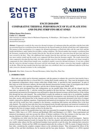
  • 5. 17th Brazilian Congress of Thermal Sciences and Engineering (ENCIT 2018) November 25th-28th, 2018, Águas de Lindóia, SP, Brazil The thermal resistance associated to the total rate of convective heat transfer for the plate fins heat sinks was: Rth,pf = 1 hbi(2LH)ηpf + hL(bL) (19) For the strip fins heat sinks, the heat transfer coefficient hbs was obtained from Eq. (14), where the lower bound and the upper bound fins efficiencies are already included. qt = qf + qL = hbs2(L + S) 1 − S P + hL(bL) (Tw − Ti) (20) Thus, the total thermal resistance for the strip fins heat sinks, including the heat transfer from its base, may be expressed by: Rth,sf = 1 hbs2(L + S) 1 − S P + hL(bL) (21) Comparative results will be presented next for the two heat sink configurations (plate fins and strip fins), using the models presented by Teertstra et al. (1999) and Teertstra et al. (2000), where just the heat transfer from the fins is evaluated, and also the modified model, taking into account the convection from the heat sinks base. 3. RESULTS AND DISCUSSION Numerical tests were performed for heat sinks with the same geometry and material as that tested by Teertstra et al. (1999), in order to compare the present results with their experimental data for strip fins. Their heat sink had a length L = 115mm, fins spacing b = 5, 7mm, height H = 49mm, and thickness t = 1, 25mm. The heat sink thermal conductivity was k = 200 W/m.K and the number of rows of fins was N = 7. For the strip fins, a fixed ratio (S/P) = 0.5 was used in their experiments and in the present simulations, and the predictions were made with two distinct numbers of inline strips (NS) in each fin row: NS = 5 and NS = 10. The numerical tests were performed for an average velocity in the interfins channels (U) in the range from 1 to 10 m/s, associated to the plate fins modified Reynolds number Reb within the limits of validation of the correlations for the Nusselt number (40 < Reb < 180). The results for the average Nusselt number Nub at the fins for both heat sink configurations are presented in Fig. 2 as functions of the modified Reynolds number Reb. For the plate fins heat sink, Nub represents the product of Nubi and ηpf , obtained respectively from Eqs. (6) and (7) and only the prediction results are presented, since there are no experimental data for this configuration. For the strip fins heat sinks, Nub represents the values obtained from Eq. (14). All the numerical results show an increase of Nub with the Reynolds number Reb, but for the plate fins the average Nusselt number is below the values obtained for the strip fins, as expected, according to the mentioned works of Sparrow et al. (1977) and Webb (2007). For the strip fins, the predicted Nusselt number also increases with the Reynolds number Reb and with the number of strips (NS = 5 and 10) in each fin row, due to the corresponding shorter strip lengths and the associated reduction of the thermal boundary layer growth in each strip. The experimental results presented by Teertstra et al. (1999) for the same numbers of strips are also included in this figure to give a comparison to the results of numerical simulations. It should be kept in mind that for the strip fins, the numerical predictions for the Nusselt number are the average of the upper and lower bounds, indicated by Eq. (14). Fig. 2 shows that most of the experimental results were above the predictions for both numbers of strips (NS = 5 and 10) but the relative deviations were within 12%. The heat sinks convective thermal resistances were obtained from Eqs. (8) and (15) respectively for the plate fins and the strip fins when the heat transfer was evaluated only from the fins surfaces. When the heat transfer from the base of the interfins channels was added, the plate fins thermal resistance was obtained from Eq. (19) and for the strip fins heat sinks it was obtained from Eq. (21). The results presented in Fig. 3 include both models for the plate fins and the strip fins heat sinks, showing that all thermal resistances decrease as the interfins flow average velocity increases. They also show that the strip fins have smaller thermal resistances than the plate fins, indicating that the strip fins higher heat transfer coefficients observed in Fig. 2 have a larger effect than their decrease of the heat transfer area, so that their thermal resistance decreases. The results follow the trend observed in Fig. 2 of an increase of the heat transfer coefficient with the number of strips (NS), thus imposing smaller heat sink thermal resistance as NS increases. Comparing the results from both models, it is observed that the inclusion of the heat transfer from the interfins base channel always decreases the heat sinks thermal resistance.
  • 6. William Denner Pires Fonseca and Carlos A. C. Altemani Comparative Thermal Performance of Flat Plate Fins and Inline Strip Fins Heat Sinks 50 100 150 200 4 6 8 10 12 14 16 18 Nub Reb Prediction, Ns = 10 Experimental, Ns = 10 Prediction, Ns = 5 Experimental, Ns = 5 Plate fin Figure 2: Average Nusselt number for the flat plate and the inline strip fins. 0 2 4 6 8 10 0 1 2 3 4 5 6 7 R th [°C/W] U [m/s] Plate fin Plate fin and base Strip fin, Ns = 5 Strip fin and base, Ns = 5 Strip fin, Ns = 10 Srip fin and base, Ns = 10 Figure 3: Effect of the interfin flow average velocity on the heat sinks thermal resistance. 4. CONCLUSIONS The thermal performance of a flat plate heat sink was initially compared to a similar strip fin heat sink by means of correlations for the fins heat transfer obtained from the literature, considering a range of the average flow velocity in the interfins channels. The results indicated that the convective heat transfer coefficients for both heat sinks increase with the interfins channels flow Reynolds number. The convection coefficients were smaller for the plate fins than for the strip fins, as expected from the analyses of Sparrow et al. (1977) and Webb (2007). The results also indicated smaller thermal resistances for the strip fins heat sink, indicating that their larger heat transfer coefficient had a more pronounced effect than the reduction of their heat transfer area, when compared to the plate fins of a similar heat sink. The inclusion of the convective heat transfer from the base of the interfins channels in the previous model indicated a decrease of both heat sinks thermal resistance, with the same trends. Thus, strip fins heat sinks have a better thermal performance than a similar plate fins heat sink under similar operating conditions. To have a broader picture for a heat sink selection, these results should however be compared with the power needed to pump the flow through the heat sink and the final selection should also be based on the design goals for a heat sink.
  • 7. 17th Brazilian Congress of Thermal Sciences and Engineering (ENCIT 2018) November 25th-28th, 2018, Águas de Lindóia, SP, Brazil 5. ACKNOWLEDGEMENTS The support of FAPEMA, the Foundation of Research and Scientific Development of Maranhão, in the form of a Scholarship to the first author, is deeply appreciated. 6. REFERENCES Al-Sallami, W., Al-Damook, A. and Thompson, H., 2016. “A numerical investigation of thermal airflows over strip fin heat sinks”. International Communications in Heat and Mass Transfer, Vol. 75, pp. 183–191. Churchill, S. and Usagi, R., 1972. “A general expression for the correlation of rates of transfer and other phenomena”. AIChE Journal, Vol. 18, No. 6, pp. 1121–1128. Henríquez, J., Bueno, C. and Primo, A., 2007. “Estudo numerico sobre a dissipação térmica num micro-processador comercial”. CEP, Vol. 50740, p. 530. Hong, F. and Cheng, P., 2009. “Three dimensional numerical analyses and optimization of offset strip-fin microchannel heat sinks”. International Communications in Heat and Mass Transfer, Vol. 36, No. 7, pp. 651–656. Jonsson, H. and Moshfegh, B., 2001. “Modeling of the thermal and hydraulic performance of plate fin, strip fin, and pin fin heat sinks-influence of flow bypass”. IEEE Transactions on Components and Packaging Technologies, Vol. 24, No. 2, pp. 142–149. Kadle, D. and Sparrow, E., 1986. “Numerical and experimental study of turbulent heat transfer and fluid flow in longitu- dinal fin arrays”. Journal of heat transfer, Vol. 108, No. 1, pp. 16–23. Ozturk, E. and Tari, I., 2008. “Forced air cooling of cpus with heat sinks: A numerical study”. IEEE transactions on components and packaging technologies, Vol. 31, No. 3, pp. 650–660. Sata, Y., Iwasaki, H. and Ishizuka, M., 1997. “Development of prediction technique for cooling performance of finned heat sink in uniform flow”. IEEE Transactions on Components, Packaging, and Manufacturing Technology: Part A, Vol. 20, No. 2, pp. 160–166. Sparrow, E., Baliga, B. and Patankar, S., 1977. “Heat transfer and fluid flow analysis of interrupted-wall channels, with application to heat exchangers”. Journal of Heat Transfer, Vol. 99, No. 1, pp. 4–11. Sparrow, E., Baliga, B. and Patankar, S., 1978. “Forced convection heat transfer from a shrouded fin array with and without tip clearance”. Journal of Heat Transfer, Vol. 100, No. 4, pp. 572–579. Teertstra, P., Culham, J. and Yovanovich, M., 1999. “Analytical modeling of forced convection in slotted plate fin heat sinks”. ASME-PUBLICATIONS-HTD, Vol. 364, pp. 3–12. Teertstra, P., Yovanovich, M. and Culham, J., 2000. “Analytical forced convection modeling of plate fin heat sinks”. Journal of Electronics Manufacturing, Vol. 10, No. 04, pp. 253–261. Webb, R.L., 2007. “Heat exchanger design methodology for electronic heat sinks”. Journal of heat transfer, Vol. 129, No. 7, pp. 899–901. 7. RESPONSIBILITY NOTICE The authors are the only responsible for the printed material included in this paper.