
Recommended
More Related Content
Similar to Basic electronics175
Similar to Basic electronics175 (20)
More from Viju Jigajinni
Recently uploaded
Recently uploaded (20)
Basic electronics175
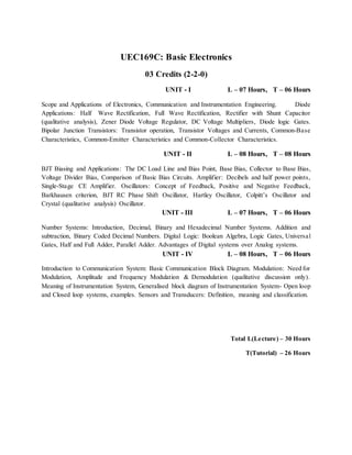
- 1. UEC169C: Basic Electronics 03 Credits (2-2-0) UNIT - I L – 07 Hours, T – 06 Hours Scope and Applications of Electronics, Communication and Instrumentation Engineering. Diode Applications: Half Wave Rectification, Full Wave Rectification, Rectifier with Shunt Capacitor (qualitative analysis), Zener Diode Voltage Regulator, DC Voltage Multipliers, Diode logic Gates. Bipolar Junction Transistors: Transistor operation, Transistor Voltages and Currents, Common-Base Characteristics, Common-Emitter Characteristics and Common-Collector Characteristics. UNIT - II L – 08 Hours, T – 08 Hours BJT Biasing and Applications: The DC Load Line and Bias Point, Base Bias, Collector to Base Bias, Voltage Divider Bias, Comparison of Basic Bias Circuits. Amplifier: Decibels and half power points, Single-Stage CE Amplifier. Oscillators: Concept of Feedback, Positive and Negative Feedback, Barkhausen criterion, BJT RC Phase Shift Oscillator, Hartley Oscillator, Colpitt’s Oscillator and Crystal (qualitative analysis) Oscillator. UNIT - III L – 07 Hours, T – 06 Hours Number Systems: Introduction, Decimal, Binary and Hexadecimal Number Systems. Addition and subtraction, Binary Coded Decimal Numbers. Digital Logic: Boolean Algebra, Logic Gates, Universal Gates, Half and Full Adder, Parallel Adder. Advantages of Digital systems over Analog systems. UNIT - IV L – 08 Hours, T – 06 Hours Introduction to Communication System: Basic Communication Block Diagram. Modulation: Need for Modulation, Amplitude and Frequency Modulation & Demodulation (qualitative discussion only). Meaning of Instrumentation System, Generalised block diagram of Instrumentation System- Open loop and Closed loop systems, examples. Sensors and Transducers: Definition, meaning and classification. Total L(Lecture) – 30 Hours T(Tutorial) – 26 Hours
- 2. TextBooks : 1. David A. Bell, “Electronic Devices and Circuits”, 4th edition, PHI, 2006. 2. George Kennedy, “Electronic Communication Systems”, 4th edition. TMH, 2005. Reference Books : 1. Floyd and Jan, “Digital fundamentals”, 8th edition, Pearson, 2006. 2. Jacob Milliman, Christos C. Halkies, “Electronics Devices and Circuits”, TMH, 2001. 3. A.P. Malvino, “Electronic Principles”, TMH, 2003. Course Outcomes A student who successfully completes this course should be able to 1. Analyze and design diode circuits, configure transistor circuits. 2. Distinguish transistor biasing methods and design oscillators. 3. Do number system conversions, and implement basic logic circuits. 4. Comprehend the necessity of communication systems and need for modulation.