
Recommended
More Related Content
What's hot
Viewers also liked
Viewers also liked (19)
Similar to SummitCatalog
Similar to SummitCatalog (20)
SummitCatalog
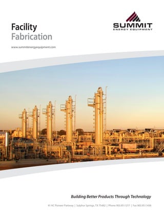
- 1. Facility Fabrication www.summitenergyequipment.com Building Better Products Through Technology 41 HC Pioneer Parkway | Sulphur Springs, TX 75482 | Phone 903.951.1217 | Fax 903.951.1436 SUMMITE N E R G Y E Q U I P M E N T SUMMITE N E R G Y E Q U I P M E N T
- 2. Facility Fabrication Many energy companies are now implementing fully- sustained facilities to manage multiple well sites in many oil field plays. These pre-engineered stations require a manufacturing facility that has incredible attention to detail, material traceability and shop control. Summit Energy Equipment is proud to offer this service to any company looking to follow this type of methodology. Please contact our sales staff to submit isometric drawings and Bid Packages. Summit Energy Equipment offers off-site piping and vessel fabrication for Gathering Facilities and Compressor Stations. In our current facility, we are able to produce tens of thousands of weld IN/day of finished product in the effort to drastically diminish lead times and provide an opportunity to increase your productivity and margins with a very cost-effective solution. We currently fabricate ICP, Main Rack Piping and Pipe Support for Gathering Facilities in South and West Texas. Our products endure a rigorous inspection and checkout procedure that will insure that your products arrive on-site with no repairs and time lost. Our products come complete with as-built drawings, traceability maps and MTR on all material used in fabrication. Data books are available online through our ASSET INFORMATION CENTER (AIC) as well as a hard copy shipped to any location that is requested. Our Vessel Fabrication Division is very well equipped with design and development software to aid Facility Fabrication in the fast-paced environment of facility manufacturing. Our Engineering staff is equipped with the latest Design Software and is equipped to handle most 3D CAD file types. This allows easy integration of customer expectations and review of design concepts before and during fabrication. We are a rapidly evolving manufacturing company with a desire to provide the most impressive and convenient customer experience possible. Our facility can currently handle vessels up to 96” in diameter and as long as 40’ S/S. Incorporating the same procedures as the pipe fabrication, our facility is an ASME coded facility that will be obtaining an ISO 9001:2008 Compliance very soon. These certifications are the basis for our Quality Policy and Procedures that allow our customers to gain confidence in our capabilities as a manufacturer. Building Better Products Through Technology Building Better Products Through Technology 41 HC Pioneer Parkway | Sulphur Springs, TX 75482 | Phone 903.951.1217 | Fax 903.951.1436 41 HC Pioneer Parkway | Sulphur Springs, TX 75482 | Phone 903.951.1217 | Fax 903.951.1436 SUMMITE N E R G Y E Q U I P M E N T SUMMITE N E R G Y E Q U I P M E N T SUMMITE N E R G Y E Q U I P M E N T SUMMITE N E R G Y E Q U I P M E N T
- 3. Facility Specifications FABRICATION SPECIFICATIONS FlareTube Length 25’- 78’ FlareTube Diameter 4”- 10” Trailer Capacity 2 - 7000# axles Outriggers 20 feet w/ Stabilizing Struts Liquid Collector 18”x 8’S/S 75 PSI KOD (ASME code optional) Electrical 12VDC Hydraulic 30”stroke (2500 PSI UP/500 PSI DOWN) Ignitors DBI/ACL Service Sweet/Sour Gas Crew Size 2-Person SEPARATORS MAWP 15 - 5800 PSI MDMT -50 - 250 F Construction Code ASME SectionVIII Division I Stamps Available U, R, NB Mounting Trailer - Skid-Mounted I/O 2”- 6”FullyWelded/Threaded PSV Single or Redundant Dimensions 8”- 96” Service Sweet/Sour Gas Mist Extractor Vane - MeshType Building Better Products Through Technology Building Better Products Through Technology 41 HC Pioneer Parkway | Sulphur Springs, TX 75482 | Phone 903.951.1217 | Fax 903.951.1436 41 HC Pioneer Parkway | Sulphur Springs, TX 75482 | Phone 903.951.1217 | Fax 903.951.1436 SUMMITE N E R G Y E Q U I P M E N T SUMMITE N E R G Y E Q U I P M E N T SUMMITE N E R G Y E Q U I P M E N T SUMMITE N E R G Y E Q U I P M E N T
- 4. Three Phase Separator www.summitenergyequipment.com Three Phase Separator Summit’s three phase separator is used to separate oil, gas and water so that accurate measurement can be made on each phase. Various size meter runs are offered which measure gas flow. Turbine meters are supplied to measure the liquid ow rates both in produced water and oil outlet piping. These separators come in a variety of sizes. Summit‘s capabilities include diameters from 8” to 96” and lengths up to 20’ long. Pressures range from 50 psi to 2000 psi. The separators can be supplied with dual pressure relief valves. Based on piping design, these separators have sufficient valving to by-pass critical components or combine outlet flows as needed. These can be supplied with a complete by-pass on the inlet stream as well in order to go around the separator if needed. Building Better Products Through Technology Building Better Products Through Technology 41 HC Pioneer Parkway | Sulphur Springs, TX 75482 | Phone 903.951.1217 | Fax 903.951.1436 41 HC Pioneer Parkway | Sulphur Springs, TX 75482 | Phone 903.951.1217 | Fax 903.951.1436 SUMMITE N E R G Y E Q U I P M E N T SUMMITE N E R G Y E Q U I P M E N T SUMMITE N E R G Y E Q U I P M E N T SUMMITE N E R G Y E Q U I P M E N T
- 5. Separator Specifications SPECIFICATIONS MAWP 15 - 5800 PSI MDMT -50 - 250 F Construction Code ASME SectionVIII Division I Stamps Available U, R, NB Mounting Trailer - Skid-Mounted I/O 2”- 6”FullyWelded/Threaded PSV Single or Redundant Dimensions 8”- 96” Service Sweet/Sour Gas Mist Extractor Vane - MeshType CONNECTIONS 900# RF - Inlet, Gas Outlet 4” NPT – Oil LLC,Water LLC, Oil Outlet,Water Outlet, Drain, Relief (2) 2” NPT – Oil Gauge Glass (2),Water Gauge Glass (2),T.I. 3/4” NPT – Pressure Indicator, Supply Gas 1/2” Complete with valves and instrumentation including: • 4” Daniel Sr. Meter run, • Scanner 2000 digital flow meter, • Norriseal 1001 Level Controllers, • Taylor relief valves, • Balon hand valves , • Kimray 2150 dump valves, • Fisher pressure regulator Building Better Products Through Technology Building Better Products Through Technology 41 HC Pioneer Parkway | Sulphur Springs, TX 75482 | Phone 903.951.1217 | Fax 903.951.1436 41 HC Pioneer Parkway | Sulphur Springs, TX 75482 | Phone 903.951.1217 | Fax 903.951.1436 SUMMITE N E R G Y E Q U I P M E N T SUMMITE N E R G Y E Q U I P M E N T SUMMITE N E R G Y E Q U I P M E N T SUMMITE N E R G Y E Q U I P M E N T
- 6. Sand Separator www.summitenergyequipment.com Sand Separator Specifications SPECIFICATIONS MAWP 10000 PSI (API), 5800 PSI (ASME) MDMT -50 - 250 F Construction Code ASME SectionVIII Division I - API 6A Stamps Available U, R, NB Mounting Trailer - Skid-Mounted I/O 2”- 6”FullyWelded PSV Spring-operated/Rupture Disk Dimensions 11”to 20”ID Service Sweet/Sour Gas Sand Separators are used to extract produces solids from the wellstream either before or after the choke manifold. In order to separate these solids the mixture enters the sand separator and strikes a sacrificial flow diverter and allows the solids to fall out of the mixture. Our separators can be designed for low pressure or high pressure situations. We offer an ASME and API style with multiple inlet diverter designs to fit the current flow characteristics experienced by the well. Both styles offer over pressure protection by either PSVs or ruptured disk and are mounted to a standard Oilfield L-Skid with trailer mounting solutions. Building Better Products Through Technology Building Better Products Through Technology 41 HC Pioneer Parkway | Sulphur Springs, TX 75482 | Phone 903.951.1217 | Fax 903.951.1436 41 HC Pioneer Parkway | Sulphur Springs, TX 75482 | Phone 903.951.1217 | Fax 903.951.1436 SUMMITE N E R G Y E Q U I P M E N T SUMMITE N E R G Y E Q U I P M E N T SUMMITE N E R G Y E Q U I P M E N T SUMMITE N E R G Y E Q U I P M E N T
- 7. Flare Stack Gas Combustion www.summitenergyequipment.comwww.summitenergyequipment.com To Learn more about our products or Request a Custom Quote Contact Us: Summit Energy Equipment 41 HC Pioneer Parkway Sulphur Springs, TX 75482 Phone 903.951.1217 Fax 903.951.1436 sales@summitenergyequipment.com www.summitenergyequipment.com Building Better Products Through Technology Building Better Products Through Technology 41 HC Pioneer Parkway | Sulphur Springs, TX 75482 | Phone 903.951.1217 | Fax 903.951.1436 41 HC Pioneer Parkway | Sulphur Springs, TX 75482 | Phone 903.951.1217 | Fax 903.951.1436 SUMMITE N E R G Y E Q U I P M E N T SUMMITE N E R G Y E Q U I P M E N T SUMMITE N E R G Y E Q U I P M E N T SUMMITE N E R G Y E Q U I P M E N T
- 8. Flare Stack Advantages Flare Tube Length ........................................................................................................................... 25’ - 78’ Flare Tube Diameter ....................................................................................................................... 4” - 10” Trailer Capacity ................................................................................................................. 2 - 7000lb axles Outriggers ...................................................................................................... 20 feet w/ Stabilizing Struts Liquid Collector .................................................................. 18” x 8’ S/S 75 PSI KOD (ASME code optional) Electrical ......................................................................................................................................... 12 VDC Hydraulic .................................................................................... 30” stroke (2500 PSI UP/500 PSI DOWN) Ignitors ........................................................................................................................................... DBI/ACL Service ............................................................................................................................... Sweet/Sour Gas Crew Size ...................................................................................................................................... 2-Person Flare Stack Specifications 4 x 40 6 x 604 x 60 Flare Stack Advantages ADVANTAGES Summit Flare Stacks are used to burn gas during drilling and completing operations. This allows gas to be burned at a safe distance from the well head. This creates a much safer environment for workers. Our Flare Stacks are also designed and built to MR0175 NACE standard. Flare Stacks are equipped with a gas pilot that is red with a shot-tube type ignition system on our standard equipment. We also offer an electronic igniter that sparks every 2 seconds to ensure minimal gas escaping without being burned. Available in 4” to 10” in diameter and 25’ to 60’ in height. These can be either trailer or skid mounted with guy wires to secure once in the upright operating position. Fully self sufficient, solar charging hydraulic system to lower and raise stack easily by one or two operators. Flares are equipped with a counter-balancing valve that serves two important functions. One is it makes the raising and lowering function very smooth as well as serves to stop the movement should a hydraulic hose ruptures during operations. Flares can also be purchased with an integral liquid collector/knock-out. Offered both as ASME coded or uncoded versions. EPA Requirements Flare Systems Meet All EPA Requirements Summit open flare systems are guaranteed to meet EPA requirements for 40 CFR 60.18 and have destruction removal efficiency (DRE) of 98%. If higher destruction is required, an enclosed flare system may be utilized if it is economically practical. Our designs are based on experience with flare installations and flow medium analysis supplied by customer. Summit is a leader in flare system innovation and design, having supplied and installed successful, proven systems nationwide. From our use of modern structural and control techniques, to our proven flare tip and seal designs, Summit is committed to manufacturing the best flares built. We are able to accomplish this goal in part due to the following: Summit believes in safety first. Our flare system designs adhere to the strictest of safety standards. Flares are of the highest quality. Flare Pilots are designed for years of reliable, continuous operation. Summit Flame Retention Rings promote stable combustion and prevent lift-off at high exit velocities. Summit Purge Seals are designed for maximum efficiency and low operating cost. Prompt and reliable pilot ignition/ monitoring systems allow for optimum performance of the flare systems. Our experience and relentless pursuit to keep our customers happy are unmatched in the combustion and flare industries. Flare Tube Length ........................................................................................................................... 25’ - 78’ Flare Tube Diameter ....................................................................................................................... 4” - 10” Trailer Capacity ................................................................................................................. 2 - 7000lb axles Outriggers ...................................................................................................... 20 feet w/ Stabilizing Struts Liquid Collector .................................................................. 18” x 8’ S/S 75 PSI KOD (ASME code optional) Electrical ......................................................................................................................................... 12 VDC Hydraulic .................................................................................... 30” stroke (2500 PSI UP/500 PSI DOWN) Ignitors ........................................................................................................................................... DBI/ACL Service ............................................................................................................................... Sweet/Sour Gas Crew Size ...................................................................................................................................... 2-Person Flare Stack Specifications 4 x 40 6 x 604 x 60 Building Better Products Through Technology Building Better Products Through Technology 41 HC Pioneer Parkway | Sulphur Springs, TX 75482 | Phone 903.951.1217 | Fax 903.951.1436 41 HC Pioneer Parkway | Sulphur Springs, TX 75482 | Phone 903.951.1217 | Fax 903.951.1436 SUMMITE N E R G Y E Q U I P M E N T SUMMITE N E R G Y E Q U I P M E N T SUMMITE N E R G Y E Q U I P M E N T SUMMITE N E R G Y E Q U I P M E N T
- 9. Summit’s SP8 Series Spark Ignited Pilots are designed to provide an ignition source for small to medium size flares. Ignition of the pilot gas is assured by an intermittent spark in the pilot nozzle every two seconds regardless of the pilot flame temperature. Control for the SP8 Series Pilots includes a Spark Oscillator Module, thermocouple controller (with alarm contacts and an analog temperature retransmission signal), battery and battery charger in a Nema 4 fiberglass enclosure. The standard controls for the SP8 Series Pilots are designed to operate on 120 VAC and will provide 10 hours of operation during power disruption. Minimum methane requirement for this pilot is 70scfh@ 5 psi. As with all of our equipment, custom pilots and controls are offered to meet field requirements. • Burner fabrication material 306 SS • Pilot fabrication material 306 SS • Stack fabrication material A-106 NACE • Wind loading analyses for 80 MPH Flare Stack Pilot Igniter Summit’s SP8 Series Spark Ignited Pilots are designed to provide an ignition source for small to medium size flares. Ignition of the pilot gas is assured by an intermittent spark in the pilot nozzle every two seconds regardless of the pilot flame temperature. Control for the SP8 Series Pilots includes a Spark Oscillator Module, thermocouple controller (with alarm contacts and an analog temperature retransmission signal), battery and battery charger in a Nema 4 fiberglass enclosure. The standard controls for the SP8 Series Pilots are designed to operate on 120 VAC and will provide 10 hours of operation during power disruption. Minimum methane requirement for this pilot is 70scfh@ 5 psi. As with all of our equipment, custom pilots and controls are offered to meet field requirements. • Burner fabrication material 306 SS • Pilot fabrication material 306 SS • Stack fabrication material A-106 NACE • Wind loading analyses for 80 MPH Flare Stack Pilot Igniter Warranty applies to fabrication, defective workmanship or materials, assembly and manufactured components. Summit Energy Equipment warrants all fabrication and assembly for one (1) year from the date that each flare is commissioned successfully. Warranty does not cover the removal, re-installation or modification of equipment. All manufacturers’ warranties for third party components installed are passed on and these items are not underwritten by Summit Energy Equipment. Any defective component must be returned to Summit for replacement under warranty. Shipping costs and labor to replace the items are not covered by warranty. Summit Energy Equipment guarantees and warrants that the environmental control equipment supplied will effectively thermally oxidize the waste gas for the process conditions specified herein. Summit Energy Equipment does not provided any performance guarantee if the operating conditions differ from the client specified design conditions as detailed in this proposal or if the sizing and design of the equipment has been provided to Summit by others. Summit Energy Equipment liability hereunder shall be limited to the obligation to repair or replace only those products proven to have been defective in material or workmanship at the time of delivery. Warranty does not cover the removal, re-installation or modification of equipment. Summit Energy Equipment total cumulative liability in any way arising from or pertaining to any product sold or required to be sold under this contract shall not in any case exceed the purchase price paid by Buyer for such products. In no event shall Summit Energy Equipment have any liability for commercial loss, lost profits, claims for labor, or consequential or incidental damages of any type, whether buyer’s claim be based in contract, tort, warranty, strict liability, negligence, or otherwise. It is expressly agreed that buyer’s remedies expressed herein are buyer’s sole and exclusive remedies. The above stated warranty, which is given expressly in lieu of all other warranties, expressed or implied by the customer, trade usage or law, including warranties of merchantability and fitness for particular purpose, constitutes the only warranty made by the seller. Flare Stack Warranty Building Better Products Through Technology Building Better Products Through Technology 41 HC Pioneer Parkway | Sulphur Springs, TX 75482 | Phone 903.951.1217 | Fax 903.951.1436 41 HC Pioneer Parkway | Sulphur Springs, TX 75482 | Phone 903.951.1217 | Fax 903.951.1436 SUMMITE N E R G Y E Q U I P M E N T SUMMITE N E R G Y E Q U I P M E N T SUMMITE N E R G Y E Q U I P M E N T SUMMITE N E R G Y E Q U I P M E N T
- 10. Flare Stack Smokeless Burner www.summitenergyequipment.com Flare Stack Smokeless Burner To Learn more about our products or Request a Custom Quote Contact Us: Summit Energy Equipment 41 HC Pioneer Parkway Sulphur Springs, TX 75482 Phone 903.951.1217 Fax 903.951.1436 sales@summitenergyequipment.com www.summitenergyequipment.com Building Better Products Through Technology Building Better Products Through Technology 41 HC Pioneer Parkway | Sulphur Springs, TX 75482 | Phone 903.951.1217 | Fax 903.951.1436 41 HC Pioneer Parkway | Sulphur Springs, TX 75482 | Phone 903.951.1217 | Fax 903.951.1436 SUMMITE N E R G Y E Q U I P M E N T SUMMITE N E R G Y E Q U I P M E N T SUMMITE N E R G Y E Q U I P M E N T SUMMITE N E R G Y E Q U I P M E N T
- 11. Flare Stack Smokeless Burner Advantages Summit offers Flare-Tip Burners capable of combustion completion when operated within design parameters set forth by Summit. Summit Smokeless Flare Burners include necessary internal components for efficiency, stability, and will meet or exceed current regulation requirements. Design parameters have been developed by Summit in order to operate the Smokeless Flare Burners. The burners have been designed with calculations for sizing two stages of air to mix with the waste gas to complete combustion. Summit has designed eight of these unique combustion burners for eight different site ranges. Summit can custom design burners for specific site conditions as needed. Summit has designed several variable smokeless flare burner tips using Jerry Lang’s Patented Technology, ranging from 1MSCFD to 6MMSCFD. These tips are available on new stationary and mobile flare stacks. Our flares are truly smokeless based on your site conditions including flow rates, waste gas composition, and pressure available. We design each burner to mix proper air with the gas coming off of your facility without blowers or steam. While you can buy similar systems from others, Emission control is our advantage and what we have been doing for many years. EPA Requirements Flare Systems Meet All EPA Requirements Summit open flare systems are guaranteed to meet EPA requirements for 40 CFR 60.18 and have destruction removal efficiency (DRE) of 98%. If higher destruction is required, an enclosed flare system may be utilized if it is economically practical. Our designs are based on experience with flare installations and flow medium analysis supplied by customer. Summit is a leader in flare system innovation and design, having supplied and installed successful, proven systems nationwide. From our use of modern structural and control techniques, to our proven flare tip and seal designs, Summit is committed to manufacturing the best flares built. We are able to accomplish this goal in part due to the following: Summit believes in safety first. Our flare system designs adhere to the strictest of safety standards. Flares are of the highest quality. Flare Pilots are designed for years of reliable, continuous operation. Summit Flame Retention Rings promote stable combustion and prevent lift-off at high exit velocities. Summit Purge Seals are designed for maximum efficiency and low operating cost. Prompt and reliable pilot ignition/monitoring systems allow for optimum performance of the flare systems. Our experience and relentless pursuit to keep our customers happy are unmatched in the combustion and flare industries. Flare Stack Smokeless Tip Specifications Tip Specifications 1. GAS & SITE ANALYSIS TO COMPLY WITH • MSCF/d - Minimum/Maximum • PSI - Minimum Available/Maximum Available • BTU/ft3 / Specific Gravity 2. OTHER CONSIDERATIONS • Tip Velocity is calculated at less than 400 ft/sec • Ideal pressure on standard Summit burners is 30 PSI except when higher BTU gas is being burned than what the tip is designed for • Explanation: Heavier gasses (2,300 BTU/ft3 would use lower pressure than what the tip is for if it is designed for (1,400 BTU/ft3) 3. BURNER TIP CAPACITY FLOW RATE • 0 - 1,000,000 MSCF/d • 1,000,000 - 2,000,000 MSCF/d • 2,000,000 - 4,000,000 MSCF/d • 4,000,000 - 6,000,000 MSCF/d Guarantee Summit can guarantee that when the smokeless burners are operated within their designed parameters, they will burn smokeless. H2S FLARING Hydrogen sulfide is a toxic gas and is most commonly obtained by its separation from sour gas, which is natural gas with high content of H2S. In most cases, this gas must be flared for the protection of people as well as environment. Many flares around shale areas are only flaring 40-50% of the hydrocarbons, leaving unburned hydrocarbons going into the atmosphere. H2S is slightly heavier than air so typical flares are not safe for combusting this molecular weight of gas while Summit’s flare burners combust this gas and burn it off first. Uses • Gas Well Facilities • Flowback & H2S Flaring • Centrifugal and Reciprocating Compressor Facilities • Pneumatic Controller Facilities • Storage Vessels & Tank Battery Facilities • Equipment Leaks Facilities • Sweetening Unit Facilities • Natural Gas Processing Plants • Crude Oil Tanker Vents and L.A.C.T. Building Better Products Through Technology Building Better Products Through Technology 41 HC Pioneer Parkway | Sulphur Springs, TX 75482 | Phone 903.951.1217 | Fax 903.951.1436 41 HC Pioneer Parkway | Sulphur Springs, TX 75482 | Phone 903.951.1217 | Fax 903.951.1436 SUMMITE N E R G Y E Q U I P M E N T SUMMITE N E R G Y E Q U I P M E N T SUMMITE N E R G Y E Q U I P M E N T SUMMITE N E R G Y E Q U I P M E N T
- 12. 4 x 40 6 x 604 x 60 Flare Tube Length ........................................................................................................................... 25’ - 78’ Flare Tube Diameter ....................................................................................................................... 4” - 10” Trailer Capacity ................................................................................................................. 2 - 8000lb axles Outriggers ...................................................................................................... 20 feet w/ Stabilizing Struts Liquid Collector .................................................................. 18” x 8’ S/S 75 PSI KOD (ASME code optional) Electrical ......................................................................................................................................... 12 VDC Hydraulic .................................................................................... 30” stroke (2500 PSI UP/500 PSI DOWN) Ignitors ........................................................................................................................................... DBI/ACL Service ............................................................................................................................... Sweet/Sour Gas Crew Size ...................................................................................................................................... 2-Person Flare Stack Specifications Warranty applies to fabrication, defective workmanship or materials, assembly and manufactured components. Summit Energy Equipment warrants all fabrication and assembly for one (1) year from the date that each flare is commissioned successfully. Warranty does not cover the removal, re-installation or modification of equipment. All manufacturers’ warranties for third party components installed are passed on and these items are not underwritten by Summit Energy Equipment. Any defective component must be returned to Summit for replacement under warranty. Shipping costs and labor to replace the items are not covered by warranty. Summit Energy Equipment guarantees and warrants that the environmental control equipment supplied will effectively thermally oxidize the waste gas for the process conditions specified herein. Summit Energy Equipment does not provided any performance guarantee if the operating conditions differ from the client specified design conditions as detailed in this proposal or if the sizing and design of the equipment has been provided to Summit by others. Summit Energy Equipment liability hereunder shall be limited to the obligation to repair or replace only those products proven to have been defective in material or workmanship at the time of delivery. Warranty does not cover the removal, re-installation or modification of equipment. Summit Energy Equipment total cumulative liability in any way arising from or pertaining to any product sold or required to be sold under this contract shall not in any case exceed the purchase price paid by Buyer for such products. In no event shall Summit Energy Equipment have any liability for commercial loss, lost profits, claims for labor, or consequential or incidental damages of any type, whether buyer’s claim be based in contract, tort, warranty, strict liability, negligence, or otherwise. It is expressly agreed that buyer’s remedies expressed herein are buyer’s sole and exclusive remedies. The above stated warranty, which is given expressly in lieu of all other warranties, expressed or implied by the customer, trade usage or law, including warranties of merchantability and fitness for particular purpose, constitutes the only warranty made by the seller. Flare Stack Warranty Building Better Products Through Technology Building Better Products Through Technology 41 HC Pioneer Parkway | Sulphur Springs, TX 75482 | Phone 903.951.1217 | Fax 903.951.1436 41 HC Pioneer Parkway | Sulphur Springs, TX 75482 | Phone 903.951.1217 | Fax 903.951.1436 SUMMITE N E R G Y E Q U I P M E N T SUMMITE N E R G Y E Q U I P M E N T SUMMITE N E R G Y E Q U I P M E N T SUMMITE N E R G Y E Q U I P M E N T
- 13. To Learn more about our products or Request a Custom Quote Contact Us: Summit Energy Equipment 41 HC Pioneer Parkway Sulphur Springs, TX 75482 Phone 903.951.1217 Fax 903.951.1436 sales@summitenergyequipment.com www.summitenergyequipment.com Plug Catcher www.summitenergyequipment.com Building Better Products Through Technology Building Better Products Through Technology 41 HC Pioneer Parkway | Sulphur Springs, TX 75482 | Phone 903.951.1217 | Fax 903.951.1436 41 HC Pioneer Parkway | Sulphur Springs, TX 75482 | Phone 903.951.1217 | Fax 903.951.1436 SUMMITE N E R G Y E Q U I P M E N T SUMMITE N E R G Y E Q U I P M E N T SUMMITE N E R G Y E Q U I P M E N T SUMMITE N E R G Y E Q U I P M E N T
- 14. Plug Catcher Specifications SPECIFICATIONS Valve Configuration 5 - 7 - 9 valve Inlet 3”1502 Female Outlet 2”1502 Male Screen Size and Area 2”Screen w/ 1”slots Barrel Size 6”SCH XXS x 4’S/S Bypass Size 2”SCH XXS Gauge Connections 9/16”AUTOCLAVE Upstream/Downstream Capacity - Service Sweet/Sour Gas CWP 10000 PSI (NACE)/ 15000 PSI (Sweet) Summit’s Plug Catcher is designed to recover large solid pieces of debris that follows the fracking process. This piece of equipment is usually placed just downstream of the well head and just upstream of the choke manifold so it is the first piece of equipment that the well effluent is passed through. The screens have .250 x 1.000 slots positioned throughout the stinger (filter). Well effluent is passed through the screens and the solids larger than the slots are stopped and can be flushed later once the screen is plugged. Our dual design allows the flow to be redirected to the other side thus preventing any interruption during the flowback process. Should both screens become clogged, a 2” by-pass line runs down the middle of the catcher if needed. This piece of equipment is vital in prolonging downstream equipment such as choke manifolds, line heaters, sand separators, and test separators. Plug Catcher Configuration Item Description Quantity 1 Skid 1 2 PlugValve, 3 in x 1502 4 3 Cross, 3 in 1502 MMMF 1 4 Tee, 3 in x 1502 MMF 2 5 Tee, Custom 2 in x 1502 MFM 2 6 PlugValve, 2in 1502 FM 6 7 Cross, 2 in x 1502 FFFM 1 8 Flow Line Pup, 3 in -2 in X 1502 1 9 6 in Plug Catcher Shell 2 10 Stinger 2 11 U-Bolt, 6" Pipe 4 12 U-Bolt, 2 in pipe 1 1 4 2 3 8 6 5 7 9 10 Building Better Products Through Technology Building Better Products Through Technology 41 HC Pioneer Parkway | Sulphur Springs, TX 75482 | Phone 903.951.1217 | Fax 903.951.1436 41 HC Pioneer Parkway | Sulphur Springs, TX 75482 | Phone 903.951.1217 | Fax 903.951.1436 SUMMITE N E R G Y E Q U I P M E N T SUMMITE N E R G Y E Q U I P M E N T SUMMITE N E R G Y E Q U I P M E N T SUMMITE N E R G Y E Q U I P M E N T
- 15. Choke Manifold www.summitenergyequipment.com Manifold Specifications SPECIFICATIONS Valve Conguration 5 - valve Inlet 2”1502 Female Outlet 2”1502 Male Choke Conguration Positive or Adjustable Seals Viton Bypass Size 2”SCH XXS Gauge Connections 9/16”AUTOCLAVE Downstream Capacity - Service Sweet/Sour Gas CWP 10000 PSI (NACE)/ 15000 PSI (Sweet) Summit’s Choke Manifold is used to control pressure from the wellhead and maintain flow through a controlled orifice or choke bean. The manifold comes with either two adjustable or two positive chokes. These Manifolds can be supplied with spare parts such as choke stems and seats for the adjustable chokes. Building Better Products Through Technology Building Better Products Through Technology 41 HC Pioneer Parkway | Sulphur Springs, TX 75482 | Phone 903.951.1217 | Fax 903.951.1436 41 HC Pioneer Parkway | Sulphur Springs, TX 75482 | Phone 903.951.1217 | Fax 903.951.1436 SUMMITE N E R G Y E Q U I P M E N T SUMMITE N E R G Y E Q U I P M E N T SUMMITE N E R G Y E Q U I P M E N T SUMMITE N E R G Y E Q U I P M E N T
- 16. Flow Line www.summitenergyequipment.com Flow Line Specifications SPECIFICATIONS MAWP 2000 - 15000 PSI MDMT -50 - 250 F Construction Code ASME B31.3 Connections Fig. 206 - 1502 Hammer Unions Seals Viton NDE RT and 1.5 Hydro Banding 316SS DataTag Capacity - Service Sweet/Sour Gas Material Normalized Carbn Steel Flow Line is used to connect well-testing equipment in the Flowback Process. Based on the various needs of individual yards, Flow Line can be designed specifically for the needs of the MAWP. Summit manufactures flowline in a variety of sizes with 2” to 3” - 1502, 2” to 3”-602, and 2”to 3”-206 being the most common along with a MAWP of 2000 to 15000 psi. Building Better Products Through Technology Building Better Products Through Technology 41 HC Pioneer Parkway | Sulphur Springs, TX 75482 | Phone 903.951.1217 | Fax 903.951.1436 41 HC Pioneer Parkway | Sulphur Springs, TX 75482 | Phone 903.951.1217 | Fax 903.951.1436 SUMMITE N E R G Y E Q U I P M E N T SUMMITE N E R G Y E Q U I P M E N T SUMMITE N E R G Y E Q U I P M E N T SUMMITE N E R G Y E Q U I P M E N T
- 17. Gas Scrubber www.summitenergyequipment.com Gas Scrubber Specifications Summit’s gas scrubbers are typically used on a multi-well pad sites to supply dry gas for instrumentation and valving. Typicall sizes are 8” to 12” in diameter and 5 to 8 feet tall. Specifications • Built and U-Stamped to ASME Section VIII Div. 1 • National Board Registration is available • 285 PSI CWP • 2”/3” Inlet and Outlet • Redundant Big Joe Regulators on Inlet/Outlet • PSV mounted on vessel and downstream of each regulator • Methanol Injection Valves • Liquid level control w/ siphon drain • Skid-mounted • Certified for NACE MR01-75 • Full Material Traceability and Lot Tracking on each material • Painted per Customer Specifications Building Better Products Through Technology Building Better Products Through Technology 41 HC Pioneer Parkway | Sulphur Springs, TX 75482 | Phone 903.951.1217 | Fax 903.951.1436 41 HC Pioneer Parkway | Sulphur Springs, TX 75482 | Phone 903.951.1217 | Fax 903.951.1436 SUMMITE N E R G Y E Q U I P M E N T SUMMITE N E R G Y E Q U I P M E N T SUMMITE N E R G Y E Q U I P M E N T SUMMITE N E R G Y E Q U I P M E N T
- 18. Contact Request a Quote To Learn more about our products or Request a Custom Quote Contact Us: Summit Energy Equipment 41 HC Pioneer Parkway Sulphur Springs, TX 75482 Phone 903.951.1217 Fax 903.951.1436 sales@summitenergyequipment.com www.summitenergyequipment.com Building Better Products Through Technology Building Better Products Through Technology 41 HC Pioneer Parkway | Sulphur Springs, TX 75482 | Phone 903.951.1217 | Fax 903.951.1436 41 HC Pioneer Parkway | Sulphur Springs, TX 75482 | Phone 903.951.1217 | Fax 903.951.1436 SUMMITE N E R G Y E Q U I P M E N T SUMMITE N E R G Y E Q U I P M E N T SUMMITE N E R G Y E Q U I P M E N T SUMMITE N E R G Y E Q U I P M E N T
- 19. SUMMITE N E R G Y E Q U I P M E N T Summit Energy Equipment 41 HC Pioneer Parkway Sulphur Springs, TX 75482 Phone 903.951.1217 Fax 903.951.1436 sales@summitenergyequipment.com www.summitenergyequipment.com