SlideShare a Scribd company logo
1 of 32
Download to read offline
(281) 482-4728 • www.scvvalve.com
Thru Conduit Slab & Expanding GateValves
Class: 150 - 1500
Sizes: 2”- 36”
SOUTHERN CALIFORNIAVALVE manufactures some of the most
dependable cast steelThru Conduit Slab and Expanding GateValves in the
industry. Both designs utilize flanged and butt-weld end connections, and
are manufactured and tested in accordance with API 6D. The full port
design minimizes pressure drop and turbulence. The SCV design offers
many features and options beneficial for oil, gas, and liquid applications
making it the most demandedThru Conduit Gate on the market.
Innovative valve solutions.®
SCVThru Conduit Slab & Expanding GateValves
								 [ Product Preview ]
SCVTHRU CONDUIT SLAB GATE (BI-DIRECTIONAL)
	 Pressure assisted seats for high pressure sealing
	 Spring loaded seat for low pressure sealing
	 Double block and bleed capabilities
	 Internal pressure relieving through self relieving seats
	 Secondary sealant injection at seats and stems
	 Full port thru conduit for passage of pigs
SCVTHRU CONDUIT EXPANDING GATE
(BI-DIRECTIONAL)WITH PREFERRED PRESSURE SIDE
	 Expanding mechanical gate forms positive tight sealing
	 Seals at low and high pressure
	 Double block and bleed capabilities
	 Secondary sealant injections at seats and stems
	 Optional by-pass system for thermal cavity relief venting
	 Full port thru conduit for passage of pigs
BASIC DESIGN
API 6D
FIRE SAFE DESIGN
API 6FA
FACETO FACE DIMENSION
ANSI B16.10
FLANGE END DIMENSION
ANSI B16.5 (2”to 24”)
ANSI B16.47 & MSS SP-44 (26”& up)
BUTT-WELD END DIMENSION
ANSI B16.25
INSPECTION &TESTING
API 6D
Note: Not recommended for throttling applications.
Note: SCV reserves the right to change any technical design and
dimensional data without prior notice. Please contact SCV to
confirm all Dimensions and Data offered in this catalog.
For more information call us @ (281) 482-4728 or visit our website @ www.scvvalve.com
Southern California Valve’s product lines include commodity valves as well as specialty valves in all Sizes, Pressure Classes &
Metallurgy; including Carbon Steel, Stainless Steel & Exotic Alloys. The valve types include Gate, Globe, Swing Check - Bolted
Bonnet & Pressure Seal Bonnet, Ball - floating, trunnion, rising stem, Thru-Conduit Gate - slab and expanding, Swing Check - Full
and Regular Port, Lubricated Plugs, Dual Plate Checks - wafer and lug. Southern California Valve’s High Quality Standards demand
100% pressure testing of every valve to insure its reliability and full customer satisfaction.
At Southern California Valve, we pride ourselves with high quality products in the commodity and specialty valve lines, as well as,
timely deliveries, and competitive prices.
Company History
Southern California Valve was established in 1972. The primary focus of the Company was to provide full inline field service for
valve maintenance as well as in house valve modifications. While serving the Power Industry, Paper & Pulp, Oil & Gas, and the
Petro Chemical Industry; through years of dedication and commitment to quality and service, Southern California Valve has
become one of the largest West Coast full range, field service companies, with a reputation for superior quality.
In the mid 1970s, Southern California Valve entered the valve manufacturing industry, primarily serving the Power Industry.
Since that time, Southern California Valve has expanded their products to cover a broad range of valves. Southern California
Valve holds the API 6A & API 6D Monogram, API Q1 Quality Management System, and ASME“R”stamp. The Corporate office and
manufacturing facility is located in Santa Fe Springs, California. The Sales and Projects office is located in Santa Fe, Texas.
Mission Statement
Southern California Valve is committed to consistently providing products that meet or exceed customer and regulatory
specifications. SCV aims to enhance customer satisfaction through implementing the highest levels of quality standards while
assuring full conformity to those requirements.
Page
Table of Contents................................................................................................................................................................................................................................1
Complete Product Line....................................................................................................................................................................................................................2
Certifications........................................................................................................................................................................................................................................3
• American Petroleum Institute (API)
• ISO 9001:2008
• Canadian Registration Numbers
• CE PED
Figure Number Chart................................................................................................................................................................................................................4 & 5
Valve ID Tag & Valve Markings Identification..........................................................................................................................................................................6
THRU CONDUIT SLAB & EXPANDING GATE VALVES....................................................................................................................7
Thru Conduit Slab Gate Expanded View & Bill of Materials...............................................................................................................................................8
Slab Gate Advanced Mechanical Details..................................................................................................................................................................................9
Thru Conduit Expanding Gate Expanded View & Bill of Materials..............................................................................................................................10
Expanding Gate Advanced Mechanical Details..................................................................................................................................................................11
Slab & Expanding Gate Valve Dimensions 150 Class........................................................................................................................................................12
Slab & Expanding Gate Valve Dimensions 300 Class........................................................................................................................................................13
Slab & Expanding Gate Valve Dimensions 600 Class........................................................................................................................................................14
Slab & Expanding Gate Valve Dimensions 900 Class........................................................................................................................................................15
Slab & Expanding Gate Valve Dimensions 1500 Class......................................................................................................................................................16
Slab & Expanding Gate Valve Cv Values.................................................................................................................................................................................17
Expanding Gate Valve Thermal Relief System.....................................................................................................................................................................17
Slab Gate Valve Operator Interface..........................................................................................................................................................................................18
Expanding Gate Valve Operator Interface.............................................................................................................................................................................19
Pressure Temperature Ratings.................................................................................................................................................................................20, 21, & 22
Flange Dimensions...............................................................................................................................................................................................................23 & 24
Butt-welding Dimensions..................................................................................................................................................................................................25 & 26
Terms and Conditions....................................................................................................................................................................................................................27
Table of Contents
2
PRESSURE SEAL GATES
Carbon & Stainless
Sizes: 2”- 24”
Class: 600 - 2500
Design: API 600
B16.34
BOLTED BONNET GLOBES
Carbon & Stainless
Sizes: 2”- 24”
Class: 150 - 2500
Design: BS1873
B16.34
PRESSURE SEAL GLOBES
Carbon & Stainless
Sizes: 2”- 16”
Class: 600 - 2500
Design: API623
B16.34
PRESSURE SEAL CHECKS
Carbon & Stainless
Sizes: 2”- 24”
Class: 600 - 2500
Design: API 594
B16.34
LUBRICATED PLUGS
Carbon Steel
Sizes: 2”- 36”
Class: 150 - 2500
Design: API 6D
BOLTED BONNET GATES
Carbon & Stainless
Sizes: 2”- 60”
Class: 150 - 2500
Design: API 600
COVER PISTON CHECKS
Carbon Steel Bolted
Sizes: 2”- 24”
Class: 150 - 2500
Design: API 6D
FLOATING BALL VALVES
1-PIECE REDUCED PORT
2-PIECE FULL PORT
Carbon & Stainless
Sizes: 1/2”- 12”
Class: 150 - 1500
Design: B16.34
Complete Product Line
Call SCV today @ (281) 482-4728 for all your valve needs or visit us on the web @ www.scvvalve.com.
3-PIECE TRUNNION BALLS
BOLTED & WELDED BODY
Carbon & Stainless
Sizes: 2”- 42”
Class: 150 - 2500
Design: API 6D
3-PIECE FULL PORT BALLS
Carbon & Stainless
Sizes: 1/4”- 3”
Class: 3705W.O.G.
Design: B16.34
DUAL PLATE CHECKSWAFER & LUG
Carbon & Stainless
Wafer Sizes: 1.5”- 36”
Wafer Class: 150 - 2500
Lug Sizes: 2”- 36”
Lug Class: 150 - 900
Design: API 594
BOLTED COVER FULL PORT SWING CHECKS
Carbon & Stainless
Sizes: 2”- 36”
Class: 150 - 2500
Design: API 6D
THRU CONDUIT - SLAB &
EXPANDING GATES
Carbon Steel
Sizes: 2”- 36”
Class: 150 - 1500
Design: API 6D
3-PIECE TRUNNION BALLS
Carbon & Stainless
Sizes: 2-1/16”- 13-5/8”
Pressure: 2000, 3000 & 5000
Design: API 6A
3
American Petroleum Institute (API)
Texas Facility: API 6A Certification California Facility: API 6A Certification
Texas Facility: API 6D Certification California Facility: API 6D Certification
Canadian Registration Number
• Alberta
- 0C07063.2
• New Brunswick
- 0C07063.27
• New Foundland & Laborador
- 0C07063.20
• Northwest Territory
- 0C07063.25
• Novascotia
- 0C07063.27
• Nunavut
- 0C07063.2N
• Manitoba
- 0C07063.24
• Ontario
- 0C07063.25
• Prince Edward island
- 0C07063.29
• Yukon
- 0C07063.2
Certifications & Registrations
ISO 9001:2008 Certificate CE PED Certificate
SCV Figure Number Chart
ValveType Bore Size Pressure Class Body/Bonnet Body Material Trim Material
BAL = Ball .50 = 1/2” .5 = 50 B = Bolted 01 = Cast Iron 90 = Titanium 10 = CR13
DBV = Double Ball Valve .07 = 9/16” .7 = 75 H = Bar Stock 02 = A352/LCC 91 = Tantalum 11 = CR13/HF
DCK = Dual Wafer Check .08 = 13/16” 12 = 125 L = Lug 03 = A352/LC2 96 = Zirconium 12 = CR13 HF/HF
DSP = Dual Seal Plug .75 = 3/4” 01 = 150 N = NRS Bolted 04 = CF8 13 = A105/ENP
FCK = Full Port Check 01 = 1” 02 = 200 P = Pressure Seal 05 = Ductile 14 = Steel/Chrome
GAT = Gate 1.2 = 1-1/16” 03 = 300 R = Threaded Body 06 = CF8M 15 = LF2/ENP
GLB = Globe 1.3 = 1-1/8” 04 = 400 S = Seal Weld 08 = A216 WCC 16 = 416
PCK = Piston Check 1.4 = 1-1/4” 06 = 600 T = Top Entry 09 = WC9/F22 17 = 17 4-PH
PLG = Plug 1.5 = 1-1/2” 08 = 800 U = Union 10 = A216 WCB 18 = LF3+ENP
RSB = Rising Stem Ball 1.8 = 1-13/16” 09 = 900 W = Wafer 11 = A352 LCB 20 = Alloy 20
SCK = Swing Check 02 = 2” 11= 1000 Y = Y-Pattern 12 = A350 LF2 21 = Alloy 20/HF
TCG = Thru Conduit Gate 2.2 = 2-1/16” 15 = 1500 13 = A105 22 = F-22
TCK = Tilting Disc Check 2.3 = 2-1/8” 17 = 175 14 = LC3/LF3 25 = Inconel Overlay
WCK = Wafer Check 2.5 = 2-1/2” 20 = 2000 15 = A217 C5 28 = Sanicro 28
2.7 = 2-9/16” 25 = 2500 16 = WC6/F11 30 = 4130
03 = 3” 30 = 3000 17 = 17-4 PH 31 = 321
3.3 = 3-16” 37 = 3705 18 = A108 32 = 316L
04 = 4” 45 = 4500 19 = LF4 33 = 304/HF
4.2 = 4-1/16” 50 = 5000 20 = Alloy 20 34 = 304
05 = 05” 60 = 6000 21 = LF6 35 = 316/HF
06 = 06” 10 = 10000 22 = F-22 36 = 316
08 = 08” 05 = 15000 24 = 254 SMO 37 = 317/HF
10 = 10” 25 = F5 38 = 317
12 = 12” 26 = F91 39 = 1040
14 = 14” 27 = C12A 41 = 410/F6a
16 = 16” 28 = Sanicro 28 42 = Full Teflon
18 = 18” 29 = C12/F9 44 = F44 Duplex
20 = 20” 30 = AISI 4130 47 = 347
22 = 22” 31 = 321 48 = 347/HF
24 = 24” 32 = 321L 49 = Carpenter
26 = 26” 33 = 304L 50 = Monel
30 = 30” 34 = 304 51 = F51 Duplex
32 = 32” 35 = 316L 52 = Nickel Alloy
36 = 36” 36 = 316 53 = F53 Duplex
40 = 40” 37 = 317L 54 = A516/ENP
42 = 42” 38 = 317 55 = F55 Duplex
40 = AISI 4140 56 = A36/ENP
41 = 410/F6a 57 = A537/ENP
44 = F44 Duplex 60 = Duplex
47 = 347 61 = Super Duplex
48 = 347L 62 = Inconel 625
49 = Carpenter 63 = Inconel 600
50 = Monel 69 = Naval Brass
51 = F51 Duplex 70 = Bronze
52 = Nickel Alloy 71 = Aluminum
53 = F53 Duplex 78 = Inconel 718
54 = ASTM A516 80 = Alu/Brz
55 = F55 Duplex 81 = Ni Alu/Brz
56 = ASTM A36 82 = Inconel 825
57 = ASTM A537 83 = Hastelloy
60 = Duplex 86 = 8026
61 = Super Duplex 87 = 487
62 = Inconel 625 88 = A890-4A
63 = Inconel 600 89 = A890-5A
65 = F65 90 = Titanium
69 = Naval Brass 91 = Tantalum
70 = Bronze 92 = Inconel 925
71 = Aluminum 93 = Tungsten Carbide
78 = Inconel 718 96 = Zirconium
80 = Alu Bronze 97 = Nickel Boron
81 = Ni Alu/Brz
82 = Inconel 825
83 = Hastelloy B
84 = Hastelloy C
86 = AISI 8026
87 = 487
88 = A890-4A
89 = A890-5A
Note: SCV Figure Chart is subject to change without notice.
1 2 3 4 5 6
5
5 6 9 10 11 124 7 821 3
Sample Figure Numbers & Descriptions
ValveType Sample Figure # Description
Trunnion Ball BAL0201B1313RLFT-HD Ball Valve, 2”, 150#, Bolted Bonnet, A105 Body, ENP Trim, HNBR Seals, Devlon Seats, Raised Face, Lever Operated, Full Port, Trunnion Mtd.
Floating Ball BAL0201B1036RLFF-/T Ball Valve, 2”, 150#, Bolted Bonnet, A216 WCB Body, 316SS Trim, PTFE Seats, Raised Face, Lever Oper., Full Port, Floating Ball
Dual Plate Wafer Check DCK0406W1035R Dual Plate Wafer Check, 4”, 600#, Wafer Style, A216 WCB Body, 316SS/HF Trim, Raised Face
Full Port Swing Check FCK0409B1011J Full Port Swing Check, 4”, 900#, Bolted Bonnet, A216 WCB Body, Cr13/HF Trim, Ring Type Joint
Wedge Gate GAT0303P1035RH Wedge Gate, 3”, 300#, Pressure Seal, WCB, 316SS/HF Trim, Raised Face, Hand Wheel Operated
Globe GLB0803B1011RH Globe, 8”, 300#, Bolted Bonnet, WCB, Cr13/HF Trim, Raised Face, Hand Wheel Operated
Swing Check SCK0601B1036R Swing Check, 6”, 150#, Bolted Bonnet, WCB, Cr13/HF Trim, Raised Face
Lubricated Plug PLG0803B1041RL-VM Lubricated Plug Valve, 8”, 300#, Bolted Bonnet, WCB, 410SS Trim, Viton Seals, Hardface Seats, Raised Face, Lever Operated
Dual Seal Plug DSP0803B1011RG Dual Seal Plug, 8”, 300#, bolted Bonnet, WCB, Cr13/HF Trim, Raised Face, Gear Operated
Thru Conduit Gate TCG0603B1036RG-VM Thru Conduit Gate, 6”, 300#, Bolted Bonnet, WCB, 316SS Trim, Viton Seals, Hardface Seats, Raised Face, Gear Operated
Expanding Gate TCG0603B1036RGEX-VM Thru Conduit Gate, 6”, 300#, Bolted Bonnet, WCB, 316SS Trim, Viton Seals, Hardface Seats, Raised Face, Gear Operated, Expanding
Rising Stem Ball RSB1006B1036RGFT-HR Rising Stem Ball, 10”, 600#, Bolted Bonnet, WCB Body, 316SS Trim, HNBR Seals, RPTFE Seats, Raised Face, Gear Operated
BAL 02 01 B 13 13 R L FT - H D X
Figure Number Profile
No. Figure Number Code Description
1 ValveType Identifies the valve body design (gate, globe, ball, plug, etc.)
2 Bore Size Identifies nominal port size (1/2”to 42”)
3 Pressure Class Identifies pressure classes ranging from 50 to 15,000
4 Body/Bonnet Identifies body and bonnet material configuration (bolted bonnet, pressure seal, top entry, etc.)
5 Body Material Identifies body material composition (A105,WCB, Stainless Steel, F51, etc.)
6 Trim Material Identifies trim material composition (ENP, 316, F6, Cr13, HF, etc.)
7 Ends Identifies end connection configuration (weld end, RTJ, socket weld, hub, etc.)
8 Operation Identifies valve operation mechanism (electric, gear, hydraulic, lever, etc.)
9
Configuration
(ball & expanding gate only) Identifies valve configuration (floater, trunnion, etc.)
10 Seal Material Identifies seal material composition (Buna, EPDM, Grafoil, HNBR, Neoprene,Teflon, etc.)
11 Seat Material Identifies seat material composition (Devlon, Graphite, PCTFE, Nylon, PEEK,Teflon, etc.)
12 Special Identifies special treatments or configurations (when applicable)
Note: Wedge Gates, Globes, Swing Checks, Piston Checks, Wafer Checks are metal-to-metal seats as standard.
7 8 9 10 11 12
Note: Subject to change without notice.
Control #: MSF 3.5-16 rev 7
Ends Operation Configuration Seal Material Seat Material Special
A = RF x BW B = Bare Stem 32 = 3 Way 2 Port 4 = 304 Ring D = Devlon By Pass
B = RTJ x BW D = Dual Acting 3F = 3 Way Floater 6 = 316 Ring G = Graphite Cadium Coat
C = Clamp E = Electric 3T = 3 Way Trunnion A = Aflas O-Ring K = PCTFE Cryogenic
D = RF x RTJ G = Gear 43 = 4 Way 3 Port B = Buna M = Metal Seated Epoxy Paint
F = Flat H = Handwheel 4F = 4 Way Floater E = EPDM N = Nylon Lip Seal
H = Hub L = Lever 4T = 4 Way Trunnion F = Fluorosilicone O = Nova Metal Hardface
J = RTJ O = Oil/Gas EX = Expanding G = Grafoil P = PEEK MetalTungsten Carbide
N = Nipples S = S/Return FF = Full Floater H = HNBR R = RPTFE Nitride
M = SW x TH Y = Hydraulic FT = Full Trunnion K = Kalrez T = Teflon Outside WT
O = ODD RF = Red, Floater L = Lip Seal QPQ Inturnal
R = RF RT = Red, Trunnion N = Neoprene Slam Retard
S = SW SJ = Steam Jacket P = Polyuerethane Stancoat
T = TH R = NBR Sub Sea
W = WE S = Silicone Teflon Lined
T = Teflon Top Extension
U = Floursint Zinc Base
V = Viton
6
No. Figure Number Code Description
1 Serial Number Identifies certified manufacturers serial number
2 Figure Number Identifies the detailed valve configuration (valve type, bore size, pressure class, materials, etc.)
3 MOP/Max.Temp. Identifies the maximum operating pressure in PSI and maximum operating temperature in Fahrenheit
4 Size Identifies bore size
5 Pressure Class Identifies pressure classifications per API requirements
6 Body Material Identifies body metal material composition (A105,WCB, F51, CF8M, etc.)
7 Stem Material Identifies stem material composition (A105, 410SS, 17-4pH, etc.)
8 Ball/Disc Material Identifies ball/disc material composition (A105, 316SS, ENP, etc.)
9 Seat Material Identifies seat material composition (PEEK,Teflon, Nylon, etc.)
10 MOP/Min.Temp. Identifies the maximum operating pressure in PSI and minimum operating temperature in Fahrenheit
11 Manufacturing Date Identifies the date the valve manufacturing completion date
12 API Conformance Identifies API conformance (600, 6D, 6A, etc.)
13 O Ring Identifies the O Ring material composition (Viton,Viton GLT, etc.)
14 NACE MR 01 75 Identifies corrosion resistance
Note: SCV reserves the right to modify our products for improvement without prior notice.
Valve IDTag &Valve Markings Identification
1 3
2
4
5
6
7
8
9
10 11
12
13
14
No. Valve ID Components
1 Tag
2 Brand
3 Size
4 Pressure Class
5 Body Material
6 Heat Number
Valve Markings
Valve IDTag
6
600
WCB
T9123
3
2
1
4
5
6
7
Thru Conduit Slab & Expanding GateValves
Class: 150 - 1500/Sizes: 2”- 36”
Design and Manufacturing Standards
Basic Design API 6D
Face to Face Dimension ANSI B16.10
Flange End Dimension ANSI/ASME B16.5 (2”to 24”)
ANSI/ASME B16.47 & MSS SP-44 (26”& up)
Butt-Weld End Dimension ANSI/ASME B16.25
Inspection &Testing API 6D
Fire Safe Design API 6FA
8
Thru Conduit Slab GateValve (Bi-Directional)
								 [ Expanded View & Bill of Materials ]
4
19
20
23
8
2
11
7
10
14
17
3
21
18
22
24
15
15
13
16
12
25
26
6
9
Bill of Materials
No. Part Material
1 Body ASTM A216WCC
2 Bonnet ASTM A105
3 Yoke Assembly ASTM A105/A106
4 Slab Disc WCC+ENP
5 Seat Ring A105+ENP+Nylon/RTFE
6 Seat O-Ring Viton AED
7 Bonnet Gasket 304 SS + Graphite
8 Stem 17 - 4
9 Body DrainValve Carbon Steel
10 Sealant Injector Fitting 316 SS
11 Bonnet Stud Bolt ASTM A193 B7M
12 Bonnet Nut ASTM A194 2HM
13 Stud Bolt ASTM A193 B7M
14 Packing Injector Fitting 316 SS
15 YokeVent Plug 316 SS
16 Vent 316 SS
17 Nut ASTM A194 2HM
18 Gear Operator Bolt ASTM A193 B7M
19 Packing Rings VITON/DUCK
20 Lantern Ring PEEK
21 Gear Operator /
22 Key Steel
23 Stem Protector Clear Plastic
24 Handwheel Steel
25 HandwheelWasher Steel
26 Handwheel Bolt Steel
9
Seats – Soft & Metal
The spring loaded double O-ring design seats maintain a perfect
seal with the gate in both low and high pressure applications.
The soft seat inserts help to ensure that the primary sealing
occurs at the gate. In the event of soft seat damage, the seating
of metal to metal will function as a secondary seal. (Figure 1)
Double Block
When the valve is in the closed position and also has equal or no
pressure, both spring loaded seats can shut off line pressure
independently of upstream and downstream pressure. This
creates a double block scenario. (Figure 2)
When line pressure is applied, the pressure forces the slab gate
to float against the downstream seat and form a tight seal. At
the same time, the upstream line pressure forces the upstream
seat on the slab gate to form an upstream seal. (Figure 3)
Self Relieving Cavity
The double block and bleed slab gate design, in the closed
position, may experience an increase in cavity pressure due to
thermal expansion. When the cavity pressure exceeds the line
pressure, the seat is forced away from the gate surface allowing
the excess cavity pressure to be vented into the line. This allows
for a pressure balance between the body cavity and the line. The
valve body presure will relieve to the lower differential side. (Figure 4)
Secondary Sealant and Packing Injection System
All valves will have secondary sealant injection fittings for the
stem and seats. If the seat inserts or O-rings become damaged,
leakage from the seat can be prevented by injecting sealant into
the fittings. (Figure 5)
Slab Gate Advanced Mechanical Details
Through its simple design and efficient performance, the slab gate’s two spring loaded floating seats are pressure energized.
This allows for complete sealing, both upstream and downstream.
								 [ Features Overview ]
Cavity
Pressure
Line
Pressure
Slab
Body
Seat Injection
Seat O-ring
Seat Insert
Seat Ring
Gate
Stem
Stem Injection
Packing
Lantern Ring
Packing Bonnet
Metal-to-metal Contact
Slab
Spring
Body
Seat Insert
Seat RingSlab
Seat
O-ring
Spring
Body
Seat Insert
Seat RingSlab
Seat
O-ring
Figure 1
Figure 2
Figure 3
Figure 4
Figure 5
10
23
24
27
11
2
15
10
13
9
14
18
21
3
25
22
26
28
19
8 7 1
5
4
6
17
20
16
29
30
12
Thru Conduit Expanding GateValve
(Bi-Directional) with Preferred Pressure Side
								 [ Expanded View & Bill of Materials ]
Bill of Materials
No. Part Material
1 Body ASTM A216WCC
2 Bonnet ASTM A105
3 Yoke Assembly ASTM A105/A106
4 Expanding Disc Gate WCC + ENP
5 Expanding Disc Segment WCC + ENP
6 Lever Lock Arm 4130
7 Seat Ring A105 + ENP + Nylon
8 Skirt ASTM A36
9 Seat O-Ring Viton AED
10 Bonnet Gasket 304 SS + Graphite
11 Stem 17 - 4
12 Body DrainValve Carbon Steel
13 Sealant Injector Fitting 316 SS
14 Vent Bypass Plug 316 SS
15 Bonnet Stud Bolt ASTM A193 B7M
16 Bonnet Nut ASTM A194 2HM
17 Stud Bolt ASTM A193 B7M
18 Packing Injector Fitting 316 SS
19 YokeVent Plug 316 SS
20 Vent 316 SS
21 Nut ASTM A194 2HM
22 Gear Operator Bolt ASTM A193 B7M
23 Packing Rings VITON/DUCK
24 Lantern Ring PEEK
25 Gear Operator /
26 Key Steel
27 Stem Protector Clear Plastic
28 Handwheel Steel
29 HandwheelWasher Steel
30 Handwheel Bolt Steel
11
Sealant
Injector
Fitting
Disc Gate Disc Segment
Disc Segment
StopSeat Rings
Preferred
Flow
Direction
Preferred
Flow
Direction
Preferred
Flow
Direction
Full Expanded Closed
In the full expanded closed position, the segment stop has
engaged with the lower body stop and the gate is wedged
downward, expanding the gate and segment to form a tight seal
against the upstream and downstream seats. Body cavity
venting will assist to provide tight shut off. (Figure 1)
Mid Position
When operating towards the open position, the gate travels
across the wedge angle of the segment. This retracts the
assembly so that is will slide freely between the seat faces.
(Figure 2)
Full Expanded Open
In the full expanded open position, the segment stop has
engaged the upper body stop and the gate is wedged upward.
This expands the segment and the gate into the seats, isolating
the flow from the cavity. (Figure 3)
Expanding Gate Advanced Mechanical Details
The SCV Expanding Gate valve design provides a mechanical seal between the seats and the gate in both high and low pressure
applications. The expanding gate valve does not require line pressure to seal and is recommended when a tight mechanical seal is required.
								 [ Features Overview ]
Figure 1
Figure 2 Figure 3
12
G1
G2
GW
L2L1
H1
H
L
H2
HW
CLASS150
SIZE
END-TO-END CENTER-TO-BOTTOM HANDWHEEL OPERATED GEAR OPERATED WEIGHTS
LBS/KGRF - L BW - L1 H H1 H2 HW G1 G2 GW ADAPTER
IN 2 7 / 5.50 19.04 11.72 10 / / /
/
84
MM 50 178 / 140 484 298 254 / / / 38
IN 3 8 / 7.25 23.28 14.45 10.00 / / /
/
113
MM 80 203 / 184 591 367 254 / / / 51
IN 4 9 / 8.50 25.4 16.90 10.00 25.4 16.90 10.00 FA10
MTG
125
MM 100 229 / 216 645 429 254 645 429 254 57
IN 6 10.5 / 11.50 32.3 21.70 18.00 32.3 21.70 12.00 FA10
MTG
226
MM 150 267 / 292 820 551 457 820 551 305 102
IN 8 11.5 / 15.25 41.48 27.88 18.00 41.48 27.88 12.00 FA14
MTG
426
MM 200 292 / 387 1054 708 457 1054 708 305 193
IN 10 13 / 18.13 49.84 33.54 24.00 49.84 33.54 12.00 FA14
MTG
707
MM 250 330 / 461 1266 852 610 1266 852 305 321
IN 12 14 / 22.00 57.6 39.11 24.00 57.6 39.11 18.00 FA14
MTG
850
MM 300 356 / 559 1463 993 610 1463 993 457 386
IN 14 15 / 25.25 / / / 60.81 41.42 18.00 FA14
MTG
1115
MM 350 381 / 641 / / / 1545 1052 457 506
IN 16 16 / 26.70 / / / 70.39 47.89 18.00 FA14
MTG
1816
MM 400 406 / 678 / / / 1788 1216 457 869
IN 18 17 / 31.375 / / / 76.21 51.31 18.00 FA16
MTG
1910
MM 450 432 / 797 / / / 1936 1303 457 866
IN 20 18 / 33.68 / / / 84.49 57.99 18.00 FA16
MTG
3244
MM 500 457 / 855 / / / 2146 1473 457 1471
IN 24 20 / 40.00 / / / 100.3 69.30 24.00 FA16
MTG
4867
MM 600 508 / 1016 / / / 2548 1760 610 1935
IN 30 26 / 50.38 / / / 121.13 83.93 24.00 FA16
MTG
9175
MM 750 660 / 1280 / / / 3077 2132 610 4162
IN 36 32 / 58.18 / / / 140.99 97.23 24.00 FA19
MTG
11727
MM 900 813 / 1478 / / / 3581 2470 610 5319
Slab & Expanding Gate Valve Dimensions
Size: 2”- 36”
Class: 150
Note: SCV reserves the right to change any technical design and dimensional data without prior notice. Please contact SCV to confirm all Dimensions and Data offered in this catalog.
13
G1
G2
GW
L2L1
H1
H
L
H2
HW
CLASS300
SIZE
END-TO-END CENTER-TO-BOTTOM HANDWHEEL OPERATED GEAR OPERATED WEIGHTS
LBS/KGRF - L BW - L1 H H1 H2 HW G1 G2 GW ADAPTER
IN 2 8.50 / 5.70 19.04 11.72 10.00 / / /
/
90
MM 50 216 / 145 484 298 254 / / / 41
IN 3 11.12 / 7.04 23.71 14.94 10.00 / / /
/
160
MM 80 282 / 179 602 379 254 / / / 73
IN 4 12.00 / 8.63 26.21 16.63 10.00 / / /
/
180
MM 100 304.8 / 219 666 422 254 / / / 82
IN 6 15.88 / 11.73 32.13 21.63 18.00 32.13 21.63 12.00 FA10
MTG
297
MM 150 403 / 298 816 549 457 816 549 305 135
IN 8 16.50 / 15.13 40.52 27.69 18.00 40.52 27.69 18.00 FA14
MTG
532
MM 200 419 / 384 1029 703 457 1029 703 457 241
IN 10 18.00 / 18.25 49.04 33.14 24.00 33.14 49.04 18.00 FA14
MTG
725
MM 250 457 / 464 1246 842 610 1246 842 457 329
IN 12 19.75 / 21.88 56.73 38.63 24.00 56.73 38.63 18.00 FA14
MTG
1280
MM 300 502 / 556 1441 981 610 1441 981 457 581
IN 14 30.00 / 23.79 / / / 60.82 41.42 18.00 FA14
MTG
1731
MM 350 762 / 604 / / / 1545 1052 457 785
IN 16 33.00 / 27.50 / / / 67.92 46.72 24.00 FA14
MTG
2262
MM 400 838 / 699 / / / 1725 1187 610 1026
IN 18 36.00 / 30.50 / / / 76.49 51.79 24.00 FA16
MTG
3184
MM 450 914 / 775 / / / 1943 1315 610 1444
IN 20 39.00 / 34.40 / / / 83.26 57.21 24.00 FA16
MTG
3825
MM 500 991 / 874 / / / 2114 1453 610 1735
IN 24 45.00 / 40.75 / / / 99.58 69.24 24.00 FA16
MTG
6090
MM 600 1143 / 1035 / / / 2529 1759 610 2762
IN 30 55.00 / 50.00 / / / 122.44 85.44 24.00 FA19
MTG
10180
MM 750 1397 / 1270 / / / 3110 2170 610 4618
Slab & Expanding Gate Valve Dimensions
Size: 2”- 30”
Class: 300
Note: SCV reserves the right to change any technical design and dimensional data without prior notice. Please contact SCV to confirm all Dimensions and Data offered in this catalog.
14
G1
G2
GW
L2L1
H1
H
L
H2
HW
Slab & Expanding GateValve Dimensions
Size: 2”- 36”
Class: 600
CLASS600
SIZE
END-TO-END CNTR-TO-BTM HANDWHEEL OPERATED GEAR OPERATED WEIGHTS
LBS/KGRF - L BW - L1 RTJ - L2 H H1 H2 HW G1 G2 GW ADAPTER
IN 2 11.50 11.50 11.875 5.41 19.39 12.07 12.00 / / /
/
124
MM 50 292 292 302 137 493 307 305 / / / 56
IN 3 14.00 14.00 14.12 7.03 23.76 14.94 12.00 / / /
/
190
MM 80 356 356 359 178 604 379 305 / / / 86
IN 4 17.00 17.00 17.12 10.13 28.33 20.03 12.00 / / /
/
335
MM 100 432 432 435 257 720 509 305 / / / 152
IN 6 22.00 22.00 22.12 12.75 36.52 25.16 18.00 / / 18.00 FA14
MTG
600
MM 150 559 559 562 323 928 639 457 / / 457 272
IN 8 26.00 26.00 26.12 17.13 46.44 31.94 24.00 / / 24.00 FA16
MTG
1050
MM 200 660 660 664 435 1180 811 610 / / 610 476
IN 10 31.00 31.00 31.12 21.25 75.14 37.74 24.00 / / 24.00 FA16
MTG
1920
MM 250 787 787 791 540 1909 959 610 / / 610 871
IN 12 33.00 33.00 33.12 23.50 / / / 62.82 43.12 24.00 FA25
MTG
2410
MM 300 838 838 841 597 / / / 1596 1095 610 1093
IN 14 35.00 35.00 35.12 26.75 / / / 68.02 46.02 30.00 FA25
MTG
3408
MM 350 889 889 892 679 / / / 1728 1169 762 1546
IN 16 39.00 39.00 39.12 29.50 / / / 74.95 51.75 30.00 FA25
MTG
4350
MM 400 991 991 994 749 / / / 1904 1314 762 1973
IN 18 43.00 43.00 43.12 33.12 / / / 80.13 56.93 30.00 FA25
MTG
5988
MM 450 1092 1092 1095 841 / / / 2035 1446 762 2716
IN 20 47.00 47.00 47.25 36.76 / / / 94.20 63.70 36.00 FA30
MTG
8458
MM 500 1194 1194 1200 934 / / / 2393 1618 914 3836
IN 22 51.00 51.00 51.38 40.75 / / / 103.83 70.53 36.00 FA35
MTG
10810
MM 550 1295 1295 1305 1035 / / / 2637 1791 914 4903
IN 24 55.00 55.00 55.38 44.50 / / / 111.20 76.30 36.00 FA35
MTG
13250
MM 600 1397 1397 1407 1130 / / / 2824 1938 914 6010
IN 26 57.00 57.00 57.5 48.63 / / / 117.94 81.34 36 FA35
MTG
16194
MM 650 1448 1448 1461 1235 / / / 2996 2066 914 7345
IN 30 65.00 65.00 65.5 54.00 / / / 131.66 91.66 36.00 FA35
MTG
21475
MM 750 1651 1651 1664 1372 / / / 3344 2328 914 9741
IN 36 82.00 82.00 85.62 63.50 / / / 180.76 105.88 36.00 FA35
MTG
34350
MM 900 2083 2083 2175 1613 / / / 4591 2689 914 15581
Note: SCV reserves the right to change any technical design and dimensional data without prior notice. Please contact SCV to confirm all Dimensions and Data offered in this catalog.
15
G1
G2
GW
L2L1
H1
H
L
H2
HW
Slab & Expanding GateValve Dimensions
Size: 2”- 24”
Class: 900
CLASS900
SIZE
END-TO-END CNTR-TO-BTM HANDWHEEL OPERATED GEAR OPERATED WEIGHTS
LBS/KGRF - L BW - L1 RTJ - L2 H H1 H2 HW G1 G2 GW ADAPTER
IN 2 14.5 14.5 14.875 5.063 17.75 18.44 12.00 / / /
/
185
MM 50 368 368 378 129 451 468 305 / / / 84
IN 3 15 15 15.12 7.04 23.76 14.94 18.00 / / /
/
220
MM 80 381 381 384 179 604 379 457 / / / 100
IN 4 18 18 18.12 10.02 29.42 20.03 18.00 / / / FA14
MTG
400
MM 100 457 457 460 255 747 509 457 / / / 181
IN 6 24 24 24.12 13.13 36.56 25.16 18.00 / / / FA14
MTG
790
MM 150 610 610 613 334 929 639 457 / / / 358
IN 8 29 29 29.12 17.50 46.29 31.94 24.00 / / / FA16
MTG
1350
MM 200 737 737 740 445 1176 811 610 / / / 612
IN 10 33 33 33.12 21.75 / / / 55.14 37.74 24.00 FA16
MTG
2375
MM 250 838 838 841 552 / / / 1401 959 610 1077
IN 12 38 38 38.12 24.38 / / / 62.83 43.13 24.00 FA25
MTG
3394
MM 300 965 965 968 619 / / / 1596 1096 610 1539
IN 14 40.5 40.5 40.88 27.88 / / / 67.44 45.94 30.00 FA25
MTG
4170
MM 350 1029 1029 1038 708 / / / 1713 1167 762 1891
IN 16 44.5 44.5 44.88 30.00 / / / 74.95 51.75 30.00 FA25
MTG
5530
MM 400 1130 1130 1140 762 / / / 1904 1314 762 2508
IN 18 48 48 48.5 33.62 / / / 84.73 56.93 30.00 FA25
MTG
7294
MM 450 1219 1219 1232 854 / / / 2152 1446 762 3309
IN 20 52 52 52.5 37.90 / / / 97.11 70.56 36.00 FA30
MTG
11518
MM 500 1321 1321 1334 963 / / / 2467 1792 914 5224
IN 24 61 61 61.75 45.50 / / / 111.70 76.80 36.00 FA35
MTG
17673
MM 600 1549 1549 1568 1156 / / / 2837 1951 914 8016
Note: SCV reserves the right to change any technical design and dimensional data without prior notice. Please contact SCV to confirm all Dimensions and Data offered in this catalog.
16
G1
G2
GW
L2L1
H1
H
L
H2
HW
Slab & Expanding GateValve Dimensions
Size: 2”- 12”
Class: 1500
CLASS1500
SIZE
END-TO-END CNTR-TO-BTM HANDWHEEL OPERATED GEAR OPERATED WEIGHTS
LBS/KGRF - L BW - L1 RTJ - L2 H H1 H2 HW G1 G2 GW ADAPTER
IN 2 14.5 14.5 14.875 5.062 17.75 18.44 12.00 / / /
/
108
MM 50 368 368 378 129 451 468 305 / / / 49
IN 3 18.5 18.5 18.875 7.313 23.875 19.56 12.00 / / /
/
248
MM 80 356 356 479 186 606 470 305 / / / 112
IN 4 21.5 21.5 21.875 9.062 28.50 24.75 18.00 / / /
/
332
MM 100 546 546 556 230 724 629 457 / / / 151
IN 6 27.75 27.75 28 12.88 / / / 31.50 29.13 24.00
/
998
MM 150 705 705 711 327 / / / 800 740 610 453
IN 8 32.75 32.75 33.125 18.25 / / / 44.38 41.06 24.00
/
2435
MM 200 832 832 842 464 / / / 1127 1043 610 1104
IN 10 39.00 39.00 39.625 21.75 / / / 53.22 46.16 24.00
/
4002
MM 250 991 991 1000 552 / / / 1352 1172 610 1815
IN 12 44.50 44.50 45.00 24.56 / / / 57.72 53.41 30.00
/
5875
MM 300 1130 1130 1146 624 / / / 1466 1357 762 2667
Note: SCV reserves the right to change any technical design and dimensional data without prior notice. Please contact SCV to confirm all Dimensions and Data offered in this catalog. Adapter
information available upon request.
17
Slab & Expanding GateValve CvValues
The flow co-efficiency (Cv) of a valve is the rate of gallons per minute of water at 60° F through a fully opened valve at a pressure
drop of 1 PSI across the valve.
Expanding GateThermal Relief System
With the expanding gate design, it is possible for Thermal Expansion to occur within the
body cavity while the valve is in the closed position. A Thermal Relief system allows the
body cavity to relieve into the upstream side of the valve.
SIZE
300 600 900 1500 2500
2 432 378 337 337 218
3 x 2 / 165 203 239 /
2.5 / 682 558 558 305
3 1155 1109 1072 966 474
4 x 3 / 529 597 677 624
4 2176 1944 1890 1730 725
6 x 4 / 944 943 1231 /
6 5300 4577 4383 3622 2510
8 x 6 2499 3240 3588 2137 /
8 11054 8886 8416 6879 5227
10 x 8 5218 5036 7975 4859 /
10 18856 14533 14087 11283 8313
12 28980 22729 21025 16843 12282
14 30883 28837 23846 20336 /
16 42224 39144 33358 27548 21396
18 55740 51368 45004 / /
20 70386 64559 56871 / /
22 86869 80279 / / /
24 106835 97240 84836 / /
26 123222 114905 / / /
28 114355 135267 / / /
30 170229 157401 133706 / /
36 245362 224424 / / /
Sample
Thermal Relief
Configuration
Preferred
Flow
Direction
SCV installedThermal Relief system on 16”Class 600 Thru Conduit
Expanding Gate Valve.
18
Expanding GateValve Operator Interface
Valve
Size
ANSI
Class
StemThread
Top of
Stem
Closed
Top of
Stem
Open
Total
Travel
To
Center
ofValve
Mtg Plt
O.D.
Bolt Circle
Flange
Pilot Dia.
Mounting
Holes
Flange
Pilot
Depth
Mtg Plt
Thickness
ISO/MSS
Mtg
Pattern
A B C D E F G H J K L
4 600 1-1/4-5TPI-2G-LH 4.70 9.58 4.88 20.03 7.00 5.50 3.98 4 X 0.75 0.18 1.00 FA14
4 900 1-1/4-5TPI-2G-LH 4.60 9.48 4.88 20.15 7.00 5.50 3.98 4 X 0.75 0.18 1.00 FA14
6 150 1-5TPI-2G-LH 4.00 10.90 6.90 21.70 5.00 4.02 2.78 4 X 0.50 0.15 0.43 FA10
6 600 1-1/2-4TPI-2G-LH 4.50 11.35 6.85 25.42 7.00 5.50 3.98 4 X 0.75 0.18 1.00 FA14
6 900 1-1/2-4TPI-2G-LH 4.50 11.35 6.85 25.42 7.00 5.50 3.98 4 X 0.75 0.18 1.00 FA14
8 150 1-1/2-4TPI-2G-LH 4.40 13.65 9.25 27.88 6.75 5.50 3.98 4 X 0.69 0.18 0.70 FA14
8 600 1-3/4-4TPI-2G-LH 5.20 14.58 9.38 32.27 8.00 6.50 5.15 4 X 0.81 0.23 1.15 FA16
8 900 1-3/4-4TPI-2G-LH 4.90 14.28 9.38 32.57 8.00 6.50 5.15 4 X 0.81 0.23 1.15 FA16
10 150 1-1/2-4TPI-2G-LH 5.10 16.40 11.30 33.54 6.75 5.50 3.98 4 X 0.69 0.18 0.70 FA14
10 600 2-4TPI-2G-LH 5.70 17.40 11.70 37.74 8.50 6.50 5.15 4 X 0.88 0.25 1.13 FA16
10 900 2-4TPI-2G-LH 5.70 17.40 11.70 37.74 8.50 6.50 5.15 4 X 0.88 0.25 1.13 FA16
12 150 1-1/2-4TPI-2G-LH 5.40 18.60 13.20 39.11 6.75 5.50 3.98 4 X 0.69 0.18 0.70 FA14
12 600 2-1/4-3TPI-2G-LH 6.10 19.70 13.60 43.13 11.50 10.00 7.90 8 X 0.75 0.25 1.25 FA25
12 900 2-1/4-3TPI-2G-LH 6.10 19.70 13.60 43.13 11.50 10.00 7.90 8 X 0.75 0.25 1.25 FA25
14 600 2-1/2-3TPI-2G-LH 6.70 21.85 15.15 46.02 11.50 10.00 7.90 8 X 0.75 0.25 1.25 FA25
14 900 2-1/2-3TPI-2G-LH 6.70 21.50 15.20 45.94 11.50 10.00 7.90 8 X 0.75 0.25 1.25 FA25
16 150
*1.5-0.2P-0.40L-
ACME-2G-LH
6.00 22.64 16.64 47.89 6.75 5.50 3.98 4 X 0.69 0.18 0.70 FA14
16 600 2-1/2-3TPI-2G-LH 6.50 23.15 16.65 51.75 12.00 10.00 7.90 8 X 0.75 0.25 1.25 FA25
16 900 2-1/2-3TPI-2G-LH 6.50 23.15 16.65 51.75 12.00 10.00 7.90 8 X 0.75 0.25 1.25 FA25
18 600 3-2TPI-2G-LH 9.20 28.23 19.03 56.93 12.00 10.00 7.90 8 X 0.75 0.25 1.25 FA25
18 900 3-2TPI-2G-LH 9.20 28.23 19.03 56.93 12.00 10.00 7.90 8 X 0.75 0.25 1.25 FA25
20 150
*2.0-0.25P-0.50L-
ACME-2G-LH
6.00 26.50 20.50 57.99 8.25 6.50 5.15 4 X 0.81 0.23 1.15 FA16
20 600 3-1/4-2.5TPI-2G-LH 9.50 30.50 21.00 63.70 14.00 11.75 9.10 8 X 0.88 0.25 1.39 FA30
20 900 3-1/4-2.5TPI-2G-LH 8.90 29.90 21.00 64.20 14.00 11.75 9.10 8 X 0.88 0.25 1.39 FA30
22 600 3-1/4-2.5TPI-2G-LH 9.50 32.80 23.30 70.54 16.00 14.00 10.28 8 X 1.13 0.25 1.25 FA35
24 150
*2.0-0.25P-0.50L-
ACME-2G-LH
6.50 31.30 24.80 69.30 8.25 6.50 5.15 4 X 0.81 0.23 0.75 FA16
24 600 4-2TPI-2G-LH 9.60 34.90 25.30 76.30 16.00 14.00 10.28 8 X 1.13 0.25 1.25 FA35
24 900 4-2TPI-2G-LH 9.10 34.40 25.30 76.80 16.00 14.00 10.28 8 X 1.13 0.25 1.25 FA35
26 600 4-2TPI-2G-LH 9.70 36.60 26.90 81.35 16.00 14.00 10.28 8 X 1.13 0.25 1.25 FA35
30 150
*2.5-0.25P-0.50L-
ACME-2G-LH
6.90 37.65 30.75 83.93 8.25 6.50 5.15 4 X 0.81 0.23 0.75 FA16
30 600 4-2TPI-2G-LH 8.90 39.70 30.80 91.66 16.00 14.00 10.28 8 X 1.13 0.25 1.25 FA35
36 150
*2.5-0.25P-0.50L-
ACME-2G-LH
6.70 42.70 36.00 97.89 9.00 7.50 5.64 8 X 0.69 0.23 0.75 FA19
36 600 4-2TPI-2G-LH 11.40 47.50 36.10 105.88 16.00 14.00 10.28 8 X 1.13 0.25 1.25 FA35
*Double LeadThread
1/4”- NPT
B
C
D
J
F
G
H K
L
E
A
Operator Interface Dimensions
19
Slab GateValve Operator Interface
Valve
Size
ANSI
Class
StemThread
Top of
Stem
Closed
Top of
Stem
Open
Total
Travel
To
Center
ofValve
Mtg Plt
O.D.
Bolt Circle
Flange
Pilot Dia.
Mounting
Holes
Flange
Pilot
Depth
Mtg Plt
Thickness
ISO/MSS
Mtg
Pattern
A B C D E F G H J K L
4 600 1-1/4-5TPI-2G-LH 4.92 9.82 4.90 20.03 7.00 5.50 3.98 4 X 0.75 0.18 1.00 FA14
4 900 1-1/4-5TPI-2G-LH 4.92 9.70 4.78 20.15 7.00 5.50 3.98 4 X 0.75 0.18 1.00 FA14
6 150 1-5TPI-2G-LH 3.70 10.45 6.75 21.63 5.00 4.02 2.78 4 X 0.50 0.15 0.43 FA10
6 300 1-5TPI-2G-LH 3.70 10.45 6.75 21.63 5.00 4.02 2.78 4 X 0.50 0.15 0.43 FA10
6 600 1-1/2-4TPI-2G-LH 5.00 11.85 6.85 25.42 7.00 5.50 3.98 4 X 0.75 0.18 1.00 FA14
6 900 1-1/2-4TPI-2G-LH 5.00 11.58 6.85 25.42 7.00 5.50 3.98 4 X 0.75 0.18 1.00 FA14
8 150 1-1/2-4TPI-2G-LH 4.30 13.13 8.83 27.69 6.75 5.50 3.98 4 X 0.69 0.18 0.70 FA14
8 300 1-1/2-4TPI-2G-LH 4.30 13.13 8.83 27.69 6.75 5.50 3.98 4 X 0.69 0.18 0.70 FA14
8 600 1-3/4-4TPI-2G-LH 5.80 15.18 9.38 32.27 8.00 6.50 5.15 4 X 0.81 0.23 1.15 FA16
8 900 1-3/4-4TPI-2G-LH 5.50 14.88 9.38 32.57 8.00 6.50 5.15 4 X 0.81 0.23 1.15 FA16
10 150 1-1/2-4TPI-2G-LH 5.10 15.98 10.88 33.14 6.75 5.50 3.98 4 X 0.69 0.19 0.70 FA14
10 300 1-1/2-4TPI-2G-LH 5.10 15.98 10.88 33.14 6.75 5.50 3.96 4 X 0.69 0.19 0.70 FA14
10 600 2-4TPI-2G-LH 6.50 18.00 11.50 37.74 8.50 6.50 5.15 4 X 0.88 0.25 1.13 FA16
10 900 2-4TPI-2G-LH 6.50 18.00 11.50 33.74 8.50 6.50 5.15 4 X 0.88 0.25 1.13 FA16
12 150 1-1/2-4TPI-2G-LH 5.10 18.10 13.00 38.63 6.75 5.50 3.98 4 X 0.69 0.19 0.70 FA14
12 300 1-1/2-4TPI-2G-LH 5.10 18.10 13.00 38.63 6.75 5.50 3.98 4 X 0.69 0.19 0.70 FA14
12 600 2-1/4-3TPI-2G-LH 6.90 20.15 13.25 43.13 11.50 10.00 7.90 8 X 0.75 0.25 1.25 FA25
12 900 2-1/4-3TPI-2G-LH 6.90 20.15 13.25 43.13 11.50 10.00 7.90 8 X 0.75 0.25 1.25 FA25
14 150
*1.5-0.20P-040L-
ACME-2G-LH
5.10 19.39 14.29 41.42 6.75 5.50 3.98 4 X 0.69 0.23 0.70 FA14
14 600 2-1/2-3TPI-2G-LH 7.30 22.30 15.00 45.94 11.50 10.00 7.90 8 X 0.75 0.25 1.25 FA25
14 900 2-1/2-3TPI-2G-LH 7.30 22.30 15.00 45.94 11.50 10.00 7.90 8 X 0.75 0.25 1.25 FA25
16 150
*1.5-0.20P-0.40L-
ACME-2G-LH
6.10 22.28 16.18 46.73 6.75 5.50 3.98 4 X 0.69 0.19 0.70 FA14
16 300
*1.5-0.20P-040L-
ACME2G-LH
6.10 21.28 16.18 46.79 6.75 5.50 3.98 4 X 0.69 0.19 0.70 FA14
16 600 2-1/2-3TPI-2G-LH 7.30 23.80 16.50 51.75 12.00 10.00 7.90 8 X 0.75 0.25 1.25 FA25
16 900 2-1/2-3TPI-2G-LH 7.30 23.80 16.50 51.75 12.00 10.00 7.90 8 X 0.75 0.25 1.25 FA25
18 600 3-2TPI-2G-LH 10.20 28.86 18.66 56.56 12.00 10.00 7.90 8 X 0.75 0.25 1.25 FA25
18 900 3-2TPI-2G-LH 10.20 28.86 18.66 56.56 12.00 10.00 7.90 8 X 0.75 0.25 1.25 FA25
20 150
*2.0-0.25P-0.50L-
ACME-2G-LH
6.00 26.25 20.25 57.09 8.25 6.50 5.15 4 X 0.81 0.25 0.75 FA16
20 300
*2.0-0.25P-0.50L-
ACME-2G-LH
5.80 26.05 20.25 57.21 8.25 6.50 5.15 4 X 0.81 0.25 0.75 FA16
20 600 3-1/4-2.5TPI-2G-LH 9.40 30.50 21.10 63.70 14.00 11.75 9.10 8 X 0.88 0.25 1.39 FA30
20 900 3-1/4-2.5TPI-2G-LH 9.50 30.00 20.50 64.20 14.00 11.75 9.10 8 X 0.88 0.25 1.39 FA30
22 600 3-1/4-2.5TPI-2G-LH 10.00 33.30 23.30 70.54 16.00 14.02 10.28 8 X 1.13 0.25 1.25 FA35
24 150
*2.0-0.25P-0.50L-
ACME-2G-LH
6.50 31.00 24.50 68.61 8.25 6.50 5.15 4 X 0.81 0.23 0.75 FA16
24 300
*2.0-0.25P-0.50L-
ACME-2G-LH
5.90 30.35 24.45 69.24 8.25 6.50 5.15 4 X 0.81 0.23 0.75 FA16
24 600 4-2TPI-2G-LH 10.10 35.43 25.33 76.30 16.00 14.00 10.28 8 X 1.13 0.25 1.25 FA35
24 900 4-2TPI-2G-LH 9.10 34.40 25.30 76.80 16.00 14.00 10.28 8 X 1.13 0.25 1.25 FA35
26 600 4-2TPI-2G-LH 11.00 37.86 26.86 81.35 16.00 14.00 10.28 8 X 1.13 0.25 1.25 FA35
30 150
*2.5-0.25P-0.50L-
ACME-2G-LH
6.70 37.00 30.30 83.98 8.25 6.50 5.15 4 X 0.81 0.23 0.75 FA16
30 300
*2.5-0.25P-0.50L-
ACME-2G-LH
6.70 37.00 30.30 85.44 9.00 7.50 5.64 8 X 0.69 0.23 0.75 FA19
30 600 4-2TPI-2G-LH 9.50 40.50 31.00 91.66 16.00 14.00 10.28 8 X 1.13 0.25 1.25 FA35
36 150
*2.5-0.25P-0.50L-
ACME-2G-LH
6.40 42.15 35.75 97.23 9.00 7.50 5.64 8 X 0.69 0.23 0.75 FA19
36 600 4-2TPI-2G-LH 11.70 48.20 36.50 105.88 16.00 14.00 10.28 8 X 1.13 0.25 1.25 FA35
*Double LeadThread
20
PressureTemperature Ratings - ASME B16.34
Note: Pressures in PSI150
Temp. F A105 WCB LF2 WCC LCB WC6 LCC C5 C12 C12A 316 CF8M F51 F53
-20 to 100 285 285 285 290 265 290 290 290 290 290 275 275 290 290
200 260 260 260 260 255 260 260 260 260 260 235 235 260 260
300 230 230 230 230 230 230 230 230 230 230 215 215 230 230
400 200 200 200 200 200 200 200 200 200 200 195 195 200 200
500 170 170 170 170 170 170 170 170 170 170 170 170 170 170
600 140 140 140 140 140 140 140 140 140 140 140 140 140 140
650 125 125 125 125 125 125 125 125 125 125 125 125 125 125
700 110 110 110 110 110 110 110 110 110 110 110 110 110 110
750 95 95 95 95 95 95 95 95 95 95 95 95 95 95
800 80 80 80 80 80 80 80 80 80 80 80 80 / /
850 65 65 65 65 65 65 65 65 65 65 65 65 / /
900 50 50 50 50 50 50 50 50 50 50 50 50 / /
950 35 35 35 35 35 35 35 35 35 35 35 35 / /
1000 20 20 20 20 20 20 20 20 20 20 20 20 / /
1050 / / / / / 20 / 20 20 20 20 20 / /
1100 / / / / / 20 / 20 20 20 20 20 / /
1150 / / / / / 20 / 20 20 20 20 20 / /
1200 / / / / / 15 / 15 20 20 20 20 / /
1250 / / / / / / / / / / 20 20 / /
1300 / / / / / / / / / / 20 20 / /
1350 / / / / / / / / / / 20 20 / /
1400 / / / / / / / / / / 20 20 / /
1450 / / / / / / / / / / 20 20 / /
1500 / / / / / / / / / / 15 15 / /
300
Temp. F A105 WCB LF2 WCC LCB WC6 LCC C5 C12 C12A 316 CF8M F51 F53
-20 to 100 740 740 740 750 695 750 750 750 750 750 720 720 750 750
200 680 680 680 750 660 750 750 750 750 750 620 620 745 745
300 655 655 655 730 640 720 730 730 730 730 560 560 665 665
400 635 635 635 705 615 695 705 705 705 705 515 515 615 615
500 605 605 605 665 585 665 665 665 665 665 480 480 580 580
600 570 570 570 605 550 605 605 605 605 605 450 450 555 555
650 550 550 550 590 535 590 590 590 590 590 440 440 545 545
700 530 530 530 555 510 570 555 570 570 570 435 435 540 540
750 505 505 505 505 475 530 505 530 530 530 425 425 530 530
800 410 410 410 410 390 510 410 510 510 510 420 420 / /
850 320 320 320 320 300 485 320 485 485 485 420 420 / /
900 230 230 230 225 200 450 225 375 450 450 415 415 / /
950 135 135 135 135 135 320 135 275 375 385 385 385 / /
1000 85 85 85 85 85 215 85 200 255 365 365 365 / /
1050 / / / / / 145 / 145 170 360 160 160 / /
1100 / / / / / 95 / 100 115 300 305 305 / /
1150 / / / / / 65 / 60 75 225 235 235 / /
1200 / / / / / 40 / 35 50 145 185 185 / /
1250 / / / / / / / / / / 145 145 / /
1300 / / / / / / / / / / 115 115 / /
1350 / / / / / / / / / / 95 95 / /
1400 / / / / / / / / / / 75 75 / /
1450 / / / / / / / / / / 60 60 / /
1500 / / / / / / / / / / 40 40 / /
21
PressureTemperature Ratings - ASME B16.34
Note: Pressures in PSI600
Temp. F A105 WCB LF2 WCC LCB WC6 LCC C5 C12 C12A 316 CF8M F51 F53
-20 to 100 1480 1480 1480 1500 1395 1500 1500 1500 1500 1500 1440 1440 1500 1500
200 1360 1360 1360 1500 1320 1500 1500 1500 1500 1500 1240 1240 1490 1490
300 1310 1310 1310 1455 1275 1445 1455 1455 1455 1455 1120 1120 1335 1335
400 1265 1265 1265 1405 1230 1385 1405 1410 1410 1410 1025 1025 1230 1230
500 1205 1205 1205 1330 1175 1330 1330 1330 1330 1330 995 995 1160 1160
600 1135 1135 1135 1210 1105 1210 1210 1210 1210 1210 900 900 1115 1115
650 1100 1100 1100 1175 1065 1175 1175 1175 1175 1175 885 885 1095 1095
700 1060 1060 1060 1110 1025 1135 1110 1135 1135 1135 870 870 1085 1085
750 1015 1015 1015 1015 955 1065 1015 1065 1065 1065 855 855 1065 1065
800 825 825 825 825 780 1015 825 1015 1015 1015 845 845 / /
850 640 640 640 640 595 975 640 975 975 975 835 835 / /
900 460 460 460 445 405 900 445 745 900 900 830 830 / /
950 275 275 275 275 275 640 275 550 755 775 775 775 / /
1000 170 170 170 170 170 430 170 400 505 725 725 725 / /
1050 / / / / / 290 / 290 345 720 720 720 / /
1100 / / / / / 190 / 200 225 605 610 610 / /
1150 / / / / / 130 / 125 150 445 475 475 / /
1200 / / / / / 80 / 70 105 290 370 370 / /
1250 / / / / / / / / / / 295 295 / /
1300 / / / / / / / / / / 235 235 / /
1350 / / / / / / / / / / 190 190 / /
1400 / / / / / / / / / / 150 150 / /
1450 / / / / / / / / / / 115 115 / /
1500 / / / / / / / / / / 85 85 / /
900
Temp. F A105 WCB LF2 WCC LCB WC6 LCC C5 C12 C12A 316 CF8M F51 F53
-20 to 100 2220 2220 2220 2250 2090 2250 2250 2250 2250 2250 2160 2160 2250 2250
200 2035 2035 2035 2250 1980 2250 2250 2250 2250 2250 1860 1860 2230 2230
300 1965 1965 1965 2185 1915 2165 2185 2185 2185 2185 1680 1680 2000 2000
400 1900 1900 1900 2110 1845 2080 2110 2115 2115 2115 1540 1540 1845 1845
500 1810 1810 1810 1995 1760 1995 1995 1995 1995 1995 1435 1435 1740 1740
600 1705 1705 1705 1815 1655 1815 1815 1815 1815 1815 1355 1355 1670 1670
650 1650 1650 1650 1765 1600 1765 1765 1765 1765 1765 1325 1325 1640 1640
700 1590 1590 1590 1665 1535 1705 1665 1705 1705 1705 1305 1305 1625 1625
750 1520 1520 1520 1520 1430 1595 1520 1595 1595 1595 1280 1280 1595 1595
800 1235 1235 1235 1235 1175 1525 1235 1525 1525 1525 1265 1265 / /
850 955 955 955 955 895 1460 955 1460 1460 1460 1255 1255 / /
900 690 690 690 670 605 1350 670 1120 1350 1350 1245 1245 / /
950 410 410 410 410 410 955 410 825 1130 1160 1160 1160 / /
1000 255 255 255 255 255 650 255 595 760 1090 1090 1090 / /
1050 / / / / / 430 / 430 515 1080 1080 1080 / /
1100 / / / / / 290 / 300 340 905 915 915 / /
1150 / / / / / 195 / 185 225 670 710 710 / /
1200 / / / / / 125 / 105 155 430 555 555 / /
1250 / / / / / / / / / / 440 440 / /
1300 / / / / / / / / / / 350 350 / /
1350 / / / / / / / / / / 290 290 / /
1400 / / / / / / / / / / 225 225 / /
1450 / / / / / / / / / / 175 175 / /
1500 / / / / / / / / / / 125 125 / /
22
ASTM #
1500
Temp. F A105 WCB LF2 WCC LCB WC6 LCC C5 C12 C12A 316 CF8M F51 F53
-20 to 100 3705 3705 3705 3750 3480 3750 3750 3750 3750 3750 3600 3600 3750 3750
200 3395 3395 3395 3750 3300 3750 3750 3750 3750 3750 3095 3095 3720 3720
300 3270 3270 3270 3640 3190 3610 3640 3640 3640 3640 2795 2795 3335 3335
400 3170 3170 3170 3520 3075 3465 3520 3530 3530 3530 2570 2570 3070 3070
500 3015 3015 3015 3325 2930 3325 3325 3325 3325 3325 2390 2390 2905 2905
600 2840 2840 2840 3025 2755 3025 3025 3025 3025 3025 2255 2255 2785 2785
650 2745 2745 2745 2940 2665 2940 2940 2940 2940 2940 2210 2210 2735 2735
700 2665 2665 2665 2775 2560 2840 2775 2840 2840 2840 2170 2170 2710 2710
750 2535 2535 2535 2535 2385 2660 2535 2660 2660 2660 2135 2135 2660 2660
800 2055 2055 2055 2055 1955 2540 2055 2540 2540 2540 2110 2110 / /
850 1595 1595 1595 1595 1490 2435 1595 2435 2435 2435 2090 2090 / /
900 1150 1150 1150 1115 1010 2245 1115 1870 2245 2245 2075 2075 / /
950 685 685 685 685 685 1591 685 1370 1885 1930 1930 1930 / /
1000 430 430 430 430 430 1080 430 995 1270 1820 1820 1820 / /
1050 / / / / / 720 / 720 855 1800 1800 1800 / /
1100 / / / / / 480 / 495 565 1510 1525 1525 / /
1150 / / / / / 325 / 310 375 1115 1185 1185 / /
1200 / / / / / 205 / 170 255 720 925 925 / /
1250 / / / / / / / / / / 735 735 / /
1300 / / / / / / / / / / 585 585 / /
1350 / / / / / / / / / / 480 480 / /
1400 / / / / / / / / / / 380 380 / /
1450 / / / / / / / / / / 290 290 / /
1500 / / / / / / / / / / 205 205 / /
2500
Temp. F A105 WCB LF2 WCC LCB WC6 LCC C5 C12 C12A 316 CF8M F51 F53
-20 to 100 6170 6170 6170 6250 5805 6250 6250 6250 3250 6250 6000 6000 6250 6250
200 5655 5655 5655 6250 5505 6250 6250 6250 6250 6250 5160 5160 6200 6200
300 5450 5450 5450 6070 5315 6015 6070 6070 6070 6070 4660 4660 5560 5560
400 5280 5280 5280 5865 5125 5775 5865 5880 5880 5880 4280 4280 5120 5120
500 5025 5025 5025 5540 4885 5540 5540 5540 5540 5540 3980 3980 4840 4840
600 4730 4730 4730 5040 4595 5040 5040 5040 5040 5040 3760 3760 4640 4640
650 4575 4575 4575 4905 4440 4905 4905 4905 4905 4905 3680 3680 4560 4560
700 4425 4425 4425 4630 4270 4730 4630 4730 4730 4730 3620 3620 4520 4520
750 4230 4230 4230 4230 3970 4430 4230 4430 4430 4430 3560 3560 4430 4430
800 3430 3430 3430 3430 3255 4230 3430 4230 4230 4230 3520 3520 / /
850 2655 2655 2655 2655 2485 4060 2655 4060 4060 4060 3480 3480 / /
900 1915 1915 1915 1855 1685 3745 1855 3115 3745 3745 3460 3460 / /
950 1145 1145 1145 1145 1145 3655 1145 2285 3145 3220 3220 3220 / /
1000 715 715 715 715 715 1800 715 1655 2115 3030 3030 3030 / /
1050 / / / / / 1200 / 1200 1430 3000 3000 3000 / /
1100 / / / / / 800 / 830 945 2515 2545 2545 / /
1150 / / / / / 545 / 515 630 1855 1970 1970 / /
1200 / / / / / 345 / 285 770 1200 1545 1545 / /
1250 / / / / / / / / / / 1230 1230 / /
1300 / / / / / / / / / / 970 970 / /
1350 / / / / / / / / / / 800 800 / /
1400 / / / / / / / / / / 630 630 / /
1450 / / / / / / / / / / 485 485 / /
1500 / / / / / / / / / / 345 345 / /
PressureTemperature Ratings - ASME B16.34
Note: Pressures in PSI
23
Flange Dimensions - ANSI B16.5 & B16.47
Class
Size
Flg.
Dia.
Flg.
Thick.
Raised
Face
Dia.
Drilling
Face
Dia.
Ring Joint
Bolt
CIrcle Dia. # of
Bolts
Hole
Dia.
Pitch
Dia.
Grv.
Depth
Grv.
Width
Btm.
Radius Ring
No.
150
O T R C K P L F r
2 6.00 0.75 3.62 4.75 4 0.75 4.00 3.250 0.250 0.344 0.03 R22
2.5 7.00 0.88 4.12 5.50 4 0.75 4.75 4.000 0.250 0.344 0.03 R25
3 7.50 0.94 5.00 6.00 4 0.75 5.25 4.500 0.250 0.344 0.03 R29
4 9.00 0.94 6.19 7.50 8 0.75 6.75 5.875 0.250 0.344 0.03 R36
6 11.00 1.00 8.50 9.50 8 0.88 8.62 7.625 0.250 0.344 0.03 R43
8 13.50 1.12 10.62 11.75 8 0.88 10.75 9.750 0.250 0.344 0.03 R48
10 16.00 1.19 12.75 14.25 12 1.00 13.00 12.000 0.250 0.344 0.03 R52
12 19.00 1.25 15.00 17.00 12 1.00 16.00 15.000 0.250 0.344 0.03 R56
14 21.00 1.38 16.25 18.75 12 1.12 16.75 15.625 0.250 0.344 0.03 R59
16 23.50 1.44 18.50 21.25 16 1.12 19.00 17.875 0.250 0.344 0.03 R64
18 25.00 1.56 21.00 22.75 16 1.25 21.50 20.375 0.250 0.344 0.03 R68
20 27.50 1.69 23.00 25.00 20 1.25 23.50 22.000 0.250 0.344 0.03 R72
22 29.50 1.81 25.25 27.25 20 1.38 / / / / / /
24 32.00 1.88 27.25 29.50 20 1.38 28.00 26.500 0.250 0.344 0.03 R76
26 34.25 2.69 29.50 31.75 24 1.38 / 29.500 0.500 0.781 0.060 R93
28 36.50 2.81 31.50 34.00 28 1.38 / 31.500 0.500 0.781 0.060 R94
30 38.75 2.94 33.75 36.00 28 1.38 / 33.750 0.500 0.781 0.060 R95
32 41.75 3.19 36.00 38.50 28 1.62 / 36.000 0.562 0.906 0.060 R96
34 43.75 3.25 38.00 40.50 32 1.62 / 38.000 0.562 0.906 0.060 R97
36 46.00 3.56 40.25 42.75 32 1.62 / 40.250 0.562 0.906 0.060 R98
300
2 6.50 0.88 3.62 5.00 8 0.75 4.25 3.250 0.312 0.469 0.03 R23
2.5 7.50 1.00 4.12 5.88 8 0.88 5.00 4.000 0.312 0.469 0.03 R26
3 8.25 1.12 5.00 6.62 8 0.88 5.75 4.875 0.312 0.469 0.03 R31
4 10.00 1.25 6.19 7.88 8 0.88 6.88 5.875 0.312 0.469 0.03 R37
6 12.50 1.44 8.50 10.62 12 0.88 9.50 8.312 0.312 0.469 0.03 R45
8 15.00 1.62 10.62 13.00 12 1.00 11.88 10.625 0.312 0.469 0.03 R49
10 17.50 1.88 12.75 15.25 16 1.12 14.00 12.750 0.312 0.469 0.03 R53
12 20.50 2.00 15.00 17.75 16 1.25 16.25 15.000 0.312 0.469 0.03 R57
14 23.00 2.12 16.25 20.25 20 1.25 18.00 16.500 0.312 0.469 0.03 R61
16 25.50 2.25 18.50 22.50 20 1.38 20.00 18.500 0.312 0.469 0.03 R65
18 28.00 2.38 21.00 24.75 24 1.38 22.62 21.000 0.312 0.469 0.03 R69
20 30.50 2.50 23.00 27.00 24 1.38 25.00 23.000 0.375 0.531 0.06 R73
22 33.00 2.62 25.25 29.25 24 1.62 27.00 25.000 0.438 0.594 0.06 R81
24 36.00 2.75 27.25 32.00 24 1.62 29.50 27.250 0.438 0.656 0.06 R77
26 38.25 3.31 29.50 34.50 28 1.75 31.88 29.500 0.500 0.781 0.06 R93
28 40.75 3.56 31.50 37.00 28 1.75 33.88 31.500 0.500 0.781 0.06 R94
30 43.00 3.75 33.75 39.25 28 1.88 36.12 33.750 0.500 0.781 0.06 R95
32 45.25 3.94 36.00 41.50 28 2.00 38.75 36.000 0.562 0.906 0.06 R96
34 47.50 4.12 38.00 43.50 28 2.00 40.75 38.000 0.562 0.906 0.06 R97
36 50.00 4.38 40.25 46.00 32 2.12 43.00 40.250 0.562 0.906 0.06 R98
Groove Detail
O
R
C K
P
O
L
F
r
T
24
Flange Dimensions - ANSI B16.5 & B16.47
Class
Size
Flg.
Dia.
Flg.
Thick.
Circle
Raise
Drilling
Face
Dia.
Ring Joint
Bolt
CIrcle Dia. # of
Bolts
Hole
Dia.
Pitch
Dia.
Grv.
Depth
Grv.
Width
Btm.
Radius Ring
No.
600
O T R C K P L F r
2 6.50 1.00 3.62 5.00 8 0.75 4.25 3.250 0.312 0.469 0.03 R23
2.5 7.50 1.12 4.12 5.88 8 0.88 5.00 4.000 0.312 0.469 0.03 R26
3 8.25 1.25 5.00 6.62 8 0.88 5.75 4.875 0.312 0.469 0.03 R31
4 10.75 1.50 6.19 8.50 8 1.00 6.88 5.875 0.312 0.469 0.03 R37
6 14.00 1.88 8.50 11.50 12 1.12 9.50 8.312 0.312 0.469 0.03 R45
8 16.50 2.19 10.62 13.75 12 1.25 11.88 10.625 0.312 0.469 0.03 R49
10 20.00 2.50 12.75 17.00 16 1.38 14.00 12.750 0.312 0.469 0.03 R53
12 22.00 2.62 15.00 19.25 20 1.38 16.25 15.000 0.312 0.469 0.03 R57
14 23.75 2.75 16.25 20.75 20 1.5 18.00 16.500 0.312 0.469 0.03 R61
16 27.00 3.00 18.50 23.75 20 1.62 20.00 18.500 0.312 0.469 0.03 R65
18 29.25 3.25 21.00 25.75 20 1.75 22.62 21.000 0.312 0.469 0.03 R69
20 32.00 3.50 23.00 28.50 24 1.75 25.00 23.000 0.375 0.531 0.06 R73
22 34.25 3.75 25.25 30.62 24 1.88 27.00 25.000 0.438 0.594 0.06 R81
24 37.00 4.00 27.25 33.00 24 2.00 29.50 27.250 0.438 0.659 0.06 R77
900
2 8.5 1.5 3.62 6.5 8 1 4.88 3.75 0.312 0.469 0.03 R24
2.5 9.62 1.62 4.12 7.50 8 1.12 5.39 4.250 0.312 0.469 0.03 R27
3 9.50 1.50 5.00 7.50 8 1.00 6.12 4.875 0.312 0.469 0.03 R31
4 11.50 1.75 6.19 9.25 8 1.25 7.12 5.875 0.312 0.469 0.03 R37
6 15.50 2.19 8.50 12.50 12 1.25 9.50 8.312 0.312 0.469 0.03 R45
8 18.50 2.50 10.62 15.50 12 1.50 12.12 10.625 0.312 0.469 0.03 R49
10 21.50 2.75 12.75 18.50 16 1.50 14.25 12.750 0.312 0.469 0.03 R53
12 24.00 3.12 15.00 21.00 20 1.50 16.50 15.000 0.312 0.469 0.03 R57
14 25.25 3.38 16.25 22.00 20 1.62 18.38 16.500 0.438 0.656 0.06 R62
16 27.75 3.50 18.50 24.25 20 1.75 20.62 18.500 0.438 0.656 0.06 R66
18 31.00 4.00 21.00 27.00 20 2.00 23.38 21.00 0.500 0.781 0.06 R70
20 33.75 4.25 23.00 29.50 20 2.12 25.50 23.000 0.500 0.781 0.06 R74
24 41.00 5.50 27.25 35.50 20 2.62 30.38 27.250 0.625 1.062 0.09 R78
1500
2 8.50 1.50 3.62 6.50 8 1.00 4.88 3.750 0.312 0.469 0.03 R24
2.5 9.62 1.62 4.12 7.50 8 1.12 5.38 4.250 0.312 0.469 0.03 R27
3 10.50 1.88 5.00 8.00 8 1.25 6.62 5.375 0.312 0.469 0.03 R35
4 12.25 2.12 6.19 9.50 8 1.38 7.62 6.375 0.312 0.469 0.03 R39
6 15.50 3.25 8.50 12.50 12 1.50 9.75 8.312 0.375 0.531 0.06 R46
8 19.00 3.62 10.62 15.50 12 1.75 12.50 10.625 0.438 0.656 0.06 R50
10 23.00 4.25 12.75 19.00 12 2.00 14.62 12.750 0.438 0.656 0.06 R54
12 26.00 4.88 15.00 22.50 16 2.12 17.25 15.000 0.562 0.906 0.06 R58
14 29.50 5.25 16.25 25.00 16 2.38 19.25 16.500 0.625 1.062 0.09 R63
16 32.50 5.75 18.50 27.75 16 2.62 21.50 18.500 0.688 1.188 0.09 R67
18 36.00 6.38 21.00 30.50 16 2.88 24.12 21.000 0.688 1.188 0.09 R71
20 38.75 7.00 23.00 32.75 16 3.12 26.50 23.000 0.688 1.312 0.09 R75
24 46.00 8.00 27.25 39.00 16 3.62 31.25 27.250 0.812 1.438 0.09 R79
2500
2 9.25 2.00 3.62 6.75 8 1.00 4.48 4.000 0.312 0.469 0.030 R26
2.5 10.50 2.25 4.12 7.75 8 1.13 5.86 4.375 0.375 0.531 0.060 R28
3 12.00 2.62 5.00 9.00 8 1.25 6.61 5.000 0.375 0.531 0.060 R32
4 14.00 3.00 6.19 10.75 8 1.50 7.99 6.188 0.438 0.656 0.060 R38
5 16.50 3.62 7.31 12.75 8 1.75 9.48 7.500 0.500 0.781 0.060 R40
6 19.00 4.25 8.50 14.50 8 2.00 10.98 9.000 0.500 0.781 0.060 R47
8 21.75 5.00 10.62 17.25 12 2.00 13.38 11.000 0.562 0.906 0.060 R51
10 26.50 6.50 12.75 21.75 12 2.50 16.73 13.500 0.688 1.188 0.090 R55
12 30.00 7.25 15.00 24.38 12 2.75 19.48 16.000 0.688 1.312 0.090 R60
Groove Detail
O
R
C K
P
O
L
F
r
T
25
Butt-welding Dimensions - ANSI B16.25
Nominal
Pipe
Size
Schedule
Number
orWall
Outside Diameter
(Cast SteelValves)
A
Nominal
Inside Diameter
B
Machined
Inside Diameter
C
Nominal
WallThickness
t
Inches mm Inches mm Inches mm Inches mm
3 xxs 3-19/32 91.282 2.300 58.42 2.409 61.19 0.600 15.24
4 xxs 4-5/8 117.48 3.152 80.06 3.279 83.29 0.674 17.12
5
160
5-11/16 144.46
4.313 109.55 4.428 112.47 0.625 15.88
xxs 4.063 103.20 4.209 106.91 0.750 19.05
6
120
6-25/32 172.34
5.501 139.72 5.600 142.24 0.562 14.27
160 5.189 131.80 5.327 135.31 0.719 18.26
xxs 4.897 124.38 5.072 128.83 0.864 21.95
8
100
8-23/32 223.04
7.439 188.93 7.546 191.67 0.594 15.09
120 7.189 182.60 7.327 186.11 0.719 18.26
140 7.001 177.83 7.163 181.94 0.812 20.62
xxs 6.875 174.63 7.053 179.15 0.875 22.23
160 6.813 173.05 6.998 177.75 0.960 23.01
10
50
10-15/16 277.81
9.564 242.93 9.671 245.64 0.594 15.09
100 9.314 236.58 9.452 240.08 0.719 18.26
120 9.064 230.23 9.234 234.54 0.844 21.44
140 8.750 222.25 8.959 227.56 1.000 25.40
160 8.500 215.90 8.740 222.00 1.125 28.58
12
60
12-31/32 329.41
11.626 295.30 11.725 297.82 0.562 14.27
80 11.376 288.95 11.507 292.28 0.688 17.48
100 11.064 281.03 11.234 284.34 0.844 21.44
120 10.750 273.05 10.959 278.36 1.000 25.40
140 10.500 266.70 10.740 272.80 1.125 28.58
160 10.126 257.20 10.413 264.49 1.312 33.32
14
60
14-1/4 361.95
12.814 352.48 12.921 328.19 0.594 15.09
80 12.500 317.50 12.646 321.21 0.750 19.05
100 12.126 308.00 12.319 312.90 0.938 23.83
120 11.814 300.08 12.046 305.97 1.094 27.79
140 11.500 292.10 11.771 298.98 1.250 31.75
160 11.188 284.18 11.498 292.05 1.406 35.71
16
60
16-1/4 412.75
14.688 373.08 14.811 376.20 0.656 16.66
80 14.314 363.58 14.484 367.89 0.844 21.44
100 13.938 354.03 14.155 359.54 1.031 26.19
120 13.564 344.53 13.827 351.21 1.219 30.96
140 13.124 333.35 13.442 341.43 1.438 36.53
160 12.814 325.48 13.171 334.54 1.594 40.49
18
40
18-9/32 464.34
16.876 428.65 16.975 431.17 0.562 14.27
60 16.500 419.10 16.646 422.81 0.750 19.05
80 16.126 409.60 16.319 414.50 0.938 23.83
100 15.688 398.48 15.936 404.50 1.156 29.36
120 15.250 387.35 15.553 395.05 1.375 34.93
140 14.876 377.85 15.225 386.72 1.562 39.67
160 14.438 366.73 14.842 376.99 1.781 45.24
20
40
20-5/16 515.94
18.814 477.88 18.921 480.59 0.594 15.09
60 18.376 466.75 18.538 470.87 0.812 20.62
80 17.938 455.63 18.155 461.14 1.031 26.19
100 17.438 442.93 17.717 450.01 1.281 32.54
120 17.000 431.80 17.334 440.28 1.500 38.10
140 16.500 419.10 16.896 429.16 1.750 44.45
160 16.064 408.03 16.515 419.48 1.969 50.01
24
30
24-3/8 619.13
22.876 581.05 22.975 583.57 0.562 14.27
40 22.626 574.70 22.757 578.03 0.688 17.48
60 22.064 560.43 22.265 565.53 0.969 24.61
80 21.564 547.73 21.827 554.41 1.219 30.96
100 20.938 531.83 21.280 540.51 1.531 38.89
120 20.376 517.55 20.788 528.02 1.812 46.02
140 19.876 504.85 20.350 516.89 2.062 52.37
160 19.314 490.58 19.859 504.42 2.344 59.54
26
37.5°
+_ 2.5°
1/16”+_ 1/32”
(1.6mm +_ 0.8mm)
1.5 t
B A
45°
Max 30°
Max Slope Line
Inside Contour
Typical Sections
Outside Contour
Butt-welding Dimensions - ANSI B16.25
Max Slope Line
Inside Contour
Typical Sections
Outside Contour
1.5 t
1/16”+_ 1/32”
(1.6mm +_ 0.8mm)
3/4”
(19mm)
B A
Max 30°
45°
10° +_ 1° Rad
37.5°
+_ 2.5°
37.5°
+_ 2.5°
1/16”+_ 1/32”
(1.6mm +_ 0.8mm)
1.5 t
B A
45°
Max 30°
Max30°
1/2”
(12.7mm)
Min.
Max Slope Line
Inside Contour
Typical Sections
Outside Contour
C
Max Slope Line
Inside Contour
Typical Sections
Outside Contour
1.5 t
1/16”+_ 1/32”
(1.6mm +_ 0.8mm)
3/4”
(19mm)
7/32”
(5.6mm)
B A
Max 30°
45°
10° +_ 1° Rad
37.5°
+_ 2.5°
Plain Bevel Butt-welding End
for PipeWallThickness is
7/8”(22.23mm) or less.
Welding end details for cast components for use
without backing ring or with split backing ring.
Compound Bevel Butt-welding End
for PipeWallThickness Greater
than 7/8”(22.23mm).
Welding end details for cast components for use
without backing ring or with split backing ring.
Plain Bevel Butt-welding End
for PipeWallThickness is
7/8”(22.23mm) or less.
Welding end details for cast components for use with
continuous rectangular or tapered backing ring.
Compound Bevel Butt-welding End
for PipeWallThickness Greater
than 7/8”(22.23mm).
Welding end details for cast components for use with
continuous rectangular or tapered backing ring.
27
Terms & Conditions
Quotation Validity
This quotation is valid for 30 days from the date quotation is sent. Validity on special metals, including Stainless Steel, is 14 days from the date the quotation is sent. All products offered
from stock are subject to prior sale.
Shipments
All items quoted are EXW our Dock - (Ex Works - SCV Facility Sante Fe Spings, California 90670) - unless otherwise noted and agreed to in writing. Shipment may be billed either third
party billing to the buyer or freight collect. Shipment dates offered above are forecasted delivery lead times and are estimated from the date payment terms (acceptable to seller) are
established, clarification is received on all technical information, and resolution of customer’s written approval of drawings is received (when required). The equipment quoted shall be
packed in accordance with seller’s standard packing procedure unless otherwise noted and agreed to in writing by the seller.
Force Majeure
If in the case of an act of God, war, riot, fire, explosion, flood, or any other circumstances of whatsoever nature which are beyond the control of the seller and which in any way affect the
ability of the seller to fulfill its delivery obligations, the delivery is hindered, impeded, or delayed the seller shall be exonerated from all responsibilities and reserves the right to postpone
the delivery beyond the original schedule.
Payment terms
All terms are to be negotiated. Credit cards accepted (Master Card, Visa, American Express).
Purchase Orders
All buyer’s purchase orders supplied to the seller are to be written in the English language.
Prices
All prices quoted are in USD as per the preceding pricing schedule. The minimum order value is $5,000.00 (five thousand dollars), unless otherwise agreed to by seller. If for some reason
any items are changed or additions to the order required, seller reserves the right to adjust prices accordingly. All sales are subject to approval of seller’s credit department. If buyer fails
to meet the agreed upon and established commercial terms of the contract, the seller may with-hold all subsequent deliveries until such time that the original commercial terms of the
contract have been met by the buyer (or subsequent commercial terms have been agreed upon by the seller with the buyer).
Intellectual Property
All specifications, illustrations, drawings, certificates, and other particulars supplied by seller remain the intellectual property of the seller and should not be disclosed to any third party
without the prior written consent of seller.
Governing Law; Arbitration; Jurisdiction
The terms and conditions of this quotation and any subsequent purchase order shall be construed, interpreted, and performed exclusively according to the laws of the State of Texas,
USA. The courts of such state shall have exclusive jurisdiction out of all controversies arising out of or in connection with this agreement. The parties consent that process may be
served upon them in any such action by registered mail at the address stated for Buyer on its purchase order, and upon SCV at the address noted above in Santa Fe, Texas, or personally
within or without the State of Texas. Any legal action with respect to any agreement must be commenced within one year after the cause of action has accrued. The provisions of the
Uniform Commercial Code as adopted by the State of Texas, and not under the United Nations Convention on Contracts for the International Sale of Goods, shall apply.
Warranty
All seller’s products are guaranteed against defects in workmanship for a period of twelve (12) months after being placed in service, but not exceeding eighteen (18) months after
shipment, when products are properly installed per seller specifications and used within the service and pressure range for which they were manufactured. Full risk of loss shall pass to
the buyer upon delivery at FOB point, or destination port in case of CIF. This guarantee is limited to the replacement of any valve parts/components found to be defective either in
material or workmanship. This guarantee does not extend to costs of labor, freight, or any other consequential charges. The unauthorized use of third party components and
workmanship in seller’s products voids this warranty.
Limitation of Liability
The liability of the seller under this agreement or with respect to any products supplied or services performed pursuant to this agreement, whether in contract, in tort, in strict liability or
otherwise, shall not exceed the purchase price paid by the buyer with respect thereto. In no event will the seller be liable in contract, in tort, in strict liability or otherwise for any special,
indirect, incidental, or consequential damages. This is including but not limited to loss of anticipated profits or revenues, loss of use, non-operation or increased expense of operation of
equipment, cost of capital, or claims from customer or buyer for failure or delay in achieving anticipated profits or products.
Cancellation
No contract may be canceled by the buyer except upon written notice to seller and upon payment to seller of all costs incurred by the contract arising out of, or in connection with, the
contract. Export of goods covered hereby is subject to United States Customs Control. Standard stocking items will be subject to a twenty-five percent (25%) restocking and/or
cancellation charge. Non-standard stocking items will be subject to a one-hundred percent (100%) restocking and/or cancellation charge.
Cancellation Charge
The following indicates the rates of cancellation charge of contract value for project manufactured items and/or special engineered items at various stages of production:	
• Time of cancellation: Order Acknowledgement and prior to Engineering engagement.	 Cancellation Charge: 10%
• Time of cancellation: After start of engineering but prior to release to production.	 Cancellation Charge: 30%
• Time of cancellation: After release to production but prior to completion of fabrication.	 Cancellation Charge: 80%
• Time of cancellation: After completion of fabrication.				 Cancellation Charge: 100%
	
Return of Goods
No product shall be returned to seller without written authorization and shipping instructions having been obtained from seller. Products authorized for returns are to be shipped
freight pre-paid to the SCV Facility identified in writing, unless otherwise notified, and are subject to seller’s standard re-stocking fees.
Documentation
MTR’s are available at no charge upon request. The seller’s standard document package is per ISO 10474 3.1B requirements. Additional requested documentation is subject to charge.
Inspection
The customer or his authorized representative may, with four (4) weeks prior notice given to seller, visually inspect products manufactured by seller. Such seller approved inspections
will be carried out in accordance with seller’s standard or seller approved customer inspection procedures. If any inspection or documentation requested by the customer is over and
beyond the scope and criteria initially agreed to by the seller, any costs incurred by conducting such inspection or preparation of special documents shall be paid by the buyer prior to
release of the items for shipment.
Witness Hydro-testing
Witness hydro-testing is available at a cost. A scope of buyers inspection request is to be provided to seller at order placement. Late notice of such requested inspection is subject to
additional costs. The cost associated with such witness hydro request is to be agreed on prior to any such testing taking place. Payment of this type of testing to be negotiated.
Additionally, any costs associated with a third party inspector will not be at the sellers expense.
Southern California Valve was established in 1972 as a maintenance and modification company with the ability to provide full
in-line valve service and repair. In the mid-1970’s, after experiencing the shortcomings of other valve products in service, SCV
manufactured its first valve. Since that time, Southern California Valve has expanded our manufactured products to cover a
broad range of valves. Industries served include the power, paper and pulp, oil and gas, and petro-chemical sectors.
Southern California Valve takes sincere pride in our ability to manufacture both commodity and specialty valves that meet
and exceed the needs of our customers. All sizes, pressure classes, and metallurgical compositions are managed in house
utilizing the strictest quality control measures to ensure the customer’s total satisfaction.
Southern CaliforniaValve products include gates, globes, checks, balls, and plugs.Valves utilized throughout the industry
must meet rigorous quality and production standards. Southern CaliforniaValve has earned its API 6A, API 6D, ISO: 9001,
CE-PED, and CRN certifications while operating under the API Q1 Quality Management System.
With years of dedication and commitment to quality, design, and service, Southern California Valve has grown
to be one of the premier valve manufacturers in the industry with the largest inventory of high pressure ball,
gate, and check valves on the West Coast. We pride ourselves on our high quality products, timely delivery
capabilities, and competitive prices.
On behalf of all of the members at Southern California Valve, we thank you for the opportunity to
earn your business.
Sincerely,
Sid McCarra
President - Texas Operations
Southern California Valve
Since 1972, Southern California Valve
has been committed to providing quality
flow control products to the Power, Paper &
Pulp, Oil & Gas, and Petro Chemical industries.
As one of the largest valve manufacturers on theWest
Coast, Southern CaliforniaValve’s reputation is unparalleled
for producing high quality commodity and specialty valves.
Products range in sizes 1/2”- 42”, in pressure classes from 150# -
2500# and are backed by timely deliveries and competitive prices.
Call SCV today at (281)482-4728 for all your valve needs
or visit us on the web @ www.scvvalve.com.
MANUFACTURING &
WAREHOUSING
13903 Maryton Ave.
Santa Fe Springs, CA 90670
Phone: (562) 404-2246
Toll Free: (800) 554-6421
Fax: (562) 404-2836
Hours: 8:00 a.m. to 5:00 p.m. Pacific
SALES, PROJECTS, ENGINEERING,
MANUFACTURING, & WAREHOUSING
3521 FM 646 Rd. North
Santa Fe, TX 77510
Phone: (281) 482-4728
Fax: (281) 482-9728
Hours: 8:00 a.m. to 5:00 p.m. Central Standard
Email: sales@scvvalve.com
(281) 482-4728 • www.scvvalve.com
Rev: SCVTCGV - 120215

More Related Content

What's hot

What's hot (20)

Basic ECG
Basic ECGBasic ECG
Basic ECG
 
Temperature measurement ppt
Temperature measurement pptTemperature measurement ppt
Temperature measurement ppt
 
Flushing plans
Flushing plansFlushing plans
Flushing plans
 
Basic Control Valve Sizing and Selection
Basic Control Valve Sizing and SelectionBasic Control Valve Sizing and Selection
Basic Control Valve Sizing and Selection
 
Pacemaker Overview
Pacemaker OverviewPacemaker Overview
Pacemaker Overview
 
Ekg myocardial ischemia & Infarction
Ekg myocardial ischemia & InfarctionEkg myocardial ischemia & Infarction
Ekg myocardial ischemia & Infarction
 
Basics of Electrocardiography, Arrhythmia & Pacemaker
Basics of Electrocardiography, Arrhythmia & PacemakerBasics of Electrocardiography, Arrhythmia & Pacemaker
Basics of Electrocardiography, Arrhythmia & Pacemaker
 
Control Valve Types
Control Valve TypesControl Valve Types
Control Valve Types
 
WPS_ISO_form_template.pdf
WPS_ISO_form_template.pdfWPS_ISO_form_template.pdf
WPS_ISO_form_template.pdf
 
Presentation paper
Presentation paperPresentation paper
Presentation paper
 
Basic of ecg interpretation
Basic of ecg interpretationBasic of ecg interpretation
Basic of ecg interpretation
 
Control valves
Control  valvesControl  valves
Control valves
 
Ablation de fibrillation auriculaire
Ablation de fibrillation auriculaireAblation de fibrillation auriculaire
Ablation de fibrillation auriculaire
 
Cardiac catheters
Cardiac cathetersCardiac catheters
Cardiac catheters
 
Selection of Valves
Selection of ValvesSelection of Valves
Selection of Valves
 
Fundamentals -valves
Fundamentals  -valvesFundamentals  -valves
Fundamentals -valves
 
Thermocouple gauge & pirani gauge
Thermocouple gauge & pirani gauge  Thermocouple gauge & pirani gauge
Thermocouple gauge & pirani gauge
 
Techniques of Vascular acess for Cardiac Catheterization
Techniques of Vascular acess for Cardiac CatheterizationTechniques of Vascular acess for Cardiac Catheterization
Techniques of Vascular acess for Cardiac Catheterization
 
Corrosion Circuits
Corrosion CircuitsCorrosion Circuits
Corrosion Circuits
 
Basic EP Study
Basic EP StudyBasic EP Study
Basic EP Study
 

Viewers also liked

manual tecnico tubos de sistemas presion PVC
manual tecnico tubos de sistemas presion PVCmanual tecnico tubos de sistemas presion PVC
manual tecnico tubos de sistemas presion PVCElmer Miranda
 
Turbine compressor introduction
Turbine compressor introductionTurbine compressor introduction
Turbine compressor introductionFurqan Pakot
 
API 600 - Steel Gate Valves - Flanged and Butt-welding Ends, Bolted Bonnets
API 600 - Steel Gate Valves - Flanged and Butt-welding Ends, Bolted BonnetsAPI 600 - Steel Gate Valves - Flanged and Butt-welding Ends, Bolted Bonnets
API 600 - Steel Gate Valves - Flanged and Butt-welding Ends, Bolted BonnetsNilesh Mistry
 

Viewers also liked (6)

Smith Catalog
Smith CatalogSmith Catalog
Smith Catalog
 
manual tecnico tubos de sistemas presion PVC
manual tecnico tubos de sistemas presion PVCmanual tecnico tubos de sistemas presion PVC
manual tecnico tubos de sistemas presion PVC
 
Api 600 cast steel catalog (r1)
Api 600 cast steel catalog (r1)Api 600 cast steel catalog (r1)
Api 600 cast steel catalog (r1)
 
Kwh pipe tuberia hdpe
Kwh pipe tuberia hdpeKwh pipe tuberia hdpe
Kwh pipe tuberia hdpe
 
Turbine compressor introduction
Turbine compressor introductionTurbine compressor introduction
Turbine compressor introduction
 
API 600 - Steel Gate Valves - Flanged and Butt-welding Ends, Bolted Bonnets
API 600 - Steel Gate Valves - Flanged and Butt-welding Ends, Bolted BonnetsAPI 600 - Steel Gate Valves - Flanged and Butt-welding Ends, Bolted Bonnets
API 600 - Steel Gate Valves - Flanged and Butt-welding Ends, Bolted Bonnets
 

Similar to SCV Expanding Gate Valves

APV Corporate Profile Brochure
APV Corporate Profile BrochureAPV Corporate Profile Brochure
APV Corporate Profile BrochureDavid Forbes
 
Metso - Valve and Actuator Solutions
Metso - Valve and Actuator SolutionsMetso - Valve and Actuator Solutions
Metso - Valve and Actuator SolutionsScott Adams
 
Varelrollerconedrillbits 13261086839331-phpapp01-120109053222-phpapp01
Varelrollerconedrillbits 13261086839331-phpapp01-120109053222-phpapp01Varelrollerconedrillbits 13261086839331-phpapp01-120109053222-phpapp01
Varelrollerconedrillbits 13261086839331-phpapp01-120109053222-phpapp01rbeadren
 
Nomenclature of check valves by vickers, eaton
Nomenclature of check valves by vickers, eatonNomenclature of check valves by vickers, eaton
Nomenclature of check valves by vickers, eatonpuneet8589
 
USSeal Catalog 2012 - Complete catalog
USSeal Catalog 2012 - Complete catalogUSSeal Catalog 2012 - Complete catalog
USSeal Catalog 2012 - Complete catalogJason Cassie
 
NEW CROSBY PRODUCTS
NEW CROSBY PRODUCTSNEW CROSBY PRODUCTS
NEW CROSBY PRODUCTSAndre Visser
 
The New Bhagya Lakshmi Pattern Works, Howrah, Industrial Valves
The New Bhagya Lakshmi Pattern Works, Howrah, Industrial ValvesThe New Bhagya Lakshmi Pattern Works, Howrah, Industrial Valves
The New Bhagya Lakshmi Pattern Works, Howrah, Industrial ValvesIndiaMART InterMESH Limited
 
Anderson Greenwood Pilot Operated Pressure Relief Valves
Anderson Greenwood Pilot Operated Pressure Relief ValvesAnderson Greenwood Pilot Operated Pressure Relief Valves
Anderson Greenwood Pilot Operated Pressure Relief ValvesMiller Energy, Inc.
 
GSL Corporate Profile Brochure
GSL Corporate Profile BrochureGSL Corporate Profile Brochure
GSL Corporate Profile BrochureDavid Forbes
 
KDV WT Brochure 100510
KDV WT Brochure 100510KDV WT Brochure 100510
KDV WT Brochure 100510Ilan Almagor
 

Similar to SCV Expanding Gate Valves (20)

APV Corporate Profile Brochure
APV Corporate Profile BrochureAPV Corporate Profile Brochure
APV Corporate Profile Brochure
 
Floating ball 2016_1
Floating ball 2016_1Floating ball 2016_1
Floating ball 2016_1
 
Metso - Valve and Actuator Solutions
Metso - Valve and Actuator SolutionsMetso - Valve and Actuator Solutions
Metso - Valve and Actuator Solutions
 
General Presentation Featuring Pipe Clamps - March
General Presentation Featuring Pipe Clamps - MarchGeneral Presentation Featuring Pipe Clamps - March
General Presentation Featuring Pipe Clamps - March
 
Varelrollerconedrillbits 13261086839331-phpapp01-120109053222-phpapp01
Varelrollerconedrillbits 13261086839331-phpapp01-120109053222-phpapp01Varelrollerconedrillbits 13261086839331-phpapp01-120109053222-phpapp01
Varelrollerconedrillbits 13261086839331-phpapp01-120109053222-phpapp01
 
VALVES & STRAINER By KS Valves & Pumps
VALVES & STRAINER By KS Valves & PumpsVALVES & STRAINER By KS Valves & Pumps
VALVES & STRAINER By KS Valves & Pumps
 
all product tyco
all product tycoall product tyco
all product tyco
 
Nomenclature of check valves by vickers, eaton
Nomenclature of check valves by vickers, eatonNomenclature of check valves by vickers, eaton
Nomenclature of check valves by vickers, eaton
 
Lalit engineers
Lalit engineersLalit engineers
Lalit engineers
 
USSeal Catalog 2012 - Complete catalog
USSeal Catalog 2012 - Complete catalogUSSeal Catalog 2012 - Complete catalog
USSeal Catalog 2012 - Complete catalog
 
GWC Valve International Brochure
GWC Valve International BrochureGWC Valve International Brochure
GWC Valve International Brochure
 
U.S. Bellows Expansion Joint Brochure
U.S. Bellows Expansion Joint BrochureU.S. Bellows Expansion Joint Brochure
U.S. Bellows Expansion Joint Brochure
 
GWC Valve International
GWC Valve International GWC Valve International
GWC Valve International
 
NEW CROSBY PRODUCTS
NEW CROSBY PRODUCTSNEW CROSBY PRODUCTS
NEW CROSBY PRODUCTS
 
The New Bhagya Lakshmi Pattern Works, Howrah, Industrial Valves
The New Bhagya Lakshmi Pattern Works, Howrah, Industrial ValvesThe New Bhagya Lakshmi Pattern Works, Howrah, Industrial Valves
The New Bhagya Lakshmi Pattern Works, Howrah, Industrial Valves
 
GWC Valve International by Dave Meador
GWC Valve International by Dave MeadorGWC Valve International by Dave Meador
GWC Valve International by Dave Meador
 
Anderson Greenwood Pilot Operated Pressure Relief Valves
Anderson Greenwood Pilot Operated Pressure Relief ValvesAnderson Greenwood Pilot Operated Pressure Relief Valves
Anderson Greenwood Pilot Operated Pressure Relief Valves
 
GSL Corporate Profile Brochure
GSL Corporate Profile BrochureGSL Corporate Profile Brochure
GSL Corporate Profile Brochure
 
KDV WT Brochure 100510
KDV WT Brochure 100510KDV WT Brochure 100510
KDV WT Brochure 100510
 
20140331WFIProduct.pdf
20140331WFIProduct.pdf20140331WFIProduct.pdf
20140331WFIProduct.pdf
 

SCV Expanding Gate Valves

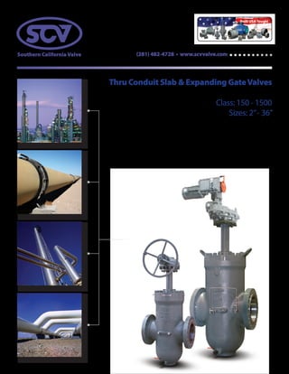
  • 1. (281) 482-4728 • www.scvvalve.com Thru Conduit Slab & Expanding GateValves Class: 150 - 1500 Sizes: 2”- 36”
  • 2. SOUTHERN CALIFORNIAVALVE manufactures some of the most dependable cast steelThru Conduit Slab and Expanding GateValves in the industry. Both designs utilize flanged and butt-weld end connections, and are manufactured and tested in accordance with API 6D. The full port design minimizes pressure drop and turbulence. The SCV design offers many features and options beneficial for oil, gas, and liquid applications making it the most demandedThru Conduit Gate on the market. Innovative valve solutions.®
  • 3. SCVThru Conduit Slab & Expanding GateValves [ Product Preview ] SCVTHRU CONDUIT SLAB GATE (BI-DIRECTIONAL) Pressure assisted seats for high pressure sealing Spring loaded seat for low pressure sealing Double block and bleed capabilities Internal pressure relieving through self relieving seats Secondary sealant injection at seats and stems Full port thru conduit for passage of pigs SCVTHRU CONDUIT EXPANDING GATE (BI-DIRECTIONAL)WITH PREFERRED PRESSURE SIDE Expanding mechanical gate forms positive tight sealing Seals at low and high pressure Double block and bleed capabilities Secondary sealant injections at seats and stems Optional by-pass system for thermal cavity relief venting Full port thru conduit for passage of pigs BASIC DESIGN API 6D FIRE SAFE DESIGN API 6FA FACETO FACE DIMENSION ANSI B16.10 FLANGE END DIMENSION ANSI B16.5 (2”to 24”) ANSI B16.47 & MSS SP-44 (26”& up) BUTT-WELD END DIMENSION ANSI B16.25 INSPECTION &TESTING API 6D Note: Not recommended for throttling applications. Note: SCV reserves the right to change any technical design and dimensional data without prior notice. Please contact SCV to confirm all Dimensions and Data offered in this catalog. For more information call us @ (281) 482-4728 or visit our website @ www.scvvalve.com
  • 4. Southern California Valve’s product lines include commodity valves as well as specialty valves in all Sizes, Pressure Classes & Metallurgy; including Carbon Steel, Stainless Steel & Exotic Alloys. The valve types include Gate, Globe, Swing Check - Bolted Bonnet & Pressure Seal Bonnet, Ball - floating, trunnion, rising stem, Thru-Conduit Gate - slab and expanding, Swing Check - Full and Regular Port, Lubricated Plugs, Dual Plate Checks - wafer and lug. Southern California Valve’s High Quality Standards demand 100% pressure testing of every valve to insure its reliability and full customer satisfaction. At Southern California Valve, we pride ourselves with high quality products in the commodity and specialty valve lines, as well as, timely deliveries, and competitive prices. Company History Southern California Valve was established in 1972. The primary focus of the Company was to provide full inline field service for valve maintenance as well as in house valve modifications. While serving the Power Industry, Paper & Pulp, Oil & Gas, and the Petro Chemical Industry; through years of dedication and commitment to quality and service, Southern California Valve has become one of the largest West Coast full range, field service companies, with a reputation for superior quality. In the mid 1970s, Southern California Valve entered the valve manufacturing industry, primarily serving the Power Industry. Since that time, Southern California Valve has expanded their products to cover a broad range of valves. Southern California Valve holds the API 6A & API 6D Monogram, API Q1 Quality Management System, and ASME“R”stamp. The Corporate office and manufacturing facility is located in Santa Fe Springs, California. The Sales and Projects office is located in Santa Fe, Texas. Mission Statement Southern California Valve is committed to consistently providing products that meet or exceed customer and regulatory specifications. SCV aims to enhance customer satisfaction through implementing the highest levels of quality standards while assuring full conformity to those requirements.
  • 5. Page Table of Contents................................................................................................................................................................................................................................1 Complete Product Line....................................................................................................................................................................................................................2 Certifications........................................................................................................................................................................................................................................3 • American Petroleum Institute (API) • ISO 9001:2008 • Canadian Registration Numbers • CE PED Figure Number Chart................................................................................................................................................................................................................4 & 5 Valve ID Tag & Valve Markings Identification..........................................................................................................................................................................6 THRU CONDUIT SLAB & EXPANDING GATE VALVES....................................................................................................................7 Thru Conduit Slab Gate Expanded View & Bill of Materials...............................................................................................................................................8 Slab Gate Advanced Mechanical Details..................................................................................................................................................................................9 Thru Conduit Expanding Gate Expanded View & Bill of Materials..............................................................................................................................10 Expanding Gate Advanced Mechanical Details..................................................................................................................................................................11 Slab & Expanding Gate Valve Dimensions 150 Class........................................................................................................................................................12 Slab & Expanding Gate Valve Dimensions 300 Class........................................................................................................................................................13 Slab & Expanding Gate Valve Dimensions 600 Class........................................................................................................................................................14 Slab & Expanding Gate Valve Dimensions 900 Class........................................................................................................................................................15 Slab & Expanding Gate Valve Dimensions 1500 Class......................................................................................................................................................16 Slab & Expanding Gate Valve Cv Values.................................................................................................................................................................................17 Expanding Gate Valve Thermal Relief System.....................................................................................................................................................................17 Slab Gate Valve Operator Interface..........................................................................................................................................................................................18 Expanding Gate Valve Operator Interface.............................................................................................................................................................................19 Pressure Temperature Ratings.................................................................................................................................................................................20, 21, & 22 Flange Dimensions...............................................................................................................................................................................................................23 & 24 Butt-welding Dimensions..................................................................................................................................................................................................25 & 26 Terms and Conditions....................................................................................................................................................................................................................27 Table of Contents
  • 6. 2 PRESSURE SEAL GATES Carbon & Stainless Sizes: 2”- 24” Class: 600 - 2500 Design: API 600 B16.34 BOLTED BONNET GLOBES Carbon & Stainless Sizes: 2”- 24” Class: 150 - 2500 Design: BS1873 B16.34 PRESSURE SEAL GLOBES Carbon & Stainless Sizes: 2”- 16” Class: 600 - 2500 Design: API623 B16.34 PRESSURE SEAL CHECKS Carbon & Stainless Sizes: 2”- 24” Class: 600 - 2500 Design: API 594 B16.34 LUBRICATED PLUGS Carbon Steel Sizes: 2”- 36” Class: 150 - 2500 Design: API 6D BOLTED BONNET GATES Carbon & Stainless Sizes: 2”- 60” Class: 150 - 2500 Design: API 600 COVER PISTON CHECKS Carbon Steel Bolted Sizes: 2”- 24” Class: 150 - 2500 Design: API 6D FLOATING BALL VALVES 1-PIECE REDUCED PORT 2-PIECE FULL PORT Carbon & Stainless Sizes: 1/2”- 12” Class: 150 - 1500 Design: B16.34 Complete Product Line Call SCV today @ (281) 482-4728 for all your valve needs or visit us on the web @ www.scvvalve.com. 3-PIECE TRUNNION BALLS BOLTED & WELDED BODY Carbon & Stainless Sizes: 2”- 42” Class: 150 - 2500 Design: API 6D 3-PIECE FULL PORT BALLS Carbon & Stainless Sizes: 1/4”- 3” Class: 3705W.O.G. Design: B16.34 DUAL PLATE CHECKSWAFER & LUG Carbon & Stainless Wafer Sizes: 1.5”- 36” Wafer Class: 150 - 2500 Lug Sizes: 2”- 36” Lug Class: 150 - 900 Design: API 594 BOLTED COVER FULL PORT SWING CHECKS Carbon & Stainless Sizes: 2”- 36” Class: 150 - 2500 Design: API 6D THRU CONDUIT - SLAB & EXPANDING GATES Carbon Steel Sizes: 2”- 36” Class: 150 - 1500 Design: API 6D 3-PIECE TRUNNION BALLS Carbon & Stainless Sizes: 2-1/16”- 13-5/8” Pressure: 2000, 3000 & 5000 Design: API 6A
  • 7. 3 American Petroleum Institute (API) Texas Facility: API 6A Certification California Facility: API 6A Certification Texas Facility: API 6D Certification California Facility: API 6D Certification Canadian Registration Number • Alberta - 0C07063.2 • New Brunswick - 0C07063.27 • New Foundland & Laborador - 0C07063.20 • Northwest Territory - 0C07063.25 • Novascotia - 0C07063.27 • Nunavut - 0C07063.2N • Manitoba - 0C07063.24 • Ontario - 0C07063.25 • Prince Edward island - 0C07063.29 • Yukon - 0C07063.2 Certifications & Registrations ISO 9001:2008 Certificate CE PED Certificate
  • 8. SCV Figure Number Chart ValveType Bore Size Pressure Class Body/Bonnet Body Material Trim Material BAL = Ball .50 = 1/2” .5 = 50 B = Bolted 01 = Cast Iron 90 = Titanium 10 = CR13 DBV = Double Ball Valve .07 = 9/16” .7 = 75 H = Bar Stock 02 = A352/LCC 91 = Tantalum 11 = CR13/HF DCK = Dual Wafer Check .08 = 13/16” 12 = 125 L = Lug 03 = A352/LC2 96 = Zirconium 12 = CR13 HF/HF DSP = Dual Seal Plug .75 = 3/4” 01 = 150 N = NRS Bolted 04 = CF8 13 = A105/ENP FCK = Full Port Check 01 = 1” 02 = 200 P = Pressure Seal 05 = Ductile 14 = Steel/Chrome GAT = Gate 1.2 = 1-1/16” 03 = 300 R = Threaded Body 06 = CF8M 15 = LF2/ENP GLB = Globe 1.3 = 1-1/8” 04 = 400 S = Seal Weld 08 = A216 WCC 16 = 416 PCK = Piston Check 1.4 = 1-1/4” 06 = 600 T = Top Entry 09 = WC9/F22 17 = 17 4-PH PLG = Plug 1.5 = 1-1/2” 08 = 800 U = Union 10 = A216 WCB 18 = LF3+ENP RSB = Rising Stem Ball 1.8 = 1-13/16” 09 = 900 W = Wafer 11 = A352 LCB 20 = Alloy 20 SCK = Swing Check 02 = 2” 11= 1000 Y = Y-Pattern 12 = A350 LF2 21 = Alloy 20/HF TCG = Thru Conduit Gate 2.2 = 2-1/16” 15 = 1500 13 = A105 22 = F-22 TCK = Tilting Disc Check 2.3 = 2-1/8” 17 = 175 14 = LC3/LF3 25 = Inconel Overlay WCK = Wafer Check 2.5 = 2-1/2” 20 = 2000 15 = A217 C5 28 = Sanicro 28 2.7 = 2-9/16” 25 = 2500 16 = WC6/F11 30 = 4130 03 = 3” 30 = 3000 17 = 17-4 PH 31 = 321 3.3 = 3-16” 37 = 3705 18 = A108 32 = 316L 04 = 4” 45 = 4500 19 = LF4 33 = 304/HF 4.2 = 4-1/16” 50 = 5000 20 = Alloy 20 34 = 304 05 = 05” 60 = 6000 21 = LF6 35 = 316/HF 06 = 06” 10 = 10000 22 = F-22 36 = 316 08 = 08” 05 = 15000 24 = 254 SMO 37 = 317/HF 10 = 10” 25 = F5 38 = 317 12 = 12” 26 = F91 39 = 1040 14 = 14” 27 = C12A 41 = 410/F6a 16 = 16” 28 = Sanicro 28 42 = Full Teflon 18 = 18” 29 = C12/F9 44 = F44 Duplex 20 = 20” 30 = AISI 4130 47 = 347 22 = 22” 31 = 321 48 = 347/HF 24 = 24” 32 = 321L 49 = Carpenter 26 = 26” 33 = 304L 50 = Monel 30 = 30” 34 = 304 51 = F51 Duplex 32 = 32” 35 = 316L 52 = Nickel Alloy 36 = 36” 36 = 316 53 = F53 Duplex 40 = 40” 37 = 317L 54 = A516/ENP 42 = 42” 38 = 317 55 = F55 Duplex 40 = AISI 4140 56 = A36/ENP 41 = 410/F6a 57 = A537/ENP 44 = F44 Duplex 60 = Duplex 47 = 347 61 = Super Duplex 48 = 347L 62 = Inconel 625 49 = Carpenter 63 = Inconel 600 50 = Monel 69 = Naval Brass 51 = F51 Duplex 70 = Bronze 52 = Nickel Alloy 71 = Aluminum 53 = F53 Duplex 78 = Inconel 718 54 = ASTM A516 80 = Alu/Brz 55 = F55 Duplex 81 = Ni Alu/Brz 56 = ASTM A36 82 = Inconel 825 57 = ASTM A537 83 = Hastelloy 60 = Duplex 86 = 8026 61 = Super Duplex 87 = 487 62 = Inconel 625 88 = A890-4A 63 = Inconel 600 89 = A890-5A 65 = F65 90 = Titanium 69 = Naval Brass 91 = Tantalum 70 = Bronze 92 = Inconel 925 71 = Aluminum 93 = Tungsten Carbide 78 = Inconel 718 96 = Zirconium 80 = Alu Bronze 97 = Nickel Boron 81 = Ni Alu/Brz 82 = Inconel 825 83 = Hastelloy B 84 = Hastelloy C 86 = AISI 8026 87 = 487 88 = A890-4A 89 = A890-5A Note: SCV Figure Chart is subject to change without notice. 1 2 3 4 5 6
  • 9. 5 5 6 9 10 11 124 7 821 3 Sample Figure Numbers & Descriptions ValveType Sample Figure # Description Trunnion Ball BAL0201B1313RLFT-HD Ball Valve, 2”, 150#, Bolted Bonnet, A105 Body, ENP Trim, HNBR Seals, Devlon Seats, Raised Face, Lever Operated, Full Port, Trunnion Mtd. Floating Ball BAL0201B1036RLFF-/T Ball Valve, 2”, 150#, Bolted Bonnet, A216 WCB Body, 316SS Trim, PTFE Seats, Raised Face, Lever Oper., Full Port, Floating Ball Dual Plate Wafer Check DCK0406W1035R Dual Plate Wafer Check, 4”, 600#, Wafer Style, A216 WCB Body, 316SS/HF Trim, Raised Face Full Port Swing Check FCK0409B1011J Full Port Swing Check, 4”, 900#, Bolted Bonnet, A216 WCB Body, Cr13/HF Trim, Ring Type Joint Wedge Gate GAT0303P1035RH Wedge Gate, 3”, 300#, Pressure Seal, WCB, 316SS/HF Trim, Raised Face, Hand Wheel Operated Globe GLB0803B1011RH Globe, 8”, 300#, Bolted Bonnet, WCB, Cr13/HF Trim, Raised Face, Hand Wheel Operated Swing Check SCK0601B1036R Swing Check, 6”, 150#, Bolted Bonnet, WCB, Cr13/HF Trim, Raised Face Lubricated Plug PLG0803B1041RL-VM Lubricated Plug Valve, 8”, 300#, Bolted Bonnet, WCB, 410SS Trim, Viton Seals, Hardface Seats, Raised Face, Lever Operated Dual Seal Plug DSP0803B1011RG Dual Seal Plug, 8”, 300#, bolted Bonnet, WCB, Cr13/HF Trim, Raised Face, Gear Operated Thru Conduit Gate TCG0603B1036RG-VM Thru Conduit Gate, 6”, 300#, Bolted Bonnet, WCB, 316SS Trim, Viton Seals, Hardface Seats, Raised Face, Gear Operated Expanding Gate TCG0603B1036RGEX-VM Thru Conduit Gate, 6”, 300#, Bolted Bonnet, WCB, 316SS Trim, Viton Seals, Hardface Seats, Raised Face, Gear Operated, Expanding Rising Stem Ball RSB1006B1036RGFT-HR Rising Stem Ball, 10”, 600#, Bolted Bonnet, WCB Body, 316SS Trim, HNBR Seals, RPTFE Seats, Raised Face, Gear Operated BAL 02 01 B 13 13 R L FT - H D X Figure Number Profile No. Figure Number Code Description 1 ValveType Identifies the valve body design (gate, globe, ball, plug, etc.) 2 Bore Size Identifies nominal port size (1/2”to 42”) 3 Pressure Class Identifies pressure classes ranging from 50 to 15,000 4 Body/Bonnet Identifies body and bonnet material configuration (bolted bonnet, pressure seal, top entry, etc.) 5 Body Material Identifies body material composition (A105,WCB, Stainless Steel, F51, etc.) 6 Trim Material Identifies trim material composition (ENP, 316, F6, Cr13, HF, etc.) 7 Ends Identifies end connection configuration (weld end, RTJ, socket weld, hub, etc.) 8 Operation Identifies valve operation mechanism (electric, gear, hydraulic, lever, etc.) 9 Configuration (ball & expanding gate only) Identifies valve configuration (floater, trunnion, etc.) 10 Seal Material Identifies seal material composition (Buna, EPDM, Grafoil, HNBR, Neoprene,Teflon, etc.) 11 Seat Material Identifies seat material composition (Devlon, Graphite, PCTFE, Nylon, PEEK,Teflon, etc.) 12 Special Identifies special treatments or configurations (when applicable) Note: Wedge Gates, Globes, Swing Checks, Piston Checks, Wafer Checks are metal-to-metal seats as standard. 7 8 9 10 11 12 Note: Subject to change without notice. Control #: MSF 3.5-16 rev 7 Ends Operation Configuration Seal Material Seat Material Special A = RF x BW B = Bare Stem 32 = 3 Way 2 Port 4 = 304 Ring D = Devlon By Pass B = RTJ x BW D = Dual Acting 3F = 3 Way Floater 6 = 316 Ring G = Graphite Cadium Coat C = Clamp E = Electric 3T = 3 Way Trunnion A = Aflas O-Ring K = PCTFE Cryogenic D = RF x RTJ G = Gear 43 = 4 Way 3 Port B = Buna M = Metal Seated Epoxy Paint F = Flat H = Handwheel 4F = 4 Way Floater E = EPDM N = Nylon Lip Seal H = Hub L = Lever 4T = 4 Way Trunnion F = Fluorosilicone O = Nova Metal Hardface J = RTJ O = Oil/Gas EX = Expanding G = Grafoil P = PEEK MetalTungsten Carbide N = Nipples S = S/Return FF = Full Floater H = HNBR R = RPTFE Nitride M = SW x TH Y = Hydraulic FT = Full Trunnion K = Kalrez T = Teflon Outside WT O = ODD RF = Red, Floater L = Lip Seal QPQ Inturnal R = RF RT = Red, Trunnion N = Neoprene Slam Retard S = SW SJ = Steam Jacket P = Polyuerethane Stancoat T = TH R = NBR Sub Sea W = WE S = Silicone Teflon Lined T = Teflon Top Extension U = Floursint Zinc Base V = Viton
  • 10. 6 No. Figure Number Code Description 1 Serial Number Identifies certified manufacturers serial number 2 Figure Number Identifies the detailed valve configuration (valve type, bore size, pressure class, materials, etc.) 3 MOP/Max.Temp. Identifies the maximum operating pressure in PSI and maximum operating temperature in Fahrenheit 4 Size Identifies bore size 5 Pressure Class Identifies pressure classifications per API requirements 6 Body Material Identifies body metal material composition (A105,WCB, F51, CF8M, etc.) 7 Stem Material Identifies stem material composition (A105, 410SS, 17-4pH, etc.) 8 Ball/Disc Material Identifies ball/disc material composition (A105, 316SS, ENP, etc.) 9 Seat Material Identifies seat material composition (PEEK,Teflon, Nylon, etc.) 10 MOP/Min.Temp. Identifies the maximum operating pressure in PSI and minimum operating temperature in Fahrenheit 11 Manufacturing Date Identifies the date the valve manufacturing completion date 12 API Conformance Identifies API conformance (600, 6D, 6A, etc.) 13 O Ring Identifies the O Ring material composition (Viton,Viton GLT, etc.) 14 NACE MR 01 75 Identifies corrosion resistance Note: SCV reserves the right to modify our products for improvement without prior notice. Valve IDTag &Valve Markings Identification 1 3 2 4 5 6 7 8 9 10 11 12 13 14 No. Valve ID Components 1 Tag 2 Brand 3 Size 4 Pressure Class 5 Body Material 6 Heat Number Valve Markings Valve IDTag 6 600 WCB T9123 3 2 1 4 5 6
  • 11. 7 Thru Conduit Slab & Expanding GateValves Class: 150 - 1500/Sizes: 2”- 36” Design and Manufacturing Standards Basic Design API 6D Face to Face Dimension ANSI B16.10 Flange End Dimension ANSI/ASME B16.5 (2”to 24”) ANSI/ASME B16.47 & MSS SP-44 (26”& up) Butt-Weld End Dimension ANSI/ASME B16.25 Inspection &Testing API 6D Fire Safe Design API 6FA
  • 12. 8 Thru Conduit Slab GateValve (Bi-Directional) [ Expanded View & Bill of Materials ] 4 19 20 23 8 2 11 7 10 14 17 3 21 18 22 24 15 15 13 16 12 25 26 6 9 Bill of Materials No. Part Material 1 Body ASTM A216WCC 2 Bonnet ASTM A105 3 Yoke Assembly ASTM A105/A106 4 Slab Disc WCC+ENP 5 Seat Ring A105+ENP+Nylon/RTFE 6 Seat O-Ring Viton AED 7 Bonnet Gasket 304 SS + Graphite 8 Stem 17 - 4 9 Body DrainValve Carbon Steel 10 Sealant Injector Fitting 316 SS 11 Bonnet Stud Bolt ASTM A193 B7M 12 Bonnet Nut ASTM A194 2HM 13 Stud Bolt ASTM A193 B7M 14 Packing Injector Fitting 316 SS 15 YokeVent Plug 316 SS 16 Vent 316 SS 17 Nut ASTM A194 2HM 18 Gear Operator Bolt ASTM A193 B7M 19 Packing Rings VITON/DUCK 20 Lantern Ring PEEK 21 Gear Operator / 22 Key Steel 23 Stem Protector Clear Plastic 24 Handwheel Steel 25 HandwheelWasher Steel 26 Handwheel Bolt Steel
  • 13. 9 Seats – Soft & Metal The spring loaded double O-ring design seats maintain a perfect seal with the gate in both low and high pressure applications. The soft seat inserts help to ensure that the primary sealing occurs at the gate. In the event of soft seat damage, the seating of metal to metal will function as a secondary seal. (Figure 1) Double Block When the valve is in the closed position and also has equal or no pressure, both spring loaded seats can shut off line pressure independently of upstream and downstream pressure. This creates a double block scenario. (Figure 2) When line pressure is applied, the pressure forces the slab gate to float against the downstream seat and form a tight seal. At the same time, the upstream line pressure forces the upstream seat on the slab gate to form an upstream seal. (Figure 3) Self Relieving Cavity The double block and bleed slab gate design, in the closed position, may experience an increase in cavity pressure due to thermal expansion. When the cavity pressure exceeds the line pressure, the seat is forced away from the gate surface allowing the excess cavity pressure to be vented into the line. This allows for a pressure balance between the body cavity and the line. The valve body presure will relieve to the lower differential side. (Figure 4) Secondary Sealant and Packing Injection System All valves will have secondary sealant injection fittings for the stem and seats. If the seat inserts or O-rings become damaged, leakage from the seat can be prevented by injecting sealant into the fittings. (Figure 5) Slab Gate Advanced Mechanical Details Through its simple design and efficient performance, the slab gate’s two spring loaded floating seats are pressure energized. This allows for complete sealing, both upstream and downstream. [ Features Overview ] Cavity Pressure Line Pressure Slab Body Seat Injection Seat O-ring Seat Insert Seat Ring Gate Stem Stem Injection Packing Lantern Ring Packing Bonnet Metal-to-metal Contact Slab Spring Body Seat Insert Seat RingSlab Seat O-ring Spring Body Seat Insert Seat RingSlab Seat O-ring Figure 1 Figure 2 Figure 3 Figure 4 Figure 5
  • 14. 10 23 24 27 11 2 15 10 13 9 14 18 21 3 25 22 26 28 19 8 7 1 5 4 6 17 20 16 29 30 12 Thru Conduit Expanding GateValve (Bi-Directional) with Preferred Pressure Side [ Expanded View & Bill of Materials ] Bill of Materials No. Part Material 1 Body ASTM A216WCC 2 Bonnet ASTM A105 3 Yoke Assembly ASTM A105/A106 4 Expanding Disc Gate WCC + ENP 5 Expanding Disc Segment WCC + ENP 6 Lever Lock Arm 4130 7 Seat Ring A105 + ENP + Nylon 8 Skirt ASTM A36 9 Seat O-Ring Viton AED 10 Bonnet Gasket 304 SS + Graphite 11 Stem 17 - 4 12 Body DrainValve Carbon Steel 13 Sealant Injector Fitting 316 SS 14 Vent Bypass Plug 316 SS 15 Bonnet Stud Bolt ASTM A193 B7M 16 Bonnet Nut ASTM A194 2HM 17 Stud Bolt ASTM A193 B7M 18 Packing Injector Fitting 316 SS 19 YokeVent Plug 316 SS 20 Vent 316 SS 21 Nut ASTM A194 2HM 22 Gear Operator Bolt ASTM A193 B7M 23 Packing Rings VITON/DUCK 24 Lantern Ring PEEK 25 Gear Operator / 26 Key Steel 27 Stem Protector Clear Plastic 28 Handwheel Steel 29 HandwheelWasher Steel 30 Handwheel Bolt Steel
  • 15. 11 Sealant Injector Fitting Disc Gate Disc Segment Disc Segment StopSeat Rings Preferred Flow Direction Preferred Flow Direction Preferred Flow Direction Full Expanded Closed In the full expanded closed position, the segment stop has engaged with the lower body stop and the gate is wedged downward, expanding the gate and segment to form a tight seal against the upstream and downstream seats. Body cavity venting will assist to provide tight shut off. (Figure 1) Mid Position When operating towards the open position, the gate travels across the wedge angle of the segment. This retracts the assembly so that is will slide freely between the seat faces. (Figure 2) Full Expanded Open In the full expanded open position, the segment stop has engaged the upper body stop and the gate is wedged upward. This expands the segment and the gate into the seats, isolating the flow from the cavity. (Figure 3) Expanding Gate Advanced Mechanical Details The SCV Expanding Gate valve design provides a mechanical seal between the seats and the gate in both high and low pressure applications. The expanding gate valve does not require line pressure to seal and is recommended when a tight mechanical seal is required. [ Features Overview ] Figure 1 Figure 2 Figure 3
  • 16. 12 G1 G2 GW L2L1 H1 H L H2 HW CLASS150 SIZE END-TO-END CENTER-TO-BOTTOM HANDWHEEL OPERATED GEAR OPERATED WEIGHTS LBS/KGRF - L BW - L1 H H1 H2 HW G1 G2 GW ADAPTER IN 2 7 / 5.50 19.04 11.72 10 / / / / 84 MM 50 178 / 140 484 298 254 / / / 38 IN 3 8 / 7.25 23.28 14.45 10.00 / / / / 113 MM 80 203 / 184 591 367 254 / / / 51 IN 4 9 / 8.50 25.4 16.90 10.00 25.4 16.90 10.00 FA10 MTG 125 MM 100 229 / 216 645 429 254 645 429 254 57 IN 6 10.5 / 11.50 32.3 21.70 18.00 32.3 21.70 12.00 FA10 MTG 226 MM 150 267 / 292 820 551 457 820 551 305 102 IN 8 11.5 / 15.25 41.48 27.88 18.00 41.48 27.88 12.00 FA14 MTG 426 MM 200 292 / 387 1054 708 457 1054 708 305 193 IN 10 13 / 18.13 49.84 33.54 24.00 49.84 33.54 12.00 FA14 MTG 707 MM 250 330 / 461 1266 852 610 1266 852 305 321 IN 12 14 / 22.00 57.6 39.11 24.00 57.6 39.11 18.00 FA14 MTG 850 MM 300 356 / 559 1463 993 610 1463 993 457 386 IN 14 15 / 25.25 / / / 60.81 41.42 18.00 FA14 MTG 1115 MM 350 381 / 641 / / / 1545 1052 457 506 IN 16 16 / 26.70 / / / 70.39 47.89 18.00 FA14 MTG 1816 MM 400 406 / 678 / / / 1788 1216 457 869 IN 18 17 / 31.375 / / / 76.21 51.31 18.00 FA16 MTG 1910 MM 450 432 / 797 / / / 1936 1303 457 866 IN 20 18 / 33.68 / / / 84.49 57.99 18.00 FA16 MTG 3244 MM 500 457 / 855 / / / 2146 1473 457 1471 IN 24 20 / 40.00 / / / 100.3 69.30 24.00 FA16 MTG 4867 MM 600 508 / 1016 / / / 2548 1760 610 1935 IN 30 26 / 50.38 / / / 121.13 83.93 24.00 FA16 MTG 9175 MM 750 660 / 1280 / / / 3077 2132 610 4162 IN 36 32 / 58.18 / / / 140.99 97.23 24.00 FA19 MTG 11727 MM 900 813 / 1478 / / / 3581 2470 610 5319 Slab & Expanding Gate Valve Dimensions Size: 2”- 36” Class: 150 Note: SCV reserves the right to change any technical design and dimensional data without prior notice. Please contact SCV to confirm all Dimensions and Data offered in this catalog.
  • 17. 13 G1 G2 GW L2L1 H1 H L H2 HW CLASS300 SIZE END-TO-END CENTER-TO-BOTTOM HANDWHEEL OPERATED GEAR OPERATED WEIGHTS LBS/KGRF - L BW - L1 H H1 H2 HW G1 G2 GW ADAPTER IN 2 8.50 / 5.70 19.04 11.72 10.00 / / / / 90 MM 50 216 / 145 484 298 254 / / / 41 IN 3 11.12 / 7.04 23.71 14.94 10.00 / / / / 160 MM 80 282 / 179 602 379 254 / / / 73 IN 4 12.00 / 8.63 26.21 16.63 10.00 / / / / 180 MM 100 304.8 / 219 666 422 254 / / / 82 IN 6 15.88 / 11.73 32.13 21.63 18.00 32.13 21.63 12.00 FA10 MTG 297 MM 150 403 / 298 816 549 457 816 549 305 135 IN 8 16.50 / 15.13 40.52 27.69 18.00 40.52 27.69 18.00 FA14 MTG 532 MM 200 419 / 384 1029 703 457 1029 703 457 241 IN 10 18.00 / 18.25 49.04 33.14 24.00 33.14 49.04 18.00 FA14 MTG 725 MM 250 457 / 464 1246 842 610 1246 842 457 329 IN 12 19.75 / 21.88 56.73 38.63 24.00 56.73 38.63 18.00 FA14 MTG 1280 MM 300 502 / 556 1441 981 610 1441 981 457 581 IN 14 30.00 / 23.79 / / / 60.82 41.42 18.00 FA14 MTG 1731 MM 350 762 / 604 / / / 1545 1052 457 785 IN 16 33.00 / 27.50 / / / 67.92 46.72 24.00 FA14 MTG 2262 MM 400 838 / 699 / / / 1725 1187 610 1026 IN 18 36.00 / 30.50 / / / 76.49 51.79 24.00 FA16 MTG 3184 MM 450 914 / 775 / / / 1943 1315 610 1444 IN 20 39.00 / 34.40 / / / 83.26 57.21 24.00 FA16 MTG 3825 MM 500 991 / 874 / / / 2114 1453 610 1735 IN 24 45.00 / 40.75 / / / 99.58 69.24 24.00 FA16 MTG 6090 MM 600 1143 / 1035 / / / 2529 1759 610 2762 IN 30 55.00 / 50.00 / / / 122.44 85.44 24.00 FA19 MTG 10180 MM 750 1397 / 1270 / / / 3110 2170 610 4618 Slab & Expanding Gate Valve Dimensions Size: 2”- 30” Class: 300 Note: SCV reserves the right to change any technical design and dimensional data without prior notice. Please contact SCV to confirm all Dimensions and Data offered in this catalog.
  • 18. 14 G1 G2 GW L2L1 H1 H L H2 HW Slab & Expanding GateValve Dimensions Size: 2”- 36” Class: 600 CLASS600 SIZE END-TO-END CNTR-TO-BTM HANDWHEEL OPERATED GEAR OPERATED WEIGHTS LBS/KGRF - L BW - L1 RTJ - L2 H H1 H2 HW G1 G2 GW ADAPTER IN 2 11.50 11.50 11.875 5.41 19.39 12.07 12.00 / / / / 124 MM 50 292 292 302 137 493 307 305 / / / 56 IN 3 14.00 14.00 14.12 7.03 23.76 14.94 12.00 / / / / 190 MM 80 356 356 359 178 604 379 305 / / / 86 IN 4 17.00 17.00 17.12 10.13 28.33 20.03 12.00 / / / / 335 MM 100 432 432 435 257 720 509 305 / / / 152 IN 6 22.00 22.00 22.12 12.75 36.52 25.16 18.00 / / 18.00 FA14 MTG 600 MM 150 559 559 562 323 928 639 457 / / 457 272 IN 8 26.00 26.00 26.12 17.13 46.44 31.94 24.00 / / 24.00 FA16 MTG 1050 MM 200 660 660 664 435 1180 811 610 / / 610 476 IN 10 31.00 31.00 31.12 21.25 75.14 37.74 24.00 / / 24.00 FA16 MTG 1920 MM 250 787 787 791 540 1909 959 610 / / 610 871 IN 12 33.00 33.00 33.12 23.50 / / / 62.82 43.12 24.00 FA25 MTG 2410 MM 300 838 838 841 597 / / / 1596 1095 610 1093 IN 14 35.00 35.00 35.12 26.75 / / / 68.02 46.02 30.00 FA25 MTG 3408 MM 350 889 889 892 679 / / / 1728 1169 762 1546 IN 16 39.00 39.00 39.12 29.50 / / / 74.95 51.75 30.00 FA25 MTG 4350 MM 400 991 991 994 749 / / / 1904 1314 762 1973 IN 18 43.00 43.00 43.12 33.12 / / / 80.13 56.93 30.00 FA25 MTG 5988 MM 450 1092 1092 1095 841 / / / 2035 1446 762 2716 IN 20 47.00 47.00 47.25 36.76 / / / 94.20 63.70 36.00 FA30 MTG 8458 MM 500 1194 1194 1200 934 / / / 2393 1618 914 3836 IN 22 51.00 51.00 51.38 40.75 / / / 103.83 70.53 36.00 FA35 MTG 10810 MM 550 1295 1295 1305 1035 / / / 2637 1791 914 4903 IN 24 55.00 55.00 55.38 44.50 / / / 111.20 76.30 36.00 FA35 MTG 13250 MM 600 1397 1397 1407 1130 / / / 2824 1938 914 6010 IN 26 57.00 57.00 57.5 48.63 / / / 117.94 81.34 36 FA35 MTG 16194 MM 650 1448 1448 1461 1235 / / / 2996 2066 914 7345 IN 30 65.00 65.00 65.5 54.00 / / / 131.66 91.66 36.00 FA35 MTG 21475 MM 750 1651 1651 1664 1372 / / / 3344 2328 914 9741 IN 36 82.00 82.00 85.62 63.50 / / / 180.76 105.88 36.00 FA35 MTG 34350 MM 900 2083 2083 2175 1613 / / / 4591 2689 914 15581 Note: SCV reserves the right to change any technical design and dimensional data without prior notice. Please contact SCV to confirm all Dimensions and Data offered in this catalog.
  • 19. 15 G1 G2 GW L2L1 H1 H L H2 HW Slab & Expanding GateValve Dimensions Size: 2”- 24” Class: 900 CLASS900 SIZE END-TO-END CNTR-TO-BTM HANDWHEEL OPERATED GEAR OPERATED WEIGHTS LBS/KGRF - L BW - L1 RTJ - L2 H H1 H2 HW G1 G2 GW ADAPTER IN 2 14.5 14.5 14.875 5.063 17.75 18.44 12.00 / / / / 185 MM 50 368 368 378 129 451 468 305 / / / 84 IN 3 15 15 15.12 7.04 23.76 14.94 18.00 / / / / 220 MM 80 381 381 384 179 604 379 457 / / / 100 IN 4 18 18 18.12 10.02 29.42 20.03 18.00 / / / FA14 MTG 400 MM 100 457 457 460 255 747 509 457 / / / 181 IN 6 24 24 24.12 13.13 36.56 25.16 18.00 / / / FA14 MTG 790 MM 150 610 610 613 334 929 639 457 / / / 358 IN 8 29 29 29.12 17.50 46.29 31.94 24.00 / / / FA16 MTG 1350 MM 200 737 737 740 445 1176 811 610 / / / 612 IN 10 33 33 33.12 21.75 / / / 55.14 37.74 24.00 FA16 MTG 2375 MM 250 838 838 841 552 / / / 1401 959 610 1077 IN 12 38 38 38.12 24.38 / / / 62.83 43.13 24.00 FA25 MTG 3394 MM 300 965 965 968 619 / / / 1596 1096 610 1539 IN 14 40.5 40.5 40.88 27.88 / / / 67.44 45.94 30.00 FA25 MTG 4170 MM 350 1029 1029 1038 708 / / / 1713 1167 762 1891 IN 16 44.5 44.5 44.88 30.00 / / / 74.95 51.75 30.00 FA25 MTG 5530 MM 400 1130 1130 1140 762 / / / 1904 1314 762 2508 IN 18 48 48 48.5 33.62 / / / 84.73 56.93 30.00 FA25 MTG 7294 MM 450 1219 1219 1232 854 / / / 2152 1446 762 3309 IN 20 52 52 52.5 37.90 / / / 97.11 70.56 36.00 FA30 MTG 11518 MM 500 1321 1321 1334 963 / / / 2467 1792 914 5224 IN 24 61 61 61.75 45.50 / / / 111.70 76.80 36.00 FA35 MTG 17673 MM 600 1549 1549 1568 1156 / / / 2837 1951 914 8016 Note: SCV reserves the right to change any technical design and dimensional data without prior notice. Please contact SCV to confirm all Dimensions and Data offered in this catalog.
  • 20. 16 G1 G2 GW L2L1 H1 H L H2 HW Slab & Expanding GateValve Dimensions Size: 2”- 12” Class: 1500 CLASS1500 SIZE END-TO-END CNTR-TO-BTM HANDWHEEL OPERATED GEAR OPERATED WEIGHTS LBS/KGRF - L BW - L1 RTJ - L2 H H1 H2 HW G1 G2 GW ADAPTER IN 2 14.5 14.5 14.875 5.062 17.75 18.44 12.00 / / / / 108 MM 50 368 368 378 129 451 468 305 / / / 49 IN 3 18.5 18.5 18.875 7.313 23.875 19.56 12.00 / / / / 248 MM 80 356 356 479 186 606 470 305 / / / 112 IN 4 21.5 21.5 21.875 9.062 28.50 24.75 18.00 / / / / 332 MM 100 546 546 556 230 724 629 457 / / / 151 IN 6 27.75 27.75 28 12.88 / / / 31.50 29.13 24.00 / 998 MM 150 705 705 711 327 / / / 800 740 610 453 IN 8 32.75 32.75 33.125 18.25 / / / 44.38 41.06 24.00 / 2435 MM 200 832 832 842 464 / / / 1127 1043 610 1104 IN 10 39.00 39.00 39.625 21.75 / / / 53.22 46.16 24.00 / 4002 MM 250 991 991 1000 552 / / / 1352 1172 610 1815 IN 12 44.50 44.50 45.00 24.56 / / / 57.72 53.41 30.00 / 5875 MM 300 1130 1130 1146 624 / / / 1466 1357 762 2667 Note: SCV reserves the right to change any technical design and dimensional data without prior notice. Please contact SCV to confirm all Dimensions and Data offered in this catalog. Adapter information available upon request.
  • 21. 17 Slab & Expanding GateValve CvValues The flow co-efficiency (Cv) of a valve is the rate of gallons per minute of water at 60° F through a fully opened valve at a pressure drop of 1 PSI across the valve. Expanding GateThermal Relief System With the expanding gate design, it is possible for Thermal Expansion to occur within the body cavity while the valve is in the closed position. A Thermal Relief system allows the body cavity to relieve into the upstream side of the valve. SIZE 300 600 900 1500 2500 2 432 378 337 337 218 3 x 2 / 165 203 239 / 2.5 / 682 558 558 305 3 1155 1109 1072 966 474 4 x 3 / 529 597 677 624 4 2176 1944 1890 1730 725 6 x 4 / 944 943 1231 / 6 5300 4577 4383 3622 2510 8 x 6 2499 3240 3588 2137 / 8 11054 8886 8416 6879 5227 10 x 8 5218 5036 7975 4859 / 10 18856 14533 14087 11283 8313 12 28980 22729 21025 16843 12282 14 30883 28837 23846 20336 / 16 42224 39144 33358 27548 21396 18 55740 51368 45004 / / 20 70386 64559 56871 / / 22 86869 80279 / / / 24 106835 97240 84836 / / 26 123222 114905 / / / 28 114355 135267 / / / 30 170229 157401 133706 / / 36 245362 224424 / / / Sample Thermal Relief Configuration Preferred Flow Direction SCV installedThermal Relief system on 16”Class 600 Thru Conduit Expanding Gate Valve.
  • 22. 18 Expanding GateValve Operator Interface Valve Size ANSI Class StemThread Top of Stem Closed Top of Stem Open Total Travel To Center ofValve Mtg Plt O.D. Bolt Circle Flange Pilot Dia. Mounting Holes Flange Pilot Depth Mtg Plt Thickness ISO/MSS Mtg Pattern A B C D E F G H J K L 4 600 1-1/4-5TPI-2G-LH 4.70 9.58 4.88 20.03 7.00 5.50 3.98 4 X 0.75 0.18 1.00 FA14 4 900 1-1/4-5TPI-2G-LH 4.60 9.48 4.88 20.15 7.00 5.50 3.98 4 X 0.75 0.18 1.00 FA14 6 150 1-5TPI-2G-LH 4.00 10.90 6.90 21.70 5.00 4.02 2.78 4 X 0.50 0.15 0.43 FA10 6 600 1-1/2-4TPI-2G-LH 4.50 11.35 6.85 25.42 7.00 5.50 3.98 4 X 0.75 0.18 1.00 FA14 6 900 1-1/2-4TPI-2G-LH 4.50 11.35 6.85 25.42 7.00 5.50 3.98 4 X 0.75 0.18 1.00 FA14 8 150 1-1/2-4TPI-2G-LH 4.40 13.65 9.25 27.88 6.75 5.50 3.98 4 X 0.69 0.18 0.70 FA14 8 600 1-3/4-4TPI-2G-LH 5.20 14.58 9.38 32.27 8.00 6.50 5.15 4 X 0.81 0.23 1.15 FA16 8 900 1-3/4-4TPI-2G-LH 4.90 14.28 9.38 32.57 8.00 6.50 5.15 4 X 0.81 0.23 1.15 FA16 10 150 1-1/2-4TPI-2G-LH 5.10 16.40 11.30 33.54 6.75 5.50 3.98 4 X 0.69 0.18 0.70 FA14 10 600 2-4TPI-2G-LH 5.70 17.40 11.70 37.74 8.50 6.50 5.15 4 X 0.88 0.25 1.13 FA16 10 900 2-4TPI-2G-LH 5.70 17.40 11.70 37.74 8.50 6.50 5.15 4 X 0.88 0.25 1.13 FA16 12 150 1-1/2-4TPI-2G-LH 5.40 18.60 13.20 39.11 6.75 5.50 3.98 4 X 0.69 0.18 0.70 FA14 12 600 2-1/4-3TPI-2G-LH 6.10 19.70 13.60 43.13 11.50 10.00 7.90 8 X 0.75 0.25 1.25 FA25 12 900 2-1/4-3TPI-2G-LH 6.10 19.70 13.60 43.13 11.50 10.00 7.90 8 X 0.75 0.25 1.25 FA25 14 600 2-1/2-3TPI-2G-LH 6.70 21.85 15.15 46.02 11.50 10.00 7.90 8 X 0.75 0.25 1.25 FA25 14 900 2-1/2-3TPI-2G-LH 6.70 21.50 15.20 45.94 11.50 10.00 7.90 8 X 0.75 0.25 1.25 FA25 16 150 *1.5-0.2P-0.40L- ACME-2G-LH 6.00 22.64 16.64 47.89 6.75 5.50 3.98 4 X 0.69 0.18 0.70 FA14 16 600 2-1/2-3TPI-2G-LH 6.50 23.15 16.65 51.75 12.00 10.00 7.90 8 X 0.75 0.25 1.25 FA25 16 900 2-1/2-3TPI-2G-LH 6.50 23.15 16.65 51.75 12.00 10.00 7.90 8 X 0.75 0.25 1.25 FA25 18 600 3-2TPI-2G-LH 9.20 28.23 19.03 56.93 12.00 10.00 7.90 8 X 0.75 0.25 1.25 FA25 18 900 3-2TPI-2G-LH 9.20 28.23 19.03 56.93 12.00 10.00 7.90 8 X 0.75 0.25 1.25 FA25 20 150 *2.0-0.25P-0.50L- ACME-2G-LH 6.00 26.50 20.50 57.99 8.25 6.50 5.15 4 X 0.81 0.23 1.15 FA16 20 600 3-1/4-2.5TPI-2G-LH 9.50 30.50 21.00 63.70 14.00 11.75 9.10 8 X 0.88 0.25 1.39 FA30 20 900 3-1/4-2.5TPI-2G-LH 8.90 29.90 21.00 64.20 14.00 11.75 9.10 8 X 0.88 0.25 1.39 FA30 22 600 3-1/4-2.5TPI-2G-LH 9.50 32.80 23.30 70.54 16.00 14.00 10.28 8 X 1.13 0.25 1.25 FA35 24 150 *2.0-0.25P-0.50L- ACME-2G-LH 6.50 31.30 24.80 69.30 8.25 6.50 5.15 4 X 0.81 0.23 0.75 FA16 24 600 4-2TPI-2G-LH 9.60 34.90 25.30 76.30 16.00 14.00 10.28 8 X 1.13 0.25 1.25 FA35 24 900 4-2TPI-2G-LH 9.10 34.40 25.30 76.80 16.00 14.00 10.28 8 X 1.13 0.25 1.25 FA35 26 600 4-2TPI-2G-LH 9.70 36.60 26.90 81.35 16.00 14.00 10.28 8 X 1.13 0.25 1.25 FA35 30 150 *2.5-0.25P-0.50L- ACME-2G-LH 6.90 37.65 30.75 83.93 8.25 6.50 5.15 4 X 0.81 0.23 0.75 FA16 30 600 4-2TPI-2G-LH 8.90 39.70 30.80 91.66 16.00 14.00 10.28 8 X 1.13 0.25 1.25 FA35 36 150 *2.5-0.25P-0.50L- ACME-2G-LH 6.70 42.70 36.00 97.89 9.00 7.50 5.64 8 X 0.69 0.23 0.75 FA19 36 600 4-2TPI-2G-LH 11.40 47.50 36.10 105.88 16.00 14.00 10.28 8 X 1.13 0.25 1.25 FA35 *Double LeadThread 1/4”- NPT B C D J F G H K L E A Operator Interface Dimensions
  • 23. 19 Slab GateValve Operator Interface Valve Size ANSI Class StemThread Top of Stem Closed Top of Stem Open Total Travel To Center ofValve Mtg Plt O.D. Bolt Circle Flange Pilot Dia. Mounting Holes Flange Pilot Depth Mtg Plt Thickness ISO/MSS Mtg Pattern A B C D E F G H J K L 4 600 1-1/4-5TPI-2G-LH 4.92 9.82 4.90 20.03 7.00 5.50 3.98 4 X 0.75 0.18 1.00 FA14 4 900 1-1/4-5TPI-2G-LH 4.92 9.70 4.78 20.15 7.00 5.50 3.98 4 X 0.75 0.18 1.00 FA14 6 150 1-5TPI-2G-LH 3.70 10.45 6.75 21.63 5.00 4.02 2.78 4 X 0.50 0.15 0.43 FA10 6 300 1-5TPI-2G-LH 3.70 10.45 6.75 21.63 5.00 4.02 2.78 4 X 0.50 0.15 0.43 FA10 6 600 1-1/2-4TPI-2G-LH 5.00 11.85 6.85 25.42 7.00 5.50 3.98 4 X 0.75 0.18 1.00 FA14 6 900 1-1/2-4TPI-2G-LH 5.00 11.58 6.85 25.42 7.00 5.50 3.98 4 X 0.75 0.18 1.00 FA14 8 150 1-1/2-4TPI-2G-LH 4.30 13.13 8.83 27.69 6.75 5.50 3.98 4 X 0.69 0.18 0.70 FA14 8 300 1-1/2-4TPI-2G-LH 4.30 13.13 8.83 27.69 6.75 5.50 3.98 4 X 0.69 0.18 0.70 FA14 8 600 1-3/4-4TPI-2G-LH 5.80 15.18 9.38 32.27 8.00 6.50 5.15 4 X 0.81 0.23 1.15 FA16 8 900 1-3/4-4TPI-2G-LH 5.50 14.88 9.38 32.57 8.00 6.50 5.15 4 X 0.81 0.23 1.15 FA16 10 150 1-1/2-4TPI-2G-LH 5.10 15.98 10.88 33.14 6.75 5.50 3.98 4 X 0.69 0.19 0.70 FA14 10 300 1-1/2-4TPI-2G-LH 5.10 15.98 10.88 33.14 6.75 5.50 3.96 4 X 0.69 0.19 0.70 FA14 10 600 2-4TPI-2G-LH 6.50 18.00 11.50 37.74 8.50 6.50 5.15 4 X 0.88 0.25 1.13 FA16 10 900 2-4TPI-2G-LH 6.50 18.00 11.50 33.74 8.50 6.50 5.15 4 X 0.88 0.25 1.13 FA16 12 150 1-1/2-4TPI-2G-LH 5.10 18.10 13.00 38.63 6.75 5.50 3.98 4 X 0.69 0.19 0.70 FA14 12 300 1-1/2-4TPI-2G-LH 5.10 18.10 13.00 38.63 6.75 5.50 3.98 4 X 0.69 0.19 0.70 FA14 12 600 2-1/4-3TPI-2G-LH 6.90 20.15 13.25 43.13 11.50 10.00 7.90 8 X 0.75 0.25 1.25 FA25 12 900 2-1/4-3TPI-2G-LH 6.90 20.15 13.25 43.13 11.50 10.00 7.90 8 X 0.75 0.25 1.25 FA25 14 150 *1.5-0.20P-040L- ACME-2G-LH 5.10 19.39 14.29 41.42 6.75 5.50 3.98 4 X 0.69 0.23 0.70 FA14 14 600 2-1/2-3TPI-2G-LH 7.30 22.30 15.00 45.94 11.50 10.00 7.90 8 X 0.75 0.25 1.25 FA25 14 900 2-1/2-3TPI-2G-LH 7.30 22.30 15.00 45.94 11.50 10.00 7.90 8 X 0.75 0.25 1.25 FA25 16 150 *1.5-0.20P-0.40L- ACME-2G-LH 6.10 22.28 16.18 46.73 6.75 5.50 3.98 4 X 0.69 0.19 0.70 FA14 16 300 *1.5-0.20P-040L- ACME2G-LH 6.10 21.28 16.18 46.79 6.75 5.50 3.98 4 X 0.69 0.19 0.70 FA14 16 600 2-1/2-3TPI-2G-LH 7.30 23.80 16.50 51.75 12.00 10.00 7.90 8 X 0.75 0.25 1.25 FA25 16 900 2-1/2-3TPI-2G-LH 7.30 23.80 16.50 51.75 12.00 10.00 7.90 8 X 0.75 0.25 1.25 FA25 18 600 3-2TPI-2G-LH 10.20 28.86 18.66 56.56 12.00 10.00 7.90 8 X 0.75 0.25 1.25 FA25 18 900 3-2TPI-2G-LH 10.20 28.86 18.66 56.56 12.00 10.00 7.90 8 X 0.75 0.25 1.25 FA25 20 150 *2.0-0.25P-0.50L- ACME-2G-LH 6.00 26.25 20.25 57.09 8.25 6.50 5.15 4 X 0.81 0.25 0.75 FA16 20 300 *2.0-0.25P-0.50L- ACME-2G-LH 5.80 26.05 20.25 57.21 8.25 6.50 5.15 4 X 0.81 0.25 0.75 FA16 20 600 3-1/4-2.5TPI-2G-LH 9.40 30.50 21.10 63.70 14.00 11.75 9.10 8 X 0.88 0.25 1.39 FA30 20 900 3-1/4-2.5TPI-2G-LH 9.50 30.00 20.50 64.20 14.00 11.75 9.10 8 X 0.88 0.25 1.39 FA30 22 600 3-1/4-2.5TPI-2G-LH 10.00 33.30 23.30 70.54 16.00 14.02 10.28 8 X 1.13 0.25 1.25 FA35 24 150 *2.0-0.25P-0.50L- ACME-2G-LH 6.50 31.00 24.50 68.61 8.25 6.50 5.15 4 X 0.81 0.23 0.75 FA16 24 300 *2.0-0.25P-0.50L- ACME-2G-LH 5.90 30.35 24.45 69.24 8.25 6.50 5.15 4 X 0.81 0.23 0.75 FA16 24 600 4-2TPI-2G-LH 10.10 35.43 25.33 76.30 16.00 14.00 10.28 8 X 1.13 0.25 1.25 FA35 24 900 4-2TPI-2G-LH 9.10 34.40 25.30 76.80 16.00 14.00 10.28 8 X 1.13 0.25 1.25 FA35 26 600 4-2TPI-2G-LH 11.00 37.86 26.86 81.35 16.00 14.00 10.28 8 X 1.13 0.25 1.25 FA35 30 150 *2.5-0.25P-0.50L- ACME-2G-LH 6.70 37.00 30.30 83.98 8.25 6.50 5.15 4 X 0.81 0.23 0.75 FA16 30 300 *2.5-0.25P-0.50L- ACME-2G-LH 6.70 37.00 30.30 85.44 9.00 7.50 5.64 8 X 0.69 0.23 0.75 FA19 30 600 4-2TPI-2G-LH 9.50 40.50 31.00 91.66 16.00 14.00 10.28 8 X 1.13 0.25 1.25 FA35 36 150 *2.5-0.25P-0.50L- ACME-2G-LH 6.40 42.15 35.75 97.23 9.00 7.50 5.64 8 X 0.69 0.23 0.75 FA19 36 600 4-2TPI-2G-LH 11.70 48.20 36.50 105.88 16.00 14.00 10.28 8 X 1.13 0.25 1.25 FA35 *Double LeadThread
  • 24. 20 PressureTemperature Ratings - ASME B16.34 Note: Pressures in PSI150 Temp. F A105 WCB LF2 WCC LCB WC6 LCC C5 C12 C12A 316 CF8M F51 F53 -20 to 100 285 285 285 290 265 290 290 290 290 290 275 275 290 290 200 260 260 260 260 255 260 260 260 260 260 235 235 260 260 300 230 230 230 230 230 230 230 230 230 230 215 215 230 230 400 200 200 200 200 200 200 200 200 200 200 195 195 200 200 500 170 170 170 170 170 170 170 170 170 170 170 170 170 170 600 140 140 140 140 140 140 140 140 140 140 140 140 140 140 650 125 125 125 125 125 125 125 125 125 125 125 125 125 125 700 110 110 110 110 110 110 110 110 110 110 110 110 110 110 750 95 95 95 95 95 95 95 95 95 95 95 95 95 95 800 80 80 80 80 80 80 80 80 80 80 80 80 / / 850 65 65 65 65 65 65 65 65 65 65 65 65 / / 900 50 50 50 50 50 50 50 50 50 50 50 50 / / 950 35 35 35 35 35 35 35 35 35 35 35 35 / / 1000 20 20 20 20 20 20 20 20 20 20 20 20 / / 1050 / / / / / 20 / 20 20 20 20 20 / / 1100 / / / / / 20 / 20 20 20 20 20 / / 1150 / / / / / 20 / 20 20 20 20 20 / / 1200 / / / / / 15 / 15 20 20 20 20 / / 1250 / / / / / / / / / / 20 20 / / 1300 / / / / / / / / / / 20 20 / / 1350 / / / / / / / / / / 20 20 / / 1400 / / / / / / / / / / 20 20 / / 1450 / / / / / / / / / / 20 20 / / 1500 / / / / / / / / / / 15 15 / / 300 Temp. F A105 WCB LF2 WCC LCB WC6 LCC C5 C12 C12A 316 CF8M F51 F53 -20 to 100 740 740 740 750 695 750 750 750 750 750 720 720 750 750 200 680 680 680 750 660 750 750 750 750 750 620 620 745 745 300 655 655 655 730 640 720 730 730 730 730 560 560 665 665 400 635 635 635 705 615 695 705 705 705 705 515 515 615 615 500 605 605 605 665 585 665 665 665 665 665 480 480 580 580 600 570 570 570 605 550 605 605 605 605 605 450 450 555 555 650 550 550 550 590 535 590 590 590 590 590 440 440 545 545 700 530 530 530 555 510 570 555 570 570 570 435 435 540 540 750 505 505 505 505 475 530 505 530 530 530 425 425 530 530 800 410 410 410 410 390 510 410 510 510 510 420 420 / / 850 320 320 320 320 300 485 320 485 485 485 420 420 / / 900 230 230 230 225 200 450 225 375 450 450 415 415 / / 950 135 135 135 135 135 320 135 275 375 385 385 385 / / 1000 85 85 85 85 85 215 85 200 255 365 365 365 / / 1050 / / / / / 145 / 145 170 360 160 160 / / 1100 / / / / / 95 / 100 115 300 305 305 / / 1150 / / / / / 65 / 60 75 225 235 235 / / 1200 / / / / / 40 / 35 50 145 185 185 / / 1250 / / / / / / / / / / 145 145 / / 1300 / / / / / / / / / / 115 115 / / 1350 / / / / / / / / / / 95 95 / / 1400 / / / / / / / / / / 75 75 / / 1450 / / / / / / / / / / 60 60 / / 1500 / / / / / / / / / / 40 40 / /
  • 25. 21 PressureTemperature Ratings - ASME B16.34 Note: Pressures in PSI600 Temp. F A105 WCB LF2 WCC LCB WC6 LCC C5 C12 C12A 316 CF8M F51 F53 -20 to 100 1480 1480 1480 1500 1395 1500 1500 1500 1500 1500 1440 1440 1500 1500 200 1360 1360 1360 1500 1320 1500 1500 1500 1500 1500 1240 1240 1490 1490 300 1310 1310 1310 1455 1275 1445 1455 1455 1455 1455 1120 1120 1335 1335 400 1265 1265 1265 1405 1230 1385 1405 1410 1410 1410 1025 1025 1230 1230 500 1205 1205 1205 1330 1175 1330 1330 1330 1330 1330 995 995 1160 1160 600 1135 1135 1135 1210 1105 1210 1210 1210 1210 1210 900 900 1115 1115 650 1100 1100 1100 1175 1065 1175 1175 1175 1175 1175 885 885 1095 1095 700 1060 1060 1060 1110 1025 1135 1110 1135 1135 1135 870 870 1085 1085 750 1015 1015 1015 1015 955 1065 1015 1065 1065 1065 855 855 1065 1065 800 825 825 825 825 780 1015 825 1015 1015 1015 845 845 / / 850 640 640 640 640 595 975 640 975 975 975 835 835 / / 900 460 460 460 445 405 900 445 745 900 900 830 830 / / 950 275 275 275 275 275 640 275 550 755 775 775 775 / / 1000 170 170 170 170 170 430 170 400 505 725 725 725 / / 1050 / / / / / 290 / 290 345 720 720 720 / / 1100 / / / / / 190 / 200 225 605 610 610 / / 1150 / / / / / 130 / 125 150 445 475 475 / / 1200 / / / / / 80 / 70 105 290 370 370 / / 1250 / / / / / / / / / / 295 295 / / 1300 / / / / / / / / / / 235 235 / / 1350 / / / / / / / / / / 190 190 / / 1400 / / / / / / / / / / 150 150 / / 1450 / / / / / / / / / / 115 115 / / 1500 / / / / / / / / / / 85 85 / / 900 Temp. F A105 WCB LF2 WCC LCB WC6 LCC C5 C12 C12A 316 CF8M F51 F53 -20 to 100 2220 2220 2220 2250 2090 2250 2250 2250 2250 2250 2160 2160 2250 2250 200 2035 2035 2035 2250 1980 2250 2250 2250 2250 2250 1860 1860 2230 2230 300 1965 1965 1965 2185 1915 2165 2185 2185 2185 2185 1680 1680 2000 2000 400 1900 1900 1900 2110 1845 2080 2110 2115 2115 2115 1540 1540 1845 1845 500 1810 1810 1810 1995 1760 1995 1995 1995 1995 1995 1435 1435 1740 1740 600 1705 1705 1705 1815 1655 1815 1815 1815 1815 1815 1355 1355 1670 1670 650 1650 1650 1650 1765 1600 1765 1765 1765 1765 1765 1325 1325 1640 1640 700 1590 1590 1590 1665 1535 1705 1665 1705 1705 1705 1305 1305 1625 1625 750 1520 1520 1520 1520 1430 1595 1520 1595 1595 1595 1280 1280 1595 1595 800 1235 1235 1235 1235 1175 1525 1235 1525 1525 1525 1265 1265 / / 850 955 955 955 955 895 1460 955 1460 1460 1460 1255 1255 / / 900 690 690 690 670 605 1350 670 1120 1350 1350 1245 1245 / / 950 410 410 410 410 410 955 410 825 1130 1160 1160 1160 / / 1000 255 255 255 255 255 650 255 595 760 1090 1090 1090 / / 1050 / / / / / 430 / 430 515 1080 1080 1080 / / 1100 / / / / / 290 / 300 340 905 915 915 / / 1150 / / / / / 195 / 185 225 670 710 710 / / 1200 / / / / / 125 / 105 155 430 555 555 / / 1250 / / / / / / / / / / 440 440 / / 1300 / / / / / / / / / / 350 350 / / 1350 / / / / / / / / / / 290 290 / / 1400 / / / / / / / / / / 225 225 / / 1450 / / / / / / / / / / 175 175 / / 1500 / / / / / / / / / / 125 125 / /
  • 26. 22 ASTM # 1500 Temp. F A105 WCB LF2 WCC LCB WC6 LCC C5 C12 C12A 316 CF8M F51 F53 -20 to 100 3705 3705 3705 3750 3480 3750 3750 3750 3750 3750 3600 3600 3750 3750 200 3395 3395 3395 3750 3300 3750 3750 3750 3750 3750 3095 3095 3720 3720 300 3270 3270 3270 3640 3190 3610 3640 3640 3640 3640 2795 2795 3335 3335 400 3170 3170 3170 3520 3075 3465 3520 3530 3530 3530 2570 2570 3070 3070 500 3015 3015 3015 3325 2930 3325 3325 3325 3325 3325 2390 2390 2905 2905 600 2840 2840 2840 3025 2755 3025 3025 3025 3025 3025 2255 2255 2785 2785 650 2745 2745 2745 2940 2665 2940 2940 2940 2940 2940 2210 2210 2735 2735 700 2665 2665 2665 2775 2560 2840 2775 2840 2840 2840 2170 2170 2710 2710 750 2535 2535 2535 2535 2385 2660 2535 2660 2660 2660 2135 2135 2660 2660 800 2055 2055 2055 2055 1955 2540 2055 2540 2540 2540 2110 2110 / / 850 1595 1595 1595 1595 1490 2435 1595 2435 2435 2435 2090 2090 / / 900 1150 1150 1150 1115 1010 2245 1115 1870 2245 2245 2075 2075 / / 950 685 685 685 685 685 1591 685 1370 1885 1930 1930 1930 / / 1000 430 430 430 430 430 1080 430 995 1270 1820 1820 1820 / / 1050 / / / / / 720 / 720 855 1800 1800 1800 / / 1100 / / / / / 480 / 495 565 1510 1525 1525 / / 1150 / / / / / 325 / 310 375 1115 1185 1185 / / 1200 / / / / / 205 / 170 255 720 925 925 / / 1250 / / / / / / / / / / 735 735 / / 1300 / / / / / / / / / / 585 585 / / 1350 / / / / / / / / / / 480 480 / / 1400 / / / / / / / / / / 380 380 / / 1450 / / / / / / / / / / 290 290 / / 1500 / / / / / / / / / / 205 205 / / 2500 Temp. F A105 WCB LF2 WCC LCB WC6 LCC C5 C12 C12A 316 CF8M F51 F53 -20 to 100 6170 6170 6170 6250 5805 6250 6250 6250 3250 6250 6000 6000 6250 6250 200 5655 5655 5655 6250 5505 6250 6250 6250 6250 6250 5160 5160 6200 6200 300 5450 5450 5450 6070 5315 6015 6070 6070 6070 6070 4660 4660 5560 5560 400 5280 5280 5280 5865 5125 5775 5865 5880 5880 5880 4280 4280 5120 5120 500 5025 5025 5025 5540 4885 5540 5540 5540 5540 5540 3980 3980 4840 4840 600 4730 4730 4730 5040 4595 5040 5040 5040 5040 5040 3760 3760 4640 4640 650 4575 4575 4575 4905 4440 4905 4905 4905 4905 4905 3680 3680 4560 4560 700 4425 4425 4425 4630 4270 4730 4630 4730 4730 4730 3620 3620 4520 4520 750 4230 4230 4230 4230 3970 4430 4230 4430 4430 4430 3560 3560 4430 4430 800 3430 3430 3430 3430 3255 4230 3430 4230 4230 4230 3520 3520 / / 850 2655 2655 2655 2655 2485 4060 2655 4060 4060 4060 3480 3480 / / 900 1915 1915 1915 1855 1685 3745 1855 3115 3745 3745 3460 3460 / / 950 1145 1145 1145 1145 1145 3655 1145 2285 3145 3220 3220 3220 / / 1000 715 715 715 715 715 1800 715 1655 2115 3030 3030 3030 / / 1050 / / / / / 1200 / 1200 1430 3000 3000 3000 / / 1100 / / / / / 800 / 830 945 2515 2545 2545 / / 1150 / / / / / 545 / 515 630 1855 1970 1970 / / 1200 / / / / / 345 / 285 770 1200 1545 1545 / / 1250 / / / / / / / / / / 1230 1230 / / 1300 / / / / / / / / / / 970 970 / / 1350 / / / / / / / / / / 800 800 / / 1400 / / / / / / / / / / 630 630 / / 1450 / / / / / / / / / / 485 485 / / 1500 / / / / / / / / / / 345 345 / / PressureTemperature Ratings - ASME B16.34 Note: Pressures in PSI
  • 27. 23 Flange Dimensions - ANSI B16.5 & B16.47 Class Size Flg. Dia. Flg. Thick. Raised Face Dia. Drilling Face Dia. Ring Joint Bolt CIrcle Dia. # of Bolts Hole Dia. Pitch Dia. Grv. Depth Grv. Width Btm. Radius Ring No. 150 O T R C K P L F r 2 6.00 0.75 3.62 4.75 4 0.75 4.00 3.250 0.250 0.344 0.03 R22 2.5 7.00 0.88 4.12 5.50 4 0.75 4.75 4.000 0.250 0.344 0.03 R25 3 7.50 0.94 5.00 6.00 4 0.75 5.25 4.500 0.250 0.344 0.03 R29 4 9.00 0.94 6.19 7.50 8 0.75 6.75 5.875 0.250 0.344 0.03 R36 6 11.00 1.00 8.50 9.50 8 0.88 8.62 7.625 0.250 0.344 0.03 R43 8 13.50 1.12 10.62 11.75 8 0.88 10.75 9.750 0.250 0.344 0.03 R48 10 16.00 1.19 12.75 14.25 12 1.00 13.00 12.000 0.250 0.344 0.03 R52 12 19.00 1.25 15.00 17.00 12 1.00 16.00 15.000 0.250 0.344 0.03 R56 14 21.00 1.38 16.25 18.75 12 1.12 16.75 15.625 0.250 0.344 0.03 R59 16 23.50 1.44 18.50 21.25 16 1.12 19.00 17.875 0.250 0.344 0.03 R64 18 25.00 1.56 21.00 22.75 16 1.25 21.50 20.375 0.250 0.344 0.03 R68 20 27.50 1.69 23.00 25.00 20 1.25 23.50 22.000 0.250 0.344 0.03 R72 22 29.50 1.81 25.25 27.25 20 1.38 / / / / / / 24 32.00 1.88 27.25 29.50 20 1.38 28.00 26.500 0.250 0.344 0.03 R76 26 34.25 2.69 29.50 31.75 24 1.38 / 29.500 0.500 0.781 0.060 R93 28 36.50 2.81 31.50 34.00 28 1.38 / 31.500 0.500 0.781 0.060 R94 30 38.75 2.94 33.75 36.00 28 1.38 / 33.750 0.500 0.781 0.060 R95 32 41.75 3.19 36.00 38.50 28 1.62 / 36.000 0.562 0.906 0.060 R96 34 43.75 3.25 38.00 40.50 32 1.62 / 38.000 0.562 0.906 0.060 R97 36 46.00 3.56 40.25 42.75 32 1.62 / 40.250 0.562 0.906 0.060 R98 300 2 6.50 0.88 3.62 5.00 8 0.75 4.25 3.250 0.312 0.469 0.03 R23 2.5 7.50 1.00 4.12 5.88 8 0.88 5.00 4.000 0.312 0.469 0.03 R26 3 8.25 1.12 5.00 6.62 8 0.88 5.75 4.875 0.312 0.469 0.03 R31 4 10.00 1.25 6.19 7.88 8 0.88 6.88 5.875 0.312 0.469 0.03 R37 6 12.50 1.44 8.50 10.62 12 0.88 9.50 8.312 0.312 0.469 0.03 R45 8 15.00 1.62 10.62 13.00 12 1.00 11.88 10.625 0.312 0.469 0.03 R49 10 17.50 1.88 12.75 15.25 16 1.12 14.00 12.750 0.312 0.469 0.03 R53 12 20.50 2.00 15.00 17.75 16 1.25 16.25 15.000 0.312 0.469 0.03 R57 14 23.00 2.12 16.25 20.25 20 1.25 18.00 16.500 0.312 0.469 0.03 R61 16 25.50 2.25 18.50 22.50 20 1.38 20.00 18.500 0.312 0.469 0.03 R65 18 28.00 2.38 21.00 24.75 24 1.38 22.62 21.000 0.312 0.469 0.03 R69 20 30.50 2.50 23.00 27.00 24 1.38 25.00 23.000 0.375 0.531 0.06 R73 22 33.00 2.62 25.25 29.25 24 1.62 27.00 25.000 0.438 0.594 0.06 R81 24 36.00 2.75 27.25 32.00 24 1.62 29.50 27.250 0.438 0.656 0.06 R77 26 38.25 3.31 29.50 34.50 28 1.75 31.88 29.500 0.500 0.781 0.06 R93 28 40.75 3.56 31.50 37.00 28 1.75 33.88 31.500 0.500 0.781 0.06 R94 30 43.00 3.75 33.75 39.25 28 1.88 36.12 33.750 0.500 0.781 0.06 R95 32 45.25 3.94 36.00 41.50 28 2.00 38.75 36.000 0.562 0.906 0.06 R96 34 47.50 4.12 38.00 43.50 28 2.00 40.75 38.000 0.562 0.906 0.06 R97 36 50.00 4.38 40.25 46.00 32 2.12 43.00 40.250 0.562 0.906 0.06 R98 Groove Detail O R C K P O L F r T
  • 28. 24 Flange Dimensions - ANSI B16.5 & B16.47 Class Size Flg. Dia. Flg. Thick. Circle Raise Drilling Face Dia. Ring Joint Bolt CIrcle Dia. # of Bolts Hole Dia. Pitch Dia. Grv. Depth Grv. Width Btm. Radius Ring No. 600 O T R C K P L F r 2 6.50 1.00 3.62 5.00 8 0.75 4.25 3.250 0.312 0.469 0.03 R23 2.5 7.50 1.12 4.12 5.88 8 0.88 5.00 4.000 0.312 0.469 0.03 R26 3 8.25 1.25 5.00 6.62 8 0.88 5.75 4.875 0.312 0.469 0.03 R31 4 10.75 1.50 6.19 8.50 8 1.00 6.88 5.875 0.312 0.469 0.03 R37 6 14.00 1.88 8.50 11.50 12 1.12 9.50 8.312 0.312 0.469 0.03 R45 8 16.50 2.19 10.62 13.75 12 1.25 11.88 10.625 0.312 0.469 0.03 R49 10 20.00 2.50 12.75 17.00 16 1.38 14.00 12.750 0.312 0.469 0.03 R53 12 22.00 2.62 15.00 19.25 20 1.38 16.25 15.000 0.312 0.469 0.03 R57 14 23.75 2.75 16.25 20.75 20 1.5 18.00 16.500 0.312 0.469 0.03 R61 16 27.00 3.00 18.50 23.75 20 1.62 20.00 18.500 0.312 0.469 0.03 R65 18 29.25 3.25 21.00 25.75 20 1.75 22.62 21.000 0.312 0.469 0.03 R69 20 32.00 3.50 23.00 28.50 24 1.75 25.00 23.000 0.375 0.531 0.06 R73 22 34.25 3.75 25.25 30.62 24 1.88 27.00 25.000 0.438 0.594 0.06 R81 24 37.00 4.00 27.25 33.00 24 2.00 29.50 27.250 0.438 0.659 0.06 R77 900 2 8.5 1.5 3.62 6.5 8 1 4.88 3.75 0.312 0.469 0.03 R24 2.5 9.62 1.62 4.12 7.50 8 1.12 5.39 4.250 0.312 0.469 0.03 R27 3 9.50 1.50 5.00 7.50 8 1.00 6.12 4.875 0.312 0.469 0.03 R31 4 11.50 1.75 6.19 9.25 8 1.25 7.12 5.875 0.312 0.469 0.03 R37 6 15.50 2.19 8.50 12.50 12 1.25 9.50 8.312 0.312 0.469 0.03 R45 8 18.50 2.50 10.62 15.50 12 1.50 12.12 10.625 0.312 0.469 0.03 R49 10 21.50 2.75 12.75 18.50 16 1.50 14.25 12.750 0.312 0.469 0.03 R53 12 24.00 3.12 15.00 21.00 20 1.50 16.50 15.000 0.312 0.469 0.03 R57 14 25.25 3.38 16.25 22.00 20 1.62 18.38 16.500 0.438 0.656 0.06 R62 16 27.75 3.50 18.50 24.25 20 1.75 20.62 18.500 0.438 0.656 0.06 R66 18 31.00 4.00 21.00 27.00 20 2.00 23.38 21.00 0.500 0.781 0.06 R70 20 33.75 4.25 23.00 29.50 20 2.12 25.50 23.000 0.500 0.781 0.06 R74 24 41.00 5.50 27.25 35.50 20 2.62 30.38 27.250 0.625 1.062 0.09 R78 1500 2 8.50 1.50 3.62 6.50 8 1.00 4.88 3.750 0.312 0.469 0.03 R24 2.5 9.62 1.62 4.12 7.50 8 1.12 5.38 4.250 0.312 0.469 0.03 R27 3 10.50 1.88 5.00 8.00 8 1.25 6.62 5.375 0.312 0.469 0.03 R35 4 12.25 2.12 6.19 9.50 8 1.38 7.62 6.375 0.312 0.469 0.03 R39 6 15.50 3.25 8.50 12.50 12 1.50 9.75 8.312 0.375 0.531 0.06 R46 8 19.00 3.62 10.62 15.50 12 1.75 12.50 10.625 0.438 0.656 0.06 R50 10 23.00 4.25 12.75 19.00 12 2.00 14.62 12.750 0.438 0.656 0.06 R54 12 26.00 4.88 15.00 22.50 16 2.12 17.25 15.000 0.562 0.906 0.06 R58 14 29.50 5.25 16.25 25.00 16 2.38 19.25 16.500 0.625 1.062 0.09 R63 16 32.50 5.75 18.50 27.75 16 2.62 21.50 18.500 0.688 1.188 0.09 R67 18 36.00 6.38 21.00 30.50 16 2.88 24.12 21.000 0.688 1.188 0.09 R71 20 38.75 7.00 23.00 32.75 16 3.12 26.50 23.000 0.688 1.312 0.09 R75 24 46.00 8.00 27.25 39.00 16 3.62 31.25 27.250 0.812 1.438 0.09 R79 2500 2 9.25 2.00 3.62 6.75 8 1.00 4.48 4.000 0.312 0.469 0.030 R26 2.5 10.50 2.25 4.12 7.75 8 1.13 5.86 4.375 0.375 0.531 0.060 R28 3 12.00 2.62 5.00 9.00 8 1.25 6.61 5.000 0.375 0.531 0.060 R32 4 14.00 3.00 6.19 10.75 8 1.50 7.99 6.188 0.438 0.656 0.060 R38 5 16.50 3.62 7.31 12.75 8 1.75 9.48 7.500 0.500 0.781 0.060 R40 6 19.00 4.25 8.50 14.50 8 2.00 10.98 9.000 0.500 0.781 0.060 R47 8 21.75 5.00 10.62 17.25 12 2.00 13.38 11.000 0.562 0.906 0.060 R51 10 26.50 6.50 12.75 21.75 12 2.50 16.73 13.500 0.688 1.188 0.090 R55 12 30.00 7.25 15.00 24.38 12 2.75 19.48 16.000 0.688 1.312 0.090 R60 Groove Detail O R C K P O L F r T
  • 29. 25 Butt-welding Dimensions - ANSI B16.25 Nominal Pipe Size Schedule Number orWall Outside Diameter (Cast SteelValves) A Nominal Inside Diameter B Machined Inside Diameter C Nominal WallThickness t Inches mm Inches mm Inches mm Inches mm 3 xxs 3-19/32 91.282 2.300 58.42 2.409 61.19 0.600 15.24 4 xxs 4-5/8 117.48 3.152 80.06 3.279 83.29 0.674 17.12 5 160 5-11/16 144.46 4.313 109.55 4.428 112.47 0.625 15.88 xxs 4.063 103.20 4.209 106.91 0.750 19.05 6 120 6-25/32 172.34 5.501 139.72 5.600 142.24 0.562 14.27 160 5.189 131.80 5.327 135.31 0.719 18.26 xxs 4.897 124.38 5.072 128.83 0.864 21.95 8 100 8-23/32 223.04 7.439 188.93 7.546 191.67 0.594 15.09 120 7.189 182.60 7.327 186.11 0.719 18.26 140 7.001 177.83 7.163 181.94 0.812 20.62 xxs 6.875 174.63 7.053 179.15 0.875 22.23 160 6.813 173.05 6.998 177.75 0.960 23.01 10 50 10-15/16 277.81 9.564 242.93 9.671 245.64 0.594 15.09 100 9.314 236.58 9.452 240.08 0.719 18.26 120 9.064 230.23 9.234 234.54 0.844 21.44 140 8.750 222.25 8.959 227.56 1.000 25.40 160 8.500 215.90 8.740 222.00 1.125 28.58 12 60 12-31/32 329.41 11.626 295.30 11.725 297.82 0.562 14.27 80 11.376 288.95 11.507 292.28 0.688 17.48 100 11.064 281.03 11.234 284.34 0.844 21.44 120 10.750 273.05 10.959 278.36 1.000 25.40 140 10.500 266.70 10.740 272.80 1.125 28.58 160 10.126 257.20 10.413 264.49 1.312 33.32 14 60 14-1/4 361.95 12.814 352.48 12.921 328.19 0.594 15.09 80 12.500 317.50 12.646 321.21 0.750 19.05 100 12.126 308.00 12.319 312.90 0.938 23.83 120 11.814 300.08 12.046 305.97 1.094 27.79 140 11.500 292.10 11.771 298.98 1.250 31.75 160 11.188 284.18 11.498 292.05 1.406 35.71 16 60 16-1/4 412.75 14.688 373.08 14.811 376.20 0.656 16.66 80 14.314 363.58 14.484 367.89 0.844 21.44 100 13.938 354.03 14.155 359.54 1.031 26.19 120 13.564 344.53 13.827 351.21 1.219 30.96 140 13.124 333.35 13.442 341.43 1.438 36.53 160 12.814 325.48 13.171 334.54 1.594 40.49 18 40 18-9/32 464.34 16.876 428.65 16.975 431.17 0.562 14.27 60 16.500 419.10 16.646 422.81 0.750 19.05 80 16.126 409.60 16.319 414.50 0.938 23.83 100 15.688 398.48 15.936 404.50 1.156 29.36 120 15.250 387.35 15.553 395.05 1.375 34.93 140 14.876 377.85 15.225 386.72 1.562 39.67 160 14.438 366.73 14.842 376.99 1.781 45.24 20 40 20-5/16 515.94 18.814 477.88 18.921 480.59 0.594 15.09 60 18.376 466.75 18.538 470.87 0.812 20.62 80 17.938 455.63 18.155 461.14 1.031 26.19 100 17.438 442.93 17.717 450.01 1.281 32.54 120 17.000 431.80 17.334 440.28 1.500 38.10 140 16.500 419.10 16.896 429.16 1.750 44.45 160 16.064 408.03 16.515 419.48 1.969 50.01 24 30 24-3/8 619.13 22.876 581.05 22.975 583.57 0.562 14.27 40 22.626 574.70 22.757 578.03 0.688 17.48 60 22.064 560.43 22.265 565.53 0.969 24.61 80 21.564 547.73 21.827 554.41 1.219 30.96 100 20.938 531.83 21.280 540.51 1.531 38.89 120 20.376 517.55 20.788 528.02 1.812 46.02 140 19.876 504.85 20.350 516.89 2.062 52.37 160 19.314 490.58 19.859 504.42 2.344 59.54
  • 30. 26 37.5° +_ 2.5° 1/16”+_ 1/32” (1.6mm +_ 0.8mm) 1.5 t B A 45° Max 30° Max Slope Line Inside Contour Typical Sections Outside Contour Butt-welding Dimensions - ANSI B16.25 Max Slope Line Inside Contour Typical Sections Outside Contour 1.5 t 1/16”+_ 1/32” (1.6mm +_ 0.8mm) 3/4” (19mm) B A Max 30° 45° 10° +_ 1° Rad 37.5° +_ 2.5° 37.5° +_ 2.5° 1/16”+_ 1/32” (1.6mm +_ 0.8mm) 1.5 t B A 45° Max 30° Max30° 1/2” (12.7mm) Min. Max Slope Line Inside Contour Typical Sections Outside Contour C Max Slope Line Inside Contour Typical Sections Outside Contour 1.5 t 1/16”+_ 1/32” (1.6mm +_ 0.8mm) 3/4” (19mm) 7/32” (5.6mm) B A Max 30° 45° 10° +_ 1° Rad 37.5° +_ 2.5° Plain Bevel Butt-welding End for PipeWallThickness is 7/8”(22.23mm) or less. Welding end details for cast components for use without backing ring or with split backing ring. Compound Bevel Butt-welding End for PipeWallThickness Greater than 7/8”(22.23mm). Welding end details for cast components for use without backing ring or with split backing ring. Plain Bevel Butt-welding End for PipeWallThickness is 7/8”(22.23mm) or less. Welding end details for cast components for use with continuous rectangular or tapered backing ring. Compound Bevel Butt-welding End for PipeWallThickness Greater than 7/8”(22.23mm). Welding end details for cast components for use with continuous rectangular or tapered backing ring.
  • 31. 27 Terms & Conditions Quotation Validity This quotation is valid for 30 days from the date quotation is sent. Validity on special metals, including Stainless Steel, is 14 days from the date the quotation is sent. All products offered from stock are subject to prior sale. Shipments All items quoted are EXW our Dock - (Ex Works - SCV Facility Sante Fe Spings, California 90670) - unless otherwise noted and agreed to in writing. Shipment may be billed either third party billing to the buyer or freight collect. Shipment dates offered above are forecasted delivery lead times and are estimated from the date payment terms (acceptable to seller) are established, clarification is received on all technical information, and resolution of customer’s written approval of drawings is received (when required). The equipment quoted shall be packed in accordance with seller’s standard packing procedure unless otherwise noted and agreed to in writing by the seller. Force Majeure If in the case of an act of God, war, riot, fire, explosion, flood, or any other circumstances of whatsoever nature which are beyond the control of the seller and which in any way affect the ability of the seller to fulfill its delivery obligations, the delivery is hindered, impeded, or delayed the seller shall be exonerated from all responsibilities and reserves the right to postpone the delivery beyond the original schedule. Payment terms All terms are to be negotiated. Credit cards accepted (Master Card, Visa, American Express). Purchase Orders All buyer’s purchase orders supplied to the seller are to be written in the English language. Prices All prices quoted are in USD as per the preceding pricing schedule. The minimum order value is $5,000.00 (five thousand dollars), unless otherwise agreed to by seller. If for some reason any items are changed or additions to the order required, seller reserves the right to adjust prices accordingly. All sales are subject to approval of seller’s credit department. If buyer fails to meet the agreed upon and established commercial terms of the contract, the seller may with-hold all subsequent deliveries until such time that the original commercial terms of the contract have been met by the buyer (or subsequent commercial terms have been agreed upon by the seller with the buyer). Intellectual Property All specifications, illustrations, drawings, certificates, and other particulars supplied by seller remain the intellectual property of the seller and should not be disclosed to any third party without the prior written consent of seller. Governing Law; Arbitration; Jurisdiction The terms and conditions of this quotation and any subsequent purchase order shall be construed, interpreted, and performed exclusively according to the laws of the State of Texas, USA. The courts of such state shall have exclusive jurisdiction out of all controversies arising out of or in connection with this agreement. The parties consent that process may be served upon them in any such action by registered mail at the address stated for Buyer on its purchase order, and upon SCV at the address noted above in Santa Fe, Texas, or personally within or without the State of Texas. Any legal action with respect to any agreement must be commenced within one year after the cause of action has accrued. The provisions of the Uniform Commercial Code as adopted by the State of Texas, and not under the United Nations Convention on Contracts for the International Sale of Goods, shall apply. Warranty All seller’s products are guaranteed against defects in workmanship for a period of twelve (12) months after being placed in service, but not exceeding eighteen (18) months after shipment, when products are properly installed per seller specifications and used within the service and pressure range for which they were manufactured. Full risk of loss shall pass to the buyer upon delivery at FOB point, or destination port in case of CIF. This guarantee is limited to the replacement of any valve parts/components found to be defective either in material or workmanship. This guarantee does not extend to costs of labor, freight, or any other consequential charges. The unauthorized use of third party components and workmanship in seller’s products voids this warranty. Limitation of Liability The liability of the seller under this agreement or with respect to any products supplied or services performed pursuant to this agreement, whether in contract, in tort, in strict liability or otherwise, shall not exceed the purchase price paid by the buyer with respect thereto. In no event will the seller be liable in contract, in tort, in strict liability or otherwise for any special, indirect, incidental, or consequential damages. This is including but not limited to loss of anticipated profits or revenues, loss of use, non-operation or increased expense of operation of equipment, cost of capital, or claims from customer or buyer for failure or delay in achieving anticipated profits or products. Cancellation No contract may be canceled by the buyer except upon written notice to seller and upon payment to seller of all costs incurred by the contract arising out of, or in connection with, the contract. Export of goods covered hereby is subject to United States Customs Control. Standard stocking items will be subject to a twenty-five percent (25%) restocking and/or cancellation charge. Non-standard stocking items will be subject to a one-hundred percent (100%) restocking and/or cancellation charge. Cancellation Charge The following indicates the rates of cancellation charge of contract value for project manufactured items and/or special engineered items at various stages of production: • Time of cancellation: Order Acknowledgement and prior to Engineering engagement. Cancellation Charge: 10% • Time of cancellation: After start of engineering but prior to release to production. Cancellation Charge: 30% • Time of cancellation: After release to production but prior to completion of fabrication. Cancellation Charge: 80% • Time of cancellation: After completion of fabrication. Cancellation Charge: 100% Return of Goods No product shall be returned to seller without written authorization and shipping instructions having been obtained from seller. Products authorized for returns are to be shipped freight pre-paid to the SCV Facility identified in writing, unless otherwise notified, and are subject to seller’s standard re-stocking fees. Documentation MTR’s are available at no charge upon request. The seller’s standard document package is per ISO 10474 3.1B requirements. Additional requested documentation is subject to charge. Inspection The customer or his authorized representative may, with four (4) weeks prior notice given to seller, visually inspect products manufactured by seller. Such seller approved inspections will be carried out in accordance with seller’s standard or seller approved customer inspection procedures. If any inspection or documentation requested by the customer is over and beyond the scope and criteria initially agreed to by the seller, any costs incurred by conducting such inspection or preparation of special documents shall be paid by the buyer prior to release of the items for shipment. Witness Hydro-testing Witness hydro-testing is available at a cost. A scope of buyers inspection request is to be provided to seller at order placement. Late notice of such requested inspection is subject to additional costs. The cost associated with such witness hydro request is to be agreed on prior to any such testing taking place. Payment of this type of testing to be negotiated. Additionally, any costs associated with a third party inspector will not be at the sellers expense.
  • 32. Southern California Valve was established in 1972 as a maintenance and modification company with the ability to provide full in-line valve service and repair. In the mid-1970’s, after experiencing the shortcomings of other valve products in service, SCV manufactured its first valve. Since that time, Southern California Valve has expanded our manufactured products to cover a broad range of valves. Industries served include the power, paper and pulp, oil and gas, and petro-chemical sectors. Southern California Valve takes sincere pride in our ability to manufacture both commodity and specialty valves that meet and exceed the needs of our customers. All sizes, pressure classes, and metallurgical compositions are managed in house utilizing the strictest quality control measures to ensure the customer’s total satisfaction. Southern CaliforniaValve products include gates, globes, checks, balls, and plugs.Valves utilized throughout the industry must meet rigorous quality and production standards. Southern CaliforniaValve has earned its API 6A, API 6D, ISO: 9001, CE-PED, and CRN certifications while operating under the API Q1 Quality Management System. With years of dedication and commitment to quality, design, and service, Southern California Valve has grown to be one of the premier valve manufacturers in the industry with the largest inventory of high pressure ball, gate, and check valves on the West Coast. We pride ourselves on our high quality products, timely delivery capabilities, and competitive prices. On behalf of all of the members at Southern California Valve, we thank you for the opportunity to earn your business. Sincerely, Sid McCarra President - Texas Operations Southern California Valve Since 1972, Southern California Valve has been committed to providing quality flow control products to the Power, Paper & Pulp, Oil & Gas, and Petro Chemical industries. As one of the largest valve manufacturers on theWest Coast, Southern CaliforniaValve’s reputation is unparalleled for producing high quality commodity and specialty valves. Products range in sizes 1/2”- 42”, in pressure classes from 150# - 2500# and are backed by timely deliveries and competitive prices. Call SCV today at (281)482-4728 for all your valve needs or visit us on the web @ www.scvvalve.com. MANUFACTURING & WAREHOUSING 13903 Maryton Ave. Santa Fe Springs, CA 90670 Phone: (562) 404-2246 Toll Free: (800) 554-6421 Fax: (562) 404-2836 Hours: 8:00 a.m. to 5:00 p.m. Pacific SALES, PROJECTS, ENGINEERING, MANUFACTURING, & WAREHOUSING 3521 FM 646 Rd. North Santa Fe, TX 77510 Phone: (281) 482-4728 Fax: (281) 482-9728 Hours: 8:00 a.m. to 5:00 p.m. Central Standard Email: sales@scvvalve.com (281) 482-4728 • www.scvvalve.com Rev: SCVTCGV - 120215