
Recommended
More Related Content
What's hot
What's hot (18)
Similar to Paper analysis GTU KDM
Similar to Paper analysis GTU KDM (20)
More from Takshil Gajjar
More from Takshil Gajjar (20)
Recently uploaded
Recently uploaded (20)
Paper analysis GTU KDM
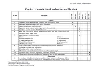
- 1. GTU Paper Analysis (New Syllabus) Kinematics of Machines (2131906) Department of Mechanical Engineering Darshan Institute of Engineering & Technology Chapter 1 – Introduction of Mechanisms and Machines Sr. No. Questions Dec- 14 Jan- 16 June- 16 Jan- 17 June- 17 Dec- 17 Theory 1. Define and discuss: kinematic link, kinematic pair, and kinematic chain. 7 3 2. Sketch and explain Whitworth quick return mechanism. 7 3. Explain Limitations of Grubler’s Criteria 3 4. Explain the terms: 1. Lower pair 2. Higher pair 3. Kinematic link 3 5. Sketch and describe four bar chain mechanism. 4 6. What are quick return motion mechanisms? Where are they used? Discuss the functioning of any one of them. 7 7. Match the items in columns I and II Column I Column II P. Higher Kinematic Pair 1. Grubler’s Equation Q. Lower Kinematic Pair 2. Line contact R. Quick Return Mechanism 3. Surface contact S. Mobility of a Linkage 4. Shaper 4 8. Draw a neat sketch of following mechanism with proper notation of the links. 1. Four bar crank and lever mechanism. 2. Four bar rocker- rocker mechanism. 4 9. Differentiate between Machine and Structure with suitable example. 4 10. Explain the term: Lower pair, Higher pair, Kinematics, Inversion. 4 11. Explain various inversion of a slider crank mechanism with the help of examples. 7 Examples 1. A crank and slotted lever mechanism used in a shaper has a centre distance of 300 mm between the centre of oscillation of the slotted lever and the centre of Rotation of the 4
- 2. GTU Paper Analysis (New Syllabus) Kinematics of Machines (2131906) Department of Mechanical Engineering Darshan Institute of Engineering & Technology crank. The radius of the cranks is 120 mm. Find the ratio of the Time of cutting to the time of return stroke 2. A crank and slotted lever mechanism used in shaper has a center distance of 300 mm between the center of oscillation of the slotted lever and the center of rotation of the crank. The radius of the crank is 120 mm. Find the ratio of the time of cutting to the time of return stroke. 7 3. A double-parallelogram mechanism is shown in the figure. Note that PQ is a single link. The mobility of the mechanism is 3 4. A simple quick return mechanism is shown in the figure. The forward to return ratio of the quick return mechanism is 2:1. If the radius of crank O1Pis 125 mm, then what will be the distance ‘d ’ (in mm) between the crank centre to lever pivot centre point ? 4
- 3. GTU Paper Analysis (New Syllabus) Kinematics of Machines (2131906) Department of Mechanical Engineering Darshan Institute of Engineering & Technology Chapter 2 – Synthesis and Analysis of Mechanisms Sr. No. Questions Dec- 14 Jan- 16 June- 16 Jan- 17 June- 17 Dec- 17 Theory 1. Explain the Freudenstein’s Equation for four bar chain mechanism. 7 2. Explain two position synthesis of four bar chain mechanism by relative pole method 7 3. Explain path generation. 4 4. Explain the Freudenstein’s method of three point synthesis of mechanisms. 7 7 5. Explain chebyshev spacing method for location precision point position in four bar chain mechanism. 7 6. Explain inversion method of synthesis for four bar mechanism using Two point and Three Point. 6 7. Explain Relative pole method of synthesis for slider crank mechanism using Two point and Three Point. 6 Examples 1. Design a four bar mechanism with input link ’a’ , coupler link ‘b’ and output link ‘c’. angles θ and Φ for three successive position are given in table below: Using Freudenstein’s Equation find out other link lengths b, c and d. assume link length a = 1. 7 2. A four bar chain mechanism is to be designed, by using three precision point to generate the function y = x1.5 for the range 1 ≤ x ≤ 4 Assuming 30° starting position and 120° finishing position for the input link and 90° 7 7
- 4. GTU Paper Analysis (New Syllabus) Kinematics of Machines (2131906) Department of Mechanical Engineering Darshan Institute of Engineering & Technology starting position and 180° finishing position for the output link, find the value of x , y , ɵ and φ corresponding to three precision point. 3. Design a four bar mechanism with input link a, output link c. Angle ɵ and φ for three successive positions are given in table. Use Freudenstein’s method. Draw the mechanism in second position. 7 4. Explain function generation, path generation and motion generation. 4
- 5. GTU Paper Analysis (New Syllabus) Kinematics of Machines (2131906) Department of Mechanical Engineering Darshan Institute of Engineering & Technology Chapter 3 – Velocity and Acceleration Analysis Sr. No. Questions Dec- 14 Jan- 16 June- 16 Jan- 17 June- 17 Dec- 17 Theory 1. Describe Klein’s construction with an example. 7 2. Derive the equation of displacement, velocity and acceleration of slider in a slider crank mechanism by analytical method 7 3. Explain Angular Velocity Theorem 4 4. Derive an expression for the magnitude and direction of Coriolis component of acceleration 7 7 5. State and prove ‘Aronhold Kennedy’s Theorem’ of three instantaneous centres. 4 6. A solid disc of radius ‘r’ rolls without slipping on a horizontal floor with angular velocity ω and angular acceleration α. Determine magnitude of the acceleration of the point of contact on the disc. 4 7. Explain the types of instantaneous centers. 3 Examples 1. The crank of a slider crank mechanism rotates clockwise at a constant speed of 300 rpm. The crank is 150 mm and connecting rod is 600 mm long. Determine 1. Linear velocity and acceleration of midpoint of connecting rod 2. Angular velocity and angular acceleration of the connecting rod, at a crank angle of 45° from inner dead centre position. 7 2. A crank and rocker mechanism ABCD has the following dimensions. AB = 0.75m, BC = 1.25m, CD = 1m, AD = 1.5m, E is the midpoint of the coupler link BC. AD is the fixed link. Crank AB has an angular velocity of 20 rad/s counter clockwise and deceleration of 280 rad/s2 at the instant angle DAB = 60° find 1. Instantaneous linear velocity and acceleration of midpoint E of link BC. 7
- 6. GTU Paper Analysis (New Syllabus) Kinematics of Machines (2131906) Department of Mechanical Engineering Darshan Institute of Engineering & Technology 2. Instantaneous angular velocity and acceleration of link CD. 3. The length of various links of a mechanism shown in Fig. are as follows: AB = DE =150 mm, BC = CD = 450 mm, EF = 375 mm The crank AB makes an angle of 45° with horizontal and rotates about A in the clockwise direction at a uniform speed of 120 rpm. The lever DC oscillates about the fixed point D, which is connected to AB by the coupler. The block F moves in the horizontal guide, being driven by the link EF. Determine 1. Velocity of the block F 2. Angular velocity of DC, and 3. Rubbing speed at the pin C which is 50 mm in diameter. 10 4. Using relative velocity method to find the absolute velocity of the slider E in the mechanism as shown in fig., when the crank rotates at 60 rpm. O1A=5cm, O2B=12cm, AB= 27cm, O2D=9cm, DE= 18cm 10
- 7. GTU Paper Analysis (New Syllabus) Kinematics of Machines (2131906) Department of Mechanical Engineering Darshan Institute of Engineering & Technology 5. A Quick return mechanism is shown in fig. Link 2 rotates at 20 rad/sec. Draw the velocity and acceleration diagram. Given BC=25 cm, OA=15 cm. 10 6. Figure shows the link mechanism of a quick return mechanism of the slotted lever type the various dimensions of which are OA= 400 mm, OP = 200 mm, AR = 700 mm, RS = 300 mm. For the configuration shown, determine the velocity of cutting tool as S and angular velocity of the link RS. The crank OP rotates at 210 rpm. 8
- 8. GTU Paper Analysis (New Syllabus) Kinematics of Machines (2131906) Department of Mechanical Engineering Darshan Institute of Engineering & Technology 7. In a slider crank mechanism, the crank is 480 mm long and rotates at 20 rad/s in the counter clockwise direction. The length of connecting rod is 1.6 m. When the crank turns 60° from the inner dead centre, determine the 1. Velocity of slider 2. Velocity of point E located at a distance 450 mm on the connecting rod extended 8 8. A crank and rocker mechanism ABCD has the following dimensions. AB=0.75 m, BC=1.25 m, CD=1 m, AD=1.5 m. E is the midpoint of the coupler link BC. AD is the fixed link. Crank AB has an angular velocity of 20 rad/s counter clockwise and deceleration of 280 rad/s2 at the instant angle DAB=60°. Find 1. Instantaneous linear velocity and acceleration of midpoint E of link BC. 2. Instantaneous angular velocity and acceleration of link CD. 14
- 9. GTU Paper Analysis (New Syllabus) Kinematics of Machines (2131906) Department of Mechanical Engineering Darshan Institute of Engineering & Technology Chapter 4 – Special Mechanisms Sr. No. Questions Dec- 14 Jan- 16 June- 16 Jan- 17 June- 17 Dec- 17 Theory 1. Derive the condition for correct steering. Sketch and show the Davis steering mechanism and discuss their advantages. 7 3 2. What is straight line motion mechanism & give its classification. Explain any one in brief. 7 3 3. Give a neat sketch of the straight line motion “Hart Mechanism”. 3 4. Derive an empirical relation for the velocity ratio of two shaft connected by Hook’s Joint. 6 7 5. Derive law of correct steering for Ackerman Steering Gear mechanism 6 6. Sketch Davis steering mechanism and discuss its advantages and disadvantages. 4 Examples 1. A double Hooke’s joint is used to connect 2 shafts in the same plane and the Intermediate shaft is inclined at an angle of 20° to both the shafts. If driving shaft Rotates of 250 rpm, find maximum and minimum speed of intermediate and driven shafts. 7 2. The hook’s joint connect two shafts whose axes are intersect. If the driving shaft rotates uniformly at 500 rpm and variation in the speed of driven shaft is not to exceed 6% of mean speed, find the maximum possible inclination between two shafts. 3 3. In a Davis steering gear, the distance between the pivots of the front axle is 1.2 meters and the wheel base is 2.7 meters. Find the inclination of the track arm to the longitudinal axis of the car, when it is moving along a straight path. 4
- 10. GTU Paper Analysis (New Syllabus) Kinematics of Machines (2131906) Department of Mechanical Engineering Darshan Institute of Engineering & Technology Chapter 5 – Gears Sr. No. Questions Dec- 14 Jan- 16 June- 16 Jan- 17 June- 17 Dec- 17 Theory 1. Derive an expression for the length of path of contact for two involutes profile gear in mesh. 7 7 2. Explain any three terminology of gear tooth with neat sketch. 3 3. What do you understand by the term “interference” as applied to the gear? 3 4 4. Explain the terms in relation to gears: (1) Module (2) Circular Pitch (3) Pressure Angle. 3 5. State and prove the “Law of gearing” 4 4 6. Comparison between Involute and Cycloidal tooth profile. 3 7. How the direction of rotation of driven shaft can be found out if it has even and odd number of gears in a gear train? Explain with sketch. 4 8. Derive the empirical relation for minimum number of teeth to avoid interference in gears. 9 9. What is contact ratio? Explain its significance. 3 10. Define: Module, Circular pitch, Diametral pitch, Addendum. 4 Examples 1. A pair 20° involute gears has module of 5 mm. the pinion has 20 teeth and gear has 60 teeth. Addendum on the pinion and gear wheel in terms of module is 1. Find the followings. (i) Number of pairs in contact (ii) Angle turned through by the pinion and gear wheel for one pair in contact. 7 2. A pinion having 30 teeth drives a gear having 80 teeth. The profile of gear is involute with 20° pressure angle, 12 mm module and 10 mm addendum. Find the contact ratio. 7 3. A pair of spur gears with involute teeth is to give a gear ratio of 4:1. The arc of approach 7
- 11. GTU Paper Analysis (New Syllabus) Kinematics of Machines (2131906) Department of Mechanical Engineering Darshan Institute of Engineering & Technology is not to be less than the circular pitch and the smaller wheel is driver. The angle of the pressure is 14.5°. Find: (1) The least number of teeth that can be used on each wheel, and (2) The addendum of the wheel in terms of the circular pitch? 4. Two 20° involute gears in mesh have a gear ratio of 2 and 20 teeth on the pinion. The module is 5mm and the pitch line speed is 1.5 m/s. Assuming addendum to be equal to one module, find (a) angle turned through by pinion when one pair of teeth are in mesh, and (b) maximum velocity of sliding. 7 5. If the number of teeth in the gears 1 and 2 are 60 and 40, the module pitch =3 mm, the pressure angle 20° and the addendum = 0.318 of circular pitch determine the velocity of sliding when the contact is at the tip of the tooth of gear 2 and the gear 2 rotates at 800 rpm. 9 6. Two gear wheels of 10 cm and 15 cm pitch diameters have involute teeth of 1.6 diametral pitch and pressure angle 20°. The addenda are 3 mm. determine: (1) Length of path of contact (2) Contact ratio (3) Angle turned by pinion, while any pair of teeth in contact. 7
- 12. GTU Paper Analysis (New Syllabus) Kinematics of Machines (2131906) Department of Mechanical Engineering Darshan Institute of Engineering & Technology Chapter 6 – Gear Trains Sr. No. Questions Dec- 14 Jan- 16 June- 16 Jan- 17 June- 17 Dec- 17 Theory 1. Enlist different type of gear train .Explain compound gear train with neat sketch .Also derive the equation of the velocity ratio for compound gear train. 7 3 2. Explain with the neat sketch the “sun and planet wheel”. 4 3. Explain with a neat sketch the “Differential Gear Box” 4 4 4. What do you understand by simple, compound, and epicyclic gear trains? 3 5. State any three application of Gear Train. 3 6. Determine the velocity ratio of differential gear box. 5 7. Explain reverted gear train with neat sketch. 4 Examples 1. An Epicyclic gear train is composed of fixed annular wheel “A” having 300 teeth. Meshing with A is wheel X which drives wheel Z through idle wheel Y, wheel Z being concentric with A. wheels X and Y are carried on an arm E which revolves clockwise at 120 rpm about the axis of A and Z. if the wheel X and Z have 50 and 80 teeth respectively .Determine the number of teeth on Y. and rpm of Y. 7 2. Figure shows an epicyclic gear train knows as Ferguson’s paradox. Gear A is fixed to the frame and is, therefore, stationary. The arm B and gears C and D are free to rotate on the shafts S. Gear A, C and D have 100, 101 and 99 teeth respectively. The planet gear has 20 teeth. The pitch circle diameters of all are the same so that the planet gear P meshes with all of them. Determine the revolutions of gears C and D for one revolution of the arm B. 7
- 13. GTU Paper Analysis (New Syllabus) Kinematics of Machines (2131906) Department of Mechanical Engineering Darshan Institute of Engineering & Technology 3. In an epiyclic gear train, an arm carries two gears A and B having 36 and 45 teeth respectively. If the arm rotates at 150 r.p.m. in the anticlockwise direction about the centre of the gear A which is fixed, Determine the speed of gear B. If the gear A instead of being fixed, makes 300 r.p.m. in the clockwise direction what will be the speed if gear B? 7 4. In a reverted epicyclic gear train, the arm F carries two wheels A and D and a compound wheel B, C. The wheel A meshes with wheel B and the wheel D meshes with wheel C. ZA=80, ZD=48 and ZC=72. Find the speed and direction of wheel D when wheel A is fixed and arm F makes 240 rpm clockwise. 7 5. Figure shows epicyclic gear train. Gear A is fixed to a frame and is therefore stationary. The arm B and gears C and D are free to rotate on the shaft. Gears A, C and D have 100,101 and 99 teeth respectively. Pitch circle diameters of all are same so that the planet gear P meshes with all of them. Determine the revolutions of gears C and D for one revolution of the arm B. 9
- 14. GTU Paper Analysis (New Syllabus) Kinematics of Machines (2131906) Department of Mechanical Engineering Darshan Institute of Engineering & Technology Chapter 7 – Cams and Followers Sr. No. Questions Dec- 14 Jan- 16 June- 16 Jan- 17 June- 17 Dec- 17 Theory 1. Classify followers and explain with neat sketch. 7 4 2. Define the following terms related to cam. (i) Base circle (ii) Pitch circle (iii) Pressure angle (iv) Stroke of the follower 4 3 4 3. Draw the displacement, Velocity and Acceleration for follower when its moves with cycloidal motion. 4 4 4. Why a roller follower is preferred to that of a knife-edged followers. 3 5. Explain with sketches the different types of cams and followers. 4 6. Draw the displacement, velocity and acceleration diagrams for a follower when it moves with (i) Uniform acceleration and retardation (ii) Cycloidal motion. 7 7. Types of Cam with sketch 4 8. State the relation for Displacement, Velocity and Acceleration for following motion of follower 1. Uniform velocity, 2. Simple harmonic motion 4 9. State the relation for Displacement, Velocity and Acceleration for following motion of follower 1. Uniform acceleration and retardation 2. Cyclodial motion 4 Examples
- 15. GTU Paper Analysis (New Syllabus) Kinematics of Machines (2131906) Department of Mechanical Engineering Darshan Institute of Engineering & Technology 1. Draw the cam operating knife edge follower from following data (i) Follower to move out through distance of 20mm during 120°. (ii) Follower to dwell for next 60°. (iii) Follower to return to its initial position during 90°. (iv) Follower to dwell for remaining cam rotation The cam rotates at 500rpm .The minimum radius of cam is 40mm and line of follower is offset 15mm from the axis of the cam and displacement to take place with uniform acceleration and retardation both inward and outward stroke . 7 2. Draw the profile of a cam rotating with an oscillating roller follower to the specification given below: 1. Follower moves outwards through an angular displacement of 200 during first 120° of cam rotation. 2. Follower returns to its original position during next 120° of cam rotation 3. Follower to dwell during the rest of cam rotation. The distance between the pivot center and roller center is 120mm, The distance between the pivot center and cam axis is 130mm , minimum radius of cam is 40mm, radius of roller is 10 mm The displacement of the follower is to take place with SHM during outward stroke and inward stroke 10 3. A cam rotating in clockwise direction at a uniform speed of 1000 rpm is required to give a roller follower the motion defined below: 1. Follower moves outwards through 50 mm during 120° of cam rotation. 2. Follower dwells for next 60° of cam rotation 3. Follower returns to its original position during next 90° of cam rotation 4. Follower dwells for rest of cam rotation The minimum radius of the cam is 50 mm and the diameter of roller is 10 mm. The line of stroke of follower is off-set by 20 mm from the axis of the cam shaft. If the displacement of the follower is to take place with uniform and equal acceleration and retardation on both the strokes. Draw the profile of the cam and find the max velocity and acceleration during the outwards and return strokes. 10 4. A cam drives a flat reciprocating follower in the following manner: During first 120° rotation of the cam, follower moves outward through a distance of 20 mm with S.H.M. The follower dwells during next 30° of cam rotation. During next 120° rotation of the cam, the follower moves inward with S.H.M. The follower dwells 7
- 16. GTU Paper Analysis (New Syllabus) Kinematics of Machines (2131906) Department of Mechanical Engineering Darshan Institute of Engineering & Technology for the next 90° of cam rotation. The minimum radius of the cam is 25 mm. Draw the profile of the cam. 5. A cam operates an offset follower. The least radius of the cam is 50mm, roller diameter is 30mm, and offset is 20mm. The cam operates at 360 rpm. The angle of ascent is 480, angle of dwell is 42° and angle of descent is 60°. The motion is SHM during ascent and uniform acceleration and retardation during descent. Draw the cam profile. Consider lift of cam as 40 mm. Also calculate max velocity and acceleration during descent. 10 6. A cam operates a flat-faced follower having uniform acceleration and retardation during ascent and descent. The least radius of the cam is 50mm. During descent, the retardation period is half of the acceleration period. The ascent lift is 37.5mm. The ascent is for 1/4th period, dwell for 1/4th , descent for 1/3th , and dwell for the remaining 1/6th period. The cam rotates at 600 rpm. Find the max velocity and acceleration during ascent and descent. Draw the cam profile. 10 7. A cam with 30 mm as minimum diameter is rotating clockwise as a uniform speed of 1200 rpm and has to give the motion to the roller follower 10 mm diameter as defined below: 1. Outward stroke of 25 mm during 120° of cam rotation with equal uniform acceleration and retardation 2. Dwell for 60° cam rotation 3. Return to its initial position during 90° of cam rotation with equal uniform acceleration and retardation 4. Dwell for the remaining 90° cam rotation Layout the cam profile when the roller axis is offset to right by 5 mm. 10 8. A cam with 25 mm as minimum diameter is rotating clockwise as a uniform speed of 500 rpm and has to give the motion to the flat faced follower defined below: 1. Outward stroke of 20 mm during 120° of cam rotation with simple harmonic motion 2. Dwell for 30° cam rotation 3. Return to its initial position during 120° of cam rotation with equal uniform acceleration and retardation 4. Dwell for the remaining 90° cam rotation 5. Layout the cam for the above mentioned motion of follower. 10 9. Draw the cam profile for a disc cam and knife edge follower from the following data 10
- 17. GTU Paper Analysis (New Syllabus) Kinematics of Machines (2131906) Department of Mechanical Engineering Darshan Institute of Engineering & Technology for one revolution of cam. (1) Angle of rise=60° (2) Follower lift=40 mm with uniform velocity (3) Angle of dwell =30° (4) Angle of fall= 60° where follower moves with uniform velocity (5) For remaining period of 210° the follower remains in same position (6) Diameter of base circle of cam= 50 mm. 10. A cam is to be designed for a knife edge follower with the following data: (1) Cam lift=40 mm during 90° of cam rotation with SHM (2) Dwell for the next 30° (3) During the next 60° of the cam rotation, the follower returns to its original position with uniform velocity. (4) Dwell during the remaining 180°. Draw the profile of the cam when the line of stroke of the follower passes through the axis of the cam shaft. The radius of the base circle of the cam is 40 mm. 10