1. 3332
VISIBILITYsteven CAsey, ergonomic systems design
iVTInternational.com September 2012iVTInternational.com September 2012
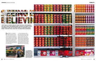
right: Chinese artist
Liu Bolin specialises in
painting himself to hide in
plain sight, such as in this
work: Hiding in the City
No. 83 - Supermarket. For
something a little more
industrial vehicle-related,
check out his confusingly
entitled Forklifts, paying
close attention to the front
wheel of the ZL50 (left)
just take a closer look at those shelves, for example.
but while most bystanders won’t be quite so hard to spot,
designing a cab For optimum visibility requires much
more than routinely meeting the required standards
“Visibility?” an industrial
vehicle operator once said to
me. “Well, it’s everything, isn’t it?”
This was his response to a question I
had asked about his requirements in
terms of visibility for a new machine
under development. We were talking
while he put his 3.5 million lb electric
mining shovel through its paces,
expertly extracting giant shovel loads
of oil sand bitumen and filling one
of the largest haul trucks in the world
in four quick passes.
He was looking down at the
‘floor’ three storeys below us, where
he precisely placed the teeth of the
shovel on the ground ahead of the
machine’s massive tracks. Then,
looking at the face of the high wall
ahead, he raised the huge bucket and
watched it fill with 70,000 lb of sticky
black soil. He then glanced over to
the haul truck below and to the side,
expertly judged its position, rotated
the machine with his joysticks and
aligned his load over the truck’s bed.
2. 34 35
VISIBILITYVISIBILITY
iVTInternational.com September 2012iVTInternational.com September 2012
own particular project, like almost
all other industrial vehicle projects,
I needed to develop a thorough
understanding of what the operator
wanted to see in order to perform
every facet of his work.
Visibility in analysis, design
and testing
Designers of an industrial vehicle –
be it a mining shovel, haul truck,
agricultural tractor, combine, motor
grader, street sweeper, or any other
of the dozens of types of vehicles
found in the sector – are always
concerned with visibility.
What must the operator see, at
least in terms of standards such as
those published by ISO? What do
operators tell us they need to see?
What can they not see that they
need to see? What does the designer
want them to see? What do they not
need to see? What are the ways in
which the designer can make things
visible or more visible? How does
one verify whether the resultant
design does indeed meet the
operator’s visibility requirements?
In addition to simply complying
with the guidelines and standards
that have been developed for most
classes of industrial vehicles, designers
need to go beyond the technical
basics and thoroughly analyse all
visibility requirements if they are to
develop purposeful and innovative
vehicles that push the state of the
art. They must analyse the tasks of
the operator, the flow of all types of
information associated with the tasks,
and the visual information needs
associated with those tasks.
Next, they must actively design
for visibility by employing various
techniques and technologies. Lastly,
they must evaluate visibility in the
new design through the use of 3D
computer modelling, old-fashioned
shadow-cast techniques and actual
evaluations with actual operators.
These three phases of system
development – analysis, design and
test/evaluation – should serve as the
framework for ensuring that the
operator’s visibility requirements are
served by the design of the vehicle.
Analysis
Filming operators while they work,
eye tracking studies and visibility
modelling in CAD are all useful
methods for studying what the
operator can see or needs to see.
Understanding the operator’s
task, and the visual requirements
associated with it, is particularly
important. Focused interviews with
operators as they work enables them
to discuss, in real time, what they
are looking at, why they are looking
at certain things and not others, and
perhaps any visual needs that are
not being met by the machine they
currently operate.
The posture of an operator in a
vehicle can often serve as a clue that
visibility is inadequate. For example,
a ‘low’ line of sight where the front
windscreen meets the roof of a cab
may cause an operator to frequently
lean forward and look up in order
to see a raised bucket, forks or load.
Similarly, an operator of a motor
grader, shovel or excavator may be
seen leaning forward to look around
the forward floor of the cab to see
the ground and implement. This may
suggest a need to improve lower lines
of sight for the cab, to improve
awkward operating postures.
The visibility requirements for
agricultural tractors are surprisingly
broad. In addition to the over-hood
requirements for operating safely on
the road, tractors must be designed
to operate with pulled implements,
pushed implements, and even other
vehicles. So, for example, can the
operator see the rear hitch in order
to link up with an implement? Is
there an unobstructed view out of
the sides and back of the cab to the
implement? Of particular importance
in many row-crop applications is
the need to see the area inside and
behind the front wheels. Wide front
consoles can sometimes hinder the
operator’s ability to see this vital
area. Visual requirements such as
these should therefore be identified
at the outset of each and every vehicle
development programme.
Visibility requirements may well
extend beyond the immediate realm
of the machine being operated. In
many environments – such as surface
mines, warehouses and construction
sites – an operator must be able to
see other vehicles and co-ordinate
activities with their operators.
Pedestrians can be expected in some
work environments and on public
roads. Vehicles of different sizes can
present special visibility problems
and safety concerns that should be
anticipated, such as small pickups
working around giant haul trucks.
Comfort is key
Driver comfort is a key factor
in machine usage, so French
cabin manufacturer Buisard is
particularly focused on this aspect
when designing new products.
Of the major comfort features
(suspension, HVAC, ergonomics,
etc.), visibility is the area in which
the company’s years of expertise
in structural design is showing the
most evidence. When developing
products for the widely different
off-highway markets, customer
needs are different, but visibility
improvement is always a must.
For instance, strong ROPS and
FOPS structures often result in the
incorporation of numerous, bulky
pillars topped with a full metal
roof. These vital safety features
are an obstacle to optimising
lateral and upper visibility.
Buisard’s development and
industrialisation teams always set
out with the aim of finding the
best compromises, and significant
improvements in visibility have
been achieved on several of its
latest cabin developments. As an
example, the recently launched
Claas Axion offers perfect visibility
together with ROPS resistance for
tractors up to 400hp and more.
In this tractor cab design, the
challenge has been to develop an
optimised four-pillar type structure
rather than the classic six-pillar
design. This has been achieved
through the right combination of
creativity, resistance calculation,
specially designed front and rear
pillars, and glass shapes that have
pushed the limits of existing
manufacturing processes.
Buisard’s innovation values
drives the 35 staff in its research
and development centre to always
deliver the required solution and
production methods for the next
project. With that forward-looking
philosophy in mind, the company
celebrated its 70th
anniversary last
year by investing in a fully robotised
welding line for high-volume cabins.
In the Sablé factory, nine latest-
generation robots now fully MAG-
weld in-line the cabin structure,
at a production rate of up to 20
cabins per shift.
www.buisard.fr
Above: The top photo shows a tractor
with a particularly wide front console;
the lower photo shows how a tapered
front console provides a clear line
of sight to the ground around the
front tyres – an especially important
consideration in row-crop applications
top: Align objects in the
visual field to reduce
masking effects
above: Orient objects in
the visual field to reduce
masking effects
Buisard developed an
optimised four-pillar design
to reduce visual obstructions
in the cab of the new Claas
Axion range
below: WIndshield height
should be determined by the
visual task, such as running
a front loader at height, and
the cab designed accordingly
Once over his target, he hit the button
on his joystick, opening the bottom
door of the bucket, and watched as
the load fell through it and the haul
truck bounced from the impact.
So, ‘visibility is everything’, I
mused. Well, almost everything, but
certainly more important than any
other sensory channel – in fact, more
important than all the other sensory
channels put together.
My thoughts drifted to a recent
image I had seen of the cockpit of
the first private spacecraft to fly into
space: SpaceShipOne. No doubt famed
aerospace designer Burt Rutan and
his associates at Scaled Composites
out in the barren Mojave Desert back
home in Southern California thought
that ‘vision was everything... or
perhaps almost everything’ when
developing their unique solution to
a visibility challenge for man’s first
private spaceship.
Faced with the need to create an
airtight pressure vessel with a shirt-
sleeve operating environment that
would withstand the vacuum of
space and the high pressures of flight
and re-entry in a lightweight vehicle,
Rutan and his team came up with a
cost-effective solution that certainly
did the job, although in a somewhat
unconventional manner (see page 37).
Indeed, visibility is almost
everything, and I knew that on my
3. VISIBILITY
37iVTInternational.com September 2012
Design
Simple cab visibility studies can be
conducted with a single representative
eye point. An often used reference
point is 150mm forward and 760mm
up from the Seat Reference Point (the
intersection of the plane of the seat
pan and the plane of the backrest).
More sophisticated visibility
studies may involve an eye ellipse,
essentially a ‘cloud’ of eye points
representing the wide population of
operators and all their anthropometric
variations in body size, sitting eye
height, seat position and posture.
The eye ellipse cloud can be
particularly useful when attempting
to determine what percentage of the
population will be accommodated
by a particular visibility design
parameter. The vehicle designer may
determine, for instance, that all but
the shortest 1% of operators could
be accommodated by a particular
line-of-sight out over an engine
hood or through a window.
The proportion of the visual field
occluded by an obstruction in the
field will reflect the object’s width
(or length) as well as its distance
from the observer. For binocular
vision using an inter-ocular distance
of 65mm, the masking effect (x) of
a component is calculated with the
following formula. Units are in
millimetres, where:
x= r ( b - 6 5 ) + 65
a
when a is the distance between
the component and the eye position,
measured along the visual radius
joining the eye position, the centre
of the component and the perimeter
of the semi-circle of vision;
b is the width, in millimetres, of
the component, which is measured
horizontally and perpendicular to
the visual radius;
r is the prescribed radius, in
millimetres, of the semi-circle of
vision (ISO 5721). In other words, r
is the distance at which the occlusion
is being assessed with the formula.
There are numerous techniques
for minimising obstructions in the
visual field of a cab. One of the
simplest is to align objects one
behind the other. An exhaust stack
on the hood of a tractor (if it can’t
be eliminated altogether) might
be aligned with a cab pillar, for
Strength under pressure
Operators of industrial vehicles
are constantly demanding greater
cabin visibility, which the OEM can
achieve by increasing the window
surface of a cabin. At the same time,
productivity requirements and
emissions regulations are making
these machines heavier.
From the cabin perspective, this
means growing demands on ROPS
weights – but increasing the ROPS
classification of a cabin usually results
in more rigid, thicker pillars, which
limit visibility. This equation is not
easy to solve.
Ruukki has solved the problem by
using Optim high-strength steels in
its cabin structures. High-strength
steels mean less material is required
for greater cabin structural strength;
this in turn enables a greater cabin
window surface than is the case when
conventional structural steels are
used. Structural optimisation starts
with an FEM analysis to simulate
cabin structure deformations and
stress under the required ROPS
weight. Various potential steel
options are simulated before the
optimum solution is chosen.
The use of high-strength steels also
reduces weight, which translates into
lower fuel consumption and emissions,
resulting in better energy efficiency.
www.ruukki.com
left: The live video
displays from the interior
‘house’, rear and sides
of a 16 million lb walking
dragline. Aids to direct
viewing, including cameras
and mirrors, should always
be considered for special
applications
left: There’s plenty of
glass in the cockpit of
SpaceShipOne
4. VISIBILITY
findings should be used as a basis for
comparison to benchmark vehicles,
a current product and the original
visibility design objectives.
Visibility maps for the final design
can be created with CAD applications,
or with traditional shadow-casting
techniques. These can be especially
useful as a sales or demonstration
aid, particularly when such maps
demonstrate a major improvement
in visibility with a new product.
Because humans are once again
the ultimate focus of all visibility
design activities, they should be part
of the test and evaluation effort too.
Actual operators should have the
opportunity to assess and critique
visibility, pointing out any necessary
final improvements to the design. If
the vehicle is to be operated at night
(which is most often the case), then
illumination and lighting must also
be part of visibility testing.
Finally, it is easy to forget about
testing visibility and illumination
for activities not directly associated
with sitting in a cab and operating
the machine. Examples include the
visibility needed for safe cab ingress
and egress, as well as common
maintenance activities. iVT
38 iVTInternational.com September 2012
example, thereby reducing by half the
obstruction created by the two objects
if they are not aligned.
The orientation of objects relative to
the operator’s line of sight can often be
modified to reduce masking effects in
the visual field. Wide columns or posts
can often be turned sideways to reduce
their visual restriction, yet still retain
sufficient structural strength. Large-
diameter round posts (or large square
posts) might be reshaped to lessen their
visual impact but retain the necessary
strength. Giving careful attention to
object alignment and orientation can
have a significant impact and make
an otherwise visually ‘busy’ cab look
surprisingly tidy.
Direct viewing by the operator of
some areas in and around an industrial
vehicle is not always possible. Visibility
design studies should therefore include
the use and effectiveness of mirrors as
well as remote cameras and in-cab video
displays. Back-up cameras on vehicles
are a good example of this application.
Visibility design activities must also
consider the operator’s need to block
direct sunlight which, in addition to
hindering vision, can create glare on
screens and displays. The presence of
improvised sun screens may point the
way to a desirable feature of a new cab.
Testing
Testing, or test and evaluation, is the
third phase of systems development,
and visibility assessments should be a
part of these activities as well. Test
HOW TO IMPROVE VISIBILITY WITHOUT CHANGING THE CAB
There are numerous ways to
improve visibility for the operator
without a full-blown redesign calling
for major structural changes to the
cab and the machine. Dozens of
technologies – ranging from the
simple to the complex – are readily
available and can be added on to a
vehicle or integrated into the overall
system at the time of manufacture.
But as with a broader cab overhaul,
it is still necessary to understand what
it is that the operator needs to see
and why, when it needs to be seen,
and what he needs to do in response
to the information that is presented.
At the simplest level, small
windows can be surprisingly effective
in providing the operator with an
occasional but desirable view. For
example, a tall narrow window in
a door enables a person inside an
elevated cab to see out and down,
perhaps down a connected platform
or stairway outside. Small windows
to the side or to the rear of a cab,
overhead, or even along the floor,
can provide direct visual access to
vehicle components, other vehicles
and structures, or even pedestrians.
Mirrors of all shapes and sizes can
be positioned to enable an operator
to see down passageways, around
corners, or the view to the rear. They
are inexpensive, reliable, and easy
to maintain – as long as access for
cleaning and maintenance has been
considered in their placement.
The price and dimensions of
video cameras and related hardware
have continued to shrink over recent
years – even while image quality
and overall system reliability has
skyrocketed. Wired and wireless
systems are being used for a wide
variety of purposes. Views that are
otherwise very difficult – if not
impossible – for an operator to
see directly can be obtained and
displayed in real time. Several
different views can be presented
simultaneously on a single monitor
when space is tight in a small cab,
or on separate monitors in a larger
cab with plenty of room. Remote
views can enhance safety, assist with
vehicle movement and also provide
essential feedback for positioning
the vehicle, load, or implement.
There may even be a need for the
operator to have control over the
direction of the view, zooming in
and out for a narrower or wider
field-of-view.
At the far end of the technology
scale are systems possessing some
form of image or sensor processing
with the purpose of sorting out or
emphasising certain elements
within the scene. Image processing
can be combined with warnings,
alarms, or other forms of feedback
for the operator.
For example, Honda’s Intelligent
Night Vision System for automobiles
relies not only on two far-infrared
cameras in the forward field of view,
but also on considerable computer
processing of the images with the
intent of aiding the driver. The
software is able to not only identify
and highlight any pedestrians in the
field of view, but also to determine
their path of motion relative to the
path of motion of the driver’s car,
and alert the driver to an impending
collision at night.
left: Semi-circle of
vision from a machine
showing typical
obscurations
Masking effect
Obscuration
Plane parallel to
the longitudinal
median plane of
the tractor
Semi-circle of
the rear
Limiting
diameter
Eye position
ABOVE AND TOP:
Spillard’s Optronics 360
surround-view system
uses multiple ultra-
wide angle cameras
mounted in strategic
locations around the
vehicle to synthesise
a quadraspheric bird’s
eye image of the
surroundings
n Blind spots
n Quadraspherical
view camera 1
n Camera 2
n Camera 3
n Camera 4
Grid (1m squares)