Expert system of single magnetic lens using JESS in Focused Ion Beam
MOPG70_160830
1. DEVELOPMENT AND COMMISSIONING OF THE NEXT GENERATION
X-RAY BEAM SIZE MONITOR IN CESR *
N.T. Rider, S.T. Barrett, M.G. Billing, J.V.Conway, B. Heltsley, A. Mikhailichenko, D.P.
Peterson, D. Rubin, J.P. Shanks, S. Wang, CLASSE, Cornell University, Ithaca, NY 14853,
U.S.A
Abstract
The CESR Test Accelerator (CESRTA) program targets
the study of beam physics issues relevant to linear collider
damping rings and other low emittance storage rings.
This endeavour requires new instrumentation to study the
beam dynamics along trains of ultra-low emittance
bunches. A key element of the program has been the
design, commissioning and operation of an x-ray beam
size monitor capable, on a turn by turn basis, of collecting
single pass measurements of each individual bunch in a
train over many thousands of turns. The x-ray beam size
monitor development has matured to include the design of
a new instrument which has been permanently integrated
into the storage ring. A new beamline has been designed
and constructed which allows for the extraction of x-rays
from the positron beam using a newly developed electro
magnet pair. This new instrument utilizes custom, high
bandwidth amplifiers and digitization hardware and
firmware to collect signals from a linear InGaAs diode
array. This paper reports on the development of this new
instrument and its integration into storage ring operation
including vacuum component design, electromagnet de-
sign, electronics and capabilities.
INTRODUCTION
The Cornell Electron Storage Ring (CESR) provides
electron and positron beams which are used for accelera-
tor research and as a synchrotron light source. Both of
these applications require diagnostic equipment and in-
strumentation to maintain particle beam and x-ray quality.
The Next Generation x-Ray Beam Size Monitor
(NGXBSM) is part of a suite of instrumentation devel-
oped for this purpose. The NGXBSM is a natural evolu-
tion of the instrument which was developed during the
early stages of the CESRTA program. This instrument
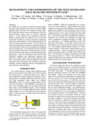
images x-rays from a bending magnet through a pinhole
optical element on to a 32x1 pixel linear array detector.
Figure 1 shows the basic concept of beam size measure-
ment using x-rays.
Fig 1: XBSM Concept
The development program has thus far leveraged the
existing beam line and support structure of the experi-
mental hutches at the Cornell High Energy Synchrotron
Source (CHESS). While this arrangement was conven-
ient, it was also temporary. The instrument was disas-
sembled at the end of every CESRTA run and reinstalled,
aligned and calibrated at the beginning of the next run.
This prevented the use of the instrument during normal
CHESS operations and limited development opportuni-
ties. The instrument provides valuable beam tuning in-
formation and an effort was undertaken to design and
build a permanently installed instrument in CESR. The
new instrument is a simplified application of the first
generation technology. It provides vertical beam size
measurements on a bunch by bunch and turn by turn ba-
sis. The available optical elements include a 35 micron
vertical pinhole, a 200 micron vertical pinhole and an
unlimited opening. These were chosen to support the
typical operating energies of CESR, 2.085 GeV and 5.3
GeV. The instrument is capable of operating with CESR
beam energies down to 1.8 GeV. First generation data
acquisition electronics and software have been utilized to
capture and process the x-ray images.
ACCELERATOR INTEGRATION
In order to reduce the risk to the accelerator vacuum
system, it was decided to pursue a windowed beam line
design with the optical elements and detector outside of
the CESR beam pipe. A beryllium window provides
physical separation between the CESR and NGXBSM
beam pipes. Usable x-ray intensity across the energy
range of the accelerator is maintained by utilizing multi-
ple x-ray sources. At 5.3 GeV an existing hard bend mag-
net is used as the x-ray source. At 2.085 GeV, a new two
pole source magnet has been designed and constructed to
provide the x-ray source. This new magnet is required to
provide sufficient x-ray flux through the beryllium win-
dow at lower CESR beam energies. The spatial require-
ments of the new beam line coupled with the requirement
for the installation of a new source magnet, limited poten-
tial instrument locations in the CESR tunnel. The loca-
tion chosen for this new instrument forced an overall
reduction in length of the x-ray path fromsource to detec-
tor when compared to the first generation instrument.
Since the instrument is effectively a pinhole camera, this
serves to reduce the effective magnification from source
to detector. In order to offset this effect, the detector has
been tilted at a 60 degree angle to functionally reduce the
pixel height and increase resolution. The present configu-
ration has a distance from source to optic of 4.4m or
6.76m, depending on which source is used, and a distance
from optic to detector of 4.4m. Motorized stages are used
to allow for precision alignment of the optical elements
Bending Magnet
Detector
Particle Beam
X-rays
Pinhole
______________________________________________________________________________________________________________________
*Work supportedby NSF grant PHY-0734867 and DOE grant DE-
FC02-08ER41538
2. and the detector. Figure 2 shows a functional overview of
the instrument and key CESR components.
Fig 2: NGXBSM Functional Diagram
VACUUM COMPONENTS
In order to transfer the x-rays from CESR to the detec-
tor, a flared vacuum chamber, beam line crotch, beryllium
window and dedicated beam line have been designed and
installed in CESR.
The flared vacuum chamber is installed inside of a
standard CESR hard bend magnet and has a large flange
which mates with the beam line crotch.
The beam line crotch is a water cooled copper device
which absorbs the fan of synchrotron radiation while
allowing the particle beam and the x-rays to pass down
their respective lines. The shape of the crotch was care-
fully designed to absorb the synchrotron radiation energy
across all operating parameters for CESR. The beryllium
window is 200 microns thick, 38 mm in diameter and
allows for the x-rays to pass from CESR vacuum into the
NGXBSM beam line. The NGXBSM beam line is rough
pumped and backfilled with helium. This provides a
clean medium so as to minimize x-ray scatter and con-
tamination. The window provides vacuum isolation as
well as filters out high energy x-rays. All vacuum com-
ponents are cooled with 85 degree Fahrenheit water
which is sourced from the main CESR cooling loop.
Figure 3 shows these new components as installed.
Fig 3: NGXBSM Vacuum Components
LOW ENERGY SOURCE MAGNET
An electro magnet pair has been designed and con-
structed to support operation at low energy. This pair, in
conjunction with an additional CESR magnet, provides
the horizontal beam trajectory necessary to generate x-
rays which are of useful energy and direction. This tra-
jectory requires a minimum of three poles to close the
horizontal orbit bump which is created at the source point.
The new magnet was limited to two poles due to spatial
constraints. An additional trim winding, which is part of
a normal CESR bending magnet, is used to close the
beam orbit disturbance created by the NGXBSM source
magnet. Maximum horizontal beam orbit displacement
within the source magnet is calculated to be 5.2 mm radi-
ally outward.
The two magnet poles are powered by a common 60
Volt, 300 Amp switched power supply. The current pro-
vided by the supply is controlled via the CESR control
system. This allows for a design field of 4.5 kG in the
shorter pole and 1.5 kG in the longer pole. The ratio
between these two magnet poles provides the proper
CESR beam trajectory for x-ray transmission. A 25 Amp
active shunt is connected around the long pole and allows
for precision adjustment of this ratio. The x-ray source
point is provided by the short pole. Figure 4 shows the
magnet as installed.
Q47 Q47AW Q48S47
BPM
Buttons
Crotch
Quad
Sextapole
Quad Quad
HB47AW SB48
BPM
Buttons
xBSM
Source
Magnet
Be
Window
xBSM
Pinhole
Optic
xBSM
Detector
Box
New Vacuum Section
Straight #1
New Vacuum Section Flared
xBSM Beam Line
DipoleDipole BPM
Buttons
CESR
WEST
CESR
EAST
New Vacuum Section Straight #2
HB46W
Dipole
5.3 GeV Source
Low Energy Source
Crotch
NGXBSM Beam Line & Be Window
CESR Beam Line
Long Pole
Short Pole
3. Fig 4: NGXBSM Source Magnet
The design magnetic field characteristics for the new
source magnet are shown in Figure 5.
Fig 5: Magnetic Field Map Of NGBSM Magnet
X-RAY SPECTRUM
The NGXBSM utilizes the same detector as the origi-
nal instrument. This detector was used in conjunction
with an existing hard bend magnet in CESR. The detector
response has been extensively studied over the course of
the CESRTA program. Figure 6 shows the inferred detec-
tor response as well as the transmission characteristics of
the 200 micron beryllium window. The detector response
was determined empirically by using a variety of filters
with a constant x-ray source.
Fig 6: Detector Response and Be Window Transmis-
sion
The new source magnet has a calculated output spec-
trum as shown in Figure 7. Here, intensity is defined to
be electromagnetic energy per unit time per unit area
perpendicular to the x-ray beam while operating at a
CESR beam energy of 2.085 GeV.
Fig 7: 2.085 GeV x-Ray Spectrum
For CESR operations at 5.3 GeV, the existing bend
magnet has a calculated output spectrum as shown in
Figure 8. A 1.5 mm aluminium filter is required to lower
the intensity so as to not saturate the detector. This filter
is removable for operation at lower CESR beam energies.
Fig 7: 5.3 GeV x-Ray Spectrum
ACCELERATOR OPTICS
In order to create enough physical space in CESR for
the installation of the new source magnet, several quad-
rupole magnets were moved. These changes coupled
with the effect of the two pole source magnet at 2.085
GeV forced a redesign of the CESR magnetic optics.
The trim winding of the closest CESR bending magnet is
used to close the horizontal bump which is introduced by
the two pole source magnet. After correction we are left
with a RMS orbit ripple of 111 microns and an RMS
horizontal dispersion ripple of 1.9 mm. This results in
an increase in horizontal emittance of 1.5%. This in-
crease is deemed acceptable.
At 5.3 GeV the existing hard bend magnet is used
with no impact on beam characteristics for CHESS opera-
tions.
MEASUREMENTS
At this point in the project, x-rays have been delivered
to the detector at both 2.085 GeV and 5.3 GeV. The pin-
hole optical elements have been manufactured but have
not yet been used to image the beam. During alignment,
a digital camera was used to capture the x-ray beamposi-
tion on the aluminium flag. Figure 9 shows the x-ray
fluorescence on the aluminium filter at 5.3 GeV.
4. Fig 9: x-ray Fluorescence At 5.3 GeV
Once basic alignment was achieved, the detector and
accompanying electronics were used to capture an x-ray
profile of the straight through beam. Careful timing cali-
brations were performed to align the sampling electronics
with the revolving bunch in CESR. This calibration posi-
tions the sampling point on the peak of the induced sig-
nals produced by each diode segment. Typical alignment
procedures produce temporal alignment within 50 pico
seconds. Figure 10 shows the detector response of
straight through beamat 2.085 GeV.
Fig 10: Straight Through Beam Image At 2.085 GeV
FUTURE EFFORTS
The motorized pinhole stage has been completed and
will be installed prior to the CESR accelerator start up in
October 2016. It is expected that alignment will be com-
pleted and measurements at 5.3 GeV will be made using
the 35 and 200 micron pinhole optics. Figure 11 shows
the pinhole stage prior to installation.
Fig 11: NGXBSM Pinhole Stage
The instrument will then be used for experimental
measurements as part of normal CHESS operations.
2.085 GeV alignment and measurements will be made
during the December 2016 CESRTA run. Additional
efforts to improve the quality of the detector itself are
being planned.
CONCLUSION
The transition of the xBSM instrument from temporary
prototype to permanently installed instrument has re-
quired significant intellectual and physical investment.
New hardware, software and operating procedures have
been developed and are presently being tested. It is ex-
pected that the instrument will be commissioned and
placed into regular operation by the end of 2016.
ACKNOWLEDGMENT
The NGXBSM development team would like to thank
the staff at CESR and CHESS for assisting in the devel-
opment of the NGXBSM. Without the riggers, surveyors,
technicians, operators and craftspeople this work would
not be possible.
REFERENCES
[1] J.P. Alexander et al, TH5RFP026, PAC09
[2] J.P. Alexander et al, TH5RFP027, PAC09
[3] J.W. Flanagan et al, TH5RFP048, PAC09
[4] D. P. Peterson et al, MOPE090, PAC10
[5] J.W. Flanagan et al, MOPE007, PAC10
[6] N.T. Rider et al, MOP304, PAC11
[7] N.T. Rider et al, WECD01, IBIC12
[8] J.P Alexander et al, NIM,
http://dx.doi.org/10.1016/j.nima.2014.02.040
[9] J.P Alexander et al, NIM,
http://dx.doi.org/10.1016/j.nima.2014.09.012
[10] J.P Alexander et al, NIM,
http://dx.doi.org/10.1016/j.nima.2015.07.028
x-ray Fluorescence
35 micron pinhole
200 micron pinhole