
Recommended
Recommended
More Related Content
What's hot
What's hot (20)
Viewers also liked
Viewers also liked (20)
Similar to Anomalous Thrust Experimentation Proposal
Similar to Anomalous Thrust Experimentation Proposal (20)
Anomalous Thrust Experimentation Proposal
- 1. Investigation of Anomalous Thrust and Proposal for Future Experimentation By Kurt Zeller and Brian Kraft California Polytechnic State University, San Luis Obispo, CA An experiment has been performed to investigate the anomalous thrust observed from an asymmetric resonant cavity. This endeavor provided valuable insight into the components and techniques required to create a successful test article. A second phase of the experiment is proposed which will investigate the anomalous thrust using a copper frustum, solid state amplifier, and a waveguide launcher. A continuous wave of electromagnetic radiation at 200 W and 1.8 to 2.4 GHz will be produced by a solid state RF amplifier and fed to the cavity via a coax to waveguide adapter. Prior to testing, a Vector Network Analyzer (VNA) will be used to ensure this mode of resonance corresponds to a strong coupling between the source and the resonant microwave system. Computer simulations will be utilized in conjunction with a VNA to ensure the cavity will resonant at the appropriate frequency and mode. Nomenclature HDPE = High Density Polyethylene NSF = National Aeronautics and Space Administration Space Flight Forums PSD = Position Sensing Device Q = Quality Factor VNA = Vector Network Analyzer VSWR = Voltage Standing Wave Ratio I. Project Description A. Previous Experiments Five independent verifications have taken place; NASA Johnson Space Center (JSC) Eagleworks has obtained 20 mN/kW.1 Northwestern Polytechnic University (NWPU) in China has yielded 1030 mN/kW at a power of 300 W.2 Satellite Propulsion Research (SPR) Ltd. led by the EM Drive inventor, Roger Shawyer, has observed 330 N/kW at a power less than 600 W.3 Cannae LLC has also observed 950 N/kW using 10.5 W in a pill-box shaped resonant cavity.4 Martin Tajmar from Dresden University in Germany has observed 29 mN/kW.5 More recently an independent experimenter, Dave Distler, achieved 0.197 mN/kW of downward thrust on a balance beam apparatus. See Appendix A for further analysis of previous experiments. The dramatic range of results is due to inconsistencies in experimental procedure. Only two tests (NASA and Tajmar) have been performed in high vacuum. Several of these resonant cavities were constructed with different geometries, tuning, and delivery mechanisms which resulted in different qualities, modes, and levels of resonance stability. Differences in signal generation between RF amplifiers and magnetrons also produced varying results. B. Resonant Cavity The first experiment utilized a partially loaded cylindrical cavity with a variety of different dielectrics.6 By varying the thickness of the dielectrics different modes can be achieved in the cavity. Based on EM Pro simulations and VNA plots it was determined that both a TM
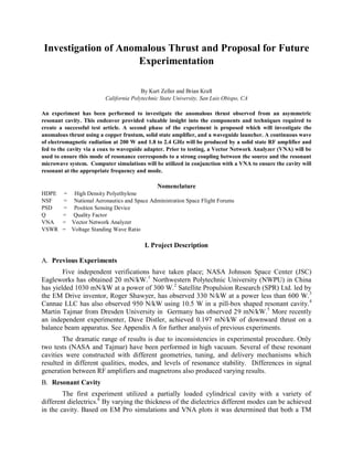
- 2. 012 and a TM 112 have been excited. This geometry was used for several reasons but most importantly for the ease of manufacturing. Furthermore, Roger Shawyer's first patent for the EM Drive featured a partially loaded cylindrical cavity with a conical dielectric therefore a cylindrical cavity seemed like a logical starting point for experimentation.7 The proposed next phase of this experiment features a copper frustum designed using the electromagnetic simulation tool EMPro. This program provides a plethora of tools commonly used in industry to design electromagnetic devices ranging from antennas to resonant cavities. It has been demonstrated that EMPro simulations can accurately predict resonant frequencies and S11 reflection plots observed with the VNA. Using our current results, a frustum with a base radius of 4.3 in, top radius of 1.3 in, and height of 8 in will be used to excite a TE011 mode at 1.96 GHz. The TE011 mode has been chosen because it is known for providing a relatively high quality.2 Fig. 1 shows a snapshot of the advanced visualization tool in EMPro used to determine the resonant modes that are present. A video of this simulation is available online.8 The frustum will be made out of a 0.048 inch thick copper plate and molded to the correct dimensions. The two endplates will be fixed together and vertical appendages will be constructed so that the position of the coax to waveguide adapter is fixed relative to the plates. Figure 1. Picture of EM Pro Simulation with Proposed Frustum Dimensions8 The Waveguide launcher as well as the coax to waveguide adapter will both be made of WR430 rectangular waveguide tubing. This tubing features a height of 2.6 in and a width of 1.7 in. The length of tubing is determined to ensure resonance at the frequency of our choosing. The
- 3. placement of the waveguide launcher relative to the frustum has been determined for maximum power transfer and quality factor. The large side of the waveguide cross section is placed vertically to allow a TE011 mode to propagate in the waveguide launcher. Exciting this mode causes the electric fields to wrap around the interior of the truncated cone upon entrance. This phenomenon will effectively "launch" the TE011 mode in the frustum. C. Pendulum System and Thrust Measurement Square aluminum tubes were cut and welded to create the frame shown below in Fig. 2. Four wires with cable tensioners were fastened to the top of the square frame to form the suspension system for the pendulum. Metal plates were machined on either end of the cylinder for the wire connections and the wires were then adjusted until the cavity was aligned in both the x and y axis. A laser and position sensing detector (PSD) have been used to measure the deflection of the pendulum with a resolution of 15-30 micrometers. This corresponds to a force resolution on the order of 0.5 mN for a pendulum mass of 3.315 kg. Figure 2. Cylindrical Resonant Cavity Test Campaign Thrust Measurement Apparatus7 The laser reflects off a mirror at the end of the cavity onto the PSD. This light sensing device is paired with an amplifier and a voltage reading is output to an oscilloscope. The position of the laser pointer relative to center point of the PSD determines the magnitude of the voltage that is output. A pulley system was used in order to show the sensitivity of the pendulum. Weights of various sizes were placed on the pulley and the corresponding deflections were recorded. See Appendix D for more information on calibration testing of the pendulum as well as the derivation of the equation for thrust as a function of displacement. D. RF Power Delivery The first phase of the experiment utilized a microwave oven magnetron mainly due to the extremely low cost and relatively high power. Unfortunately several challenges arose due to this
- 4. source including arcing, power delivery and stability. Because a magnetron outputs a constant central frequency, the cylindrical cavity was tuned using a movable plate to resonate near the magnetron's central frequency. This resulted in several design iterations that experienced high power arcing because available manufacturing capabilities were not sufficient for creating internal movable components. Although a microwave oven magnetron was deemed appropriate for this experiment, later research and experimentation revealed that they are unsuitable for this application without further components. Each microwave system has its own associated bandwidth and frequency of operation therefore a circulator and matched load would be needed to absorb reflected power. Furthermore, magnetrons are considered a relatively "dirty" sources due to their 60 MHz bandwidth asymmetric distribution of power. Additionally, this output is unstable and can vary significantly with temperature changes and time. Many attempts have been made to alter the magnetron's circuit to create a cleaner, more stable output but results have been inconsistent. [7] A signal generator and amplifier would provide a number of advantages over a magnetron due to the nature of its output signal. A signal generators and amplifier can provide a high power, narrow bandwidth signal that can be adjusted for changes in resonance. Additionally, this system more accurately conforms to mission capabilities for small satellites. The high temperature fluctuations of the spacecraft environment and the resulting thermal expansion of the cavity requires either an adjustable source or adjustable cavity. Because satellite communications already utilize a high power amplifier, it would be advantageous to develop a low thrust propulsion system that can use the same power source. A high power amplifier in the frequency range of interest can cost tens of thousands of dollars and can be incredibly expensive to rent for even brief periods of time. After discussing with veteran Electrical Engineers on an electrical design and analysis forum (edaboard.com) an older, used amplifier from a surplus store is likely the most cost effective option. Solid state Ophir amplifiers with an operational range of 1.8 to 2.17 GHz and power output of up to 200 W can be found online for approximately $3000. Essentially, purchasing a used amplifier is approximately the same price as renting a new one for only one month. Unlike the amplifier, a signal generator is more readily obtainable and could be borrowed from the electrical engineering or physics department on campus. A waveguide delivery and aperture tuning mechanism has been designed using techniques from NWPU which improved the quality above 20,000 and S11 reflection to -40 dB. This system requires a waveguide-to-coax adapter to inject the power from the amplifier into the resonant cavity system. Designing and building an adapter is possible but the manufacturing tolerances and engineering challenges would be extremely difficult to overcome. Purchasing an adapter from a respected microwave engineering manufacturer would provide the best possible means for coupling the source to the frustum and would provide a relatively low VSWR. The aperture tuning mechanism could be created separately and replaced in the event of poor coupling. An isolator is also required to protect the amplifier from reflected power which can be extremely harmful to the electrical components. Please see Appendix E for quotes for the aforementioned components. E. RF Shielding When using high power RF equipment, safety must be the primary priority. Carbon microwave absorbing sheets are a cost effective method for absorbing EM radiation. According
- 5. the manufacturer, this material can absorb more than 300 W of incident power between 1 and 10 GHz. See Appendix C for the quoted capabilities of these sheets. F. Results and Lessons Learned from Phase One of Experiment Over the course of the last three months a variety of skills and experiences have been accumulated through trial and error. Attention to detail is paramount when creating a microwave transmission line because of the sensitivity of electromagnetic waves to small perturbations. Arcing within the resonant cavity was a major challenge that was caused by inconsistent electrical connection, an isolated movable plate, and a high percentage of reflected power outside the resonant bandwidth. A successful method of electrical connection was devised which used EMF conducting strips accompanied by Ox Gard, an anti-oxidant agent. Many iterations of the movable plate design were attempted and many of them produced significant deflection of the pendulum. However it is highly likely that this deflection is purely due to asymmetric current flow through one side of the cavity. See Appendix B for a full analysis of results. G. Summary This experiment proposes to investigate an anomalous electromagnetic thrust phenomenon that has been observed by multiple independent experiments. Although the physical explanation is not yet conclusive, testing this device may further our understanding of how electromagnetic waves interact with matter and vacuum energy. This scientific endeavor has the potential to lead to revolutionary advancements in propulsion technology. If propellantless propulsion exists at the efficiencies suggested by past experiments, it will soon replace the standard for in-space electronic propulsion. II. Equipment and Facilities Required A. Signal Generator A signal generator will be used to control the frequency input to the resonant cavity. This frequency will be varied until a resonance is reached. This piece of equipment can be borrowed from either the electrical engineering department or the physics department. B. Amplifier An amplifier will be necessary to increase the power delivered to the cavity. Due to the cost of high power amplifiers, a used amplifier will be purchased from a surplus store. An Ophir Solid State Amplifier with a gain of 200 W over a frequency range of 1.8 to 2.17 GHz is the cheapest means for producing a high power source C. Isolator An isolator is a device that absorbs any reflected power at a junction between microwave components. This device prevents reflected power from destroying electrical equipment and is necessary to protect the amplifier. D. Coax to Waveguide Adapter
- 6. A coax to waveguide adapter needs to be used to allow for the highest possible power delivery to the cavity. An off the shelf adapter has a very low voltage standing wave ratio and can provide optimal coupling between the power source and the resonant system. Additionally, an off the shelf adapter will feature tolerances that are beyond the capabilities of available equipment on campus. E. RG 402 Coaxial Cable After careful consideration of different sizes of coaxial cable the RG 402 cable was chosen. A variety of parameters were weighed for each cable and RG 402 provided the greatest balance between attenuation, power delivery, and cable thickness. The RG 402 had a smaller diameter (.141") compared to other similar cable such as the RG 142 (.195") or LMR 400 (.405"). This is advantageous because the cable needs to be as flexible as possible to allow movement of the pendulum. Additionally RG 142 has an attenuation of about 22 dB per 100 feet while RG 402 has about 17 dB per 100 feet at 2 GHz. Both RG 142 and RG 402 can carry approximately the same amount of power but the previously stated advantages of RG 402 make it the logical solution. F. Coaxial Cable Connectors (SMA) The output of the Ophir Amplifier is an SMA connection therefore this connection will be used throughout the experiment. This type of connector can handle frequencies of up to 18 GHz, well above our operating frequency of 2 GHz. Furthermore it is one of the most common connections used in microwave engineering therefore a grounding plate was easy to find for the vacuum chamber. G. Facilities Required The Aero Hanger will continue to be used to manufacture different components needed to build and test our resonant cavity. Additionally, the vacuum chamber in the Spacecraft Environments Lab will be used to perform low pressure tests to eliminate the impact of thermal effects on measurements. Access to the Microwave Engineering Lab will also be necessary to utilize the Vector Network Analyzers. The Optics laboratory has been deemed appropriate for the calibration and testing phase of the experiment. The vibrationally isolated tables located in this room are ideal for low noise pendulum testing. VII. Final Products and Dissemination Once the experiment is finished the data will be analyzed and formed into a single scientific article for review. This article will outline the different theories that were tested and how these results compared to expected outcomes. Considering the scarcity of information on this topic this is most likely the greatest product of the experiment. Additionally, any information that is published about frequencies and powers used will provide valuable data points for numerical modeling that is being conducted by Dr. White of the NASA Eagleworks Team. After completion Cal Poly will also be in possession of multiple resonant cavities and a working test rig. During the summer of 2016 the abstract from the article will be submitted to the AIAA Science and Technology Forum and Exposition committee to be featured in the 2017 event.
- 7. VIII. Budget Justification The budget requested in the previous proposal was contingent upon the success of the cylindrical resonant cavity. Given the difficulties and engineering challenges that plagued this earlier prototype, the decision was made not to spend the majority of the money that was granted by CP Connect. Preliminary research and analysis has led to a much better understanding of the components and techniques required to appropriately replicate previous experiments. Purchasing an amplifier would allow many design iterations over the coming years. In addition to an amplifier, different waveguide components have been proposed to boost the quality of the resonant system and minimize reflection. Although nearly all pieces could be manufactured at Cal Poly, professionally made components such as the waveguide-to-coax and the isolator have been requested to provide the highest chance of success. IX. Acknowledgements K. Zeller and B. Kraft would like to thank their advisor, Dr. Echols, for his unyielding support. His encouragement greatly enhanced their dedication to this endeavor. They would also like to thank the participants on the NASA Space Forum as well as the various manufacturers who have provided great insight into all facets of the previous experiments as well as this particular campaign. X. References 1 Brady, D. A, White H. G, March P., Lawrence J.T., and Davies F. J., "Anomalous Thrust Production from an RF Test Device Measured on a Low-Thrust Torsion Pendulum", NASA Lyndon B. Johnson Space Center, Houston, Texas 77058, July 2014 2 Juan Y., Yu-Quan W., Yan-Jie M., Peng-Fei L., Le Y., Yang W., and Guo-Qiang H., "Prediction and experimental measurement of the electromagnetic thrust generated by a microwave thruster system", College of Astronautics, Northwestern Polytechnic University, Xi’an 710072, China, Dec 2012 3 Shawyer R., "The EM Drive-A New Satellite Propulsion Technology", SPR. Ltd., UK 4 Fetta G., "Numerical and Experimental Results for a Novel Propulsion Technology Requiring no On-Board Propellant", Cannae LLC., Doylestown PA, 18901, July 2014 5 Tajmar, M., Fiedler, G., "Direct Thrust Measurements of an EM Drive and an Evaluation of Possible Side-Effects", Institute of Aerospace Engineering, Technische Universität Dresden, 01062 Dresden, Germany 6 Shawyer, Roger. 'Electrical Propulsion Unit For Spacecraft'. 19887 NWPU 2014 7 Zeller, K., Kraft, B., "Investigation of Anomalous Thrust from a Partially Loaded Resonant Cavity", California Polytechnic State University, San Luis Obispo, 93408, Oct 2015 8 Zeller, Kurt W. "Coax to Waveguide to Frustum Resonator with Aperture Coupling." YouTube. YouTube, 9 Sept. 2015. Web. 05 Oct. 2015. VII. Appendices A: Investigation and Analysis of Anomalous Electromagnetic Propulsion Devices B: Equipment Rental Quotes