
Recommended
More Related Content
What's hot
What's hot (20)
Viewers also liked
Similar to RFID Bot
Similar to RFID Bot (20)
Recently uploaded
Recently uploaded (20)
RFID Bot
- 2. OBJECTIVE A land robot using an Arduino Micro Board was made. The robot could be controlled using any Android Phone via Bluetooth. The controls could be sent to the robot by either pressing buttons on the touch screen of the phone or by tilting the phone in various directions which changes the accelerometer values that correspond to specific control commands. The robot could also carry out station detection by using the method of Radio Frequency Identification.
- 3. COMPONENTS REQUIRED Corrugated Plastic boards [4] Wheels [2] DC Motors [2] Motor Mounting Brackets [2] Arduino Micro board [1] Motor Driver (TB6612FNG) [1] Bluetooth Module HC-05 (FC-114) [1] Castor Ball [1] Jumper Cables and Header Pins AAA Batteries with cases [6] Bread Board [1] RFID Reader (ID-20) together with SEN-13030 breakout board [1] Android Phone [1] Soldering Iron Glue, Velcro straps, Wire stripper, Pen knife
- 4. RFID (radio-frequency identification) is the wireless non-contact use of radio-frequency electromagnetic fields, for the purposes of identifying and tracking tags attached to objects. The Micro is a microcontroller board based on the ATmega32U4, developed in conjunction with Adafruit. It has 20 digital input/output pins (of which 7 can be used as PWM outputs and 12 as analog inputs), a 16 MHz crystal oscillator, a micro USB connection, an ICSP header, and a reset button. It contains everything needed to support the microcontroller; simply connect it to a computer with a micro USB cable to get started. It has a form factor that enables it to be easily placed on a breadboard. The TB6612FNG motor driver can control up to two DC motors at a constant current of 1.2A (3.2A peak). Two input signals (IN1 and IN2) can be used to control the motor in one of four function modes - CW, CCW, short-brake, and stop. The two motor outputs (A and B) can be separately controlled, the speed of each motor is controlled via a PWM input signal with a frequency up to
- 5. CHASSIS The shape of the bot was cut from the large piece of corrugated plastic board. From the same corrugated plastic board, the shape of the bot was cut out again, but with different alignment of stripes. Ample amount of superglue between the layers was applied to permanently combine them. The Castor Ball that was prepared earlier was positioned at the middle of the top and secured using superglue and screws. Motor mounts to secure the motors on each side were attached to the base using a mixture of
- 6. CIRCUIT CONNECTIONS THE ARDUINO MICRO BOARD, MOTOR CONTROL BOARD AND BLUETOOTH MODULE WERE CONNECTED TO THE TWO MOTORS AND
- 7. RFID MODULE • THE 5V PIN AND THE RST PIN WERE CONNECTED TO 5V POWER SUPPLY FROM ARDUINO BOARD. • THE FS PIN AND GND PIN WERE CONNECTED TO GROUND RAIL. • THE D0 PIN WAS CONNCETED TO RX PIN OF ARDUINO. • THIS RFID MODULE WAS PLACED IN A GROOVE CUT ON THE CHASIS FOR DETECTION OF RFID TAGS ALONG THE
- 8. ASSEMBLING ALL THE COMPONENTS Corrugated plastic Motor bracket DC Motor Wheel Castor Ball Batteries Bread board Wires Motor Control Module Bluetooth Module Arduino Micro RFID Module
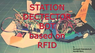
- 9. FINAL LOOK
- 13. THANK YOU