
Recommended
More Related Content
What's hot
What's hot (19)
Similar to MODIFIED TWIST ROTATION EQUATION
Similar to MODIFIED TWIST ROTATION EQUATION (20)
Recently uploaded
Recently uploaded (20)
MODIFIED TWIST ROTATION EQUATION
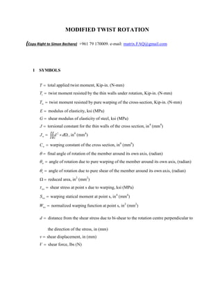
- 1. MODIFIED TWIST ROTATION (Copy Right to Simon Bechara) +961 79 170009. e-mail: matrix.FAQ@gmail.com 1 SYMBOLS T total applied twist moment, Kip-in. (N-mm) tT twist moment resisted by the thin walls under rotation, Kip-in. (N-mm) wT twist moment resisted by pure warping of the cross-section, Kip-in. (N-mm) E modulus of elasticity, ksi (MPa) G shear modulus of elasticity of steel, ksi (MPa) J torsional constant for the thin walls of the cross section, in4 (mm4 ) wJ dd 2 , in4 (mm4 ) wC warping constant of the cross section, in6 (mm6 ) final angle of rotation of the member around its own axis, (radian) w angle of rotation due to pure warping of the member around its own axis, (radian) s angle of rotation due to pure shear of the member around its own axis, (radian) reduced area, in2 (mm2 ) ws shear stress at point s due to warping, ksi (MPa) wsS warping statical moment at point s, in4 (mm4 ) wsW normalized warping function at point s, in2 (mm2 ) d distance from the shear stress due to bi-shear to the rotation centre perpendicular to the direction of the stress, in (mm) v shear displacement, in (mm) V shear force, lbs (N)
- 2. 2 VLASSOV ORIGINAL EQUATION 2.1 Review Vlassov original differential equation wtw TTECGJT Where GJTt and ww ECT 2.1 Stress Diagrams An applied twist moment, will generate lateral and longitudinal stress diagrams within the section. We will show the stresses for an I or H section as a direct application.
- 3. 2.2.1 Rotation Convention: Positive Rotation (Figure 1) 2.2.2 Thin Walls Shear Diagram: The shear stress diagram due to thin walls rotation (According to Timoshinko) : Gtt GJTt (Figure 2)
- 4. 1.2.3 Longitudinal Stress Diagram due to Warping: nsws EW ww ECT (Figure 3) 1.2.4 Shear Stress Diagram Due to Warping: dV 1w 0w dt t dVV d cs t S E ws ws ww ECT (Figure 4) ds b
- 5. 3 PRESENTATION OF THE PROBLEM 3.1 Total Twist Moment Distribution The applied twist moment T to a thin walls section will be absorbed by two different rigidities offered by the cross-section: - The rigidity of the thin walls under rotation According to Timoshinko, thin walls resist the torsion by pure shear slide rotation (Figure 1) following the equation GJTt - The rigidity of the warping ability of the cross-section The warping of a cross-section results in longitudinal stresses representing the diagram of a bending moment at each level. The twist moment resisted by the warping effect, will be the balance between the total applied twist moment and the resisted twist moment by the thin walls shear tww TTECT dVdECT ww twist moment generated by the shear forces at each location multiplied by the arm to the cs accordingly. Direct conclusion, the shear forces (stresses) resulting in wT shall generate shear displacement parallel to the shear forceV . The shear stress diagram (Figure 4) results in a shear slide movement due to the pure shear stresses that is not taken into consideration by the original equation of Vlassov. The final twist rotation , shall include the bi-shear twist rotation due to Shear Slide.
- 6. 4 MODIFICATION OF THE ORIGINAL EQUATION OF VLASSOV If: final angle of rotation of the member around its own axis w angle of rotation due to warping of the member around its own axis, neglecting the bi-shear Effect. s angle of rotation of the member around its own axis due to the bi-shear slide (Figure 4) ws s w We will start by the equilibrium equation: wt TTT The twist moment resisted by the thin wall will be wt GJT since is the final thin wall rotation ws and ws Assume the portion dtbd subject to a shear force dV (Figure 4) The area dtbd will be subject to shear displacement following the equation:
- 7. )( dtbG dV Gd dV dx dv And the generated twist moment will be dVd )( dtbG dVd Gd dVd dx dvd Knowing that sdddv )( 2 dtbG dVd Gd dVd dx dd s )( 22 dtdbG dVd dGd dVd s On the other hand, sconstant along the depth of the member. Then dtdbGddGdVdT ssw 22 Let us define ddJw 2 , in4 (mm4 ) wwsww ECGJT Where: reduced area of the of the cross-section under warping, in2 (mm2 ) d distance to the rotation centre perpendicular to the direction of the stress, in (mm) cs rotation centre The Vlassov Equation: wwwwt ECGJTTT s and w are related by the equation:
- 8. The Solution of the differential equation, will result in w On the other hand: swwww GJECT w ww s GJ EC The final rotation will be: ws 4 CONCLUSION After solving the equation of Vlassov, the final rotation will be: ws Simon Torsion Theory Where: w is Resulting from Solving Vlassov Equation. wwwwt ECGJTTT s is Resulting from Solving the Equation. w ww s GJ EC Simon Bechara +961 79 170009 e-mail: matrix.FAQ@gmail.com