Beam Analysis: Shear Force and Bending Moment Diagrams
•Download as PPT, PDF•
0 likes•2 views

- Beams are structural members that support loads at various points along their length. Transverse loads on beams can be concentrated loads or distributed loads. - Applied loads create internal forces in beams, including shear forces and bending moments. Shear forces and bending moments vary along the length of the beam. - The relationship between load, shear force, and bending moment is such that the change in shear force is related to the integral of the distributed load, and the change in bending moment is related to the integral of the shear force.

Recommended
More Related Content
Similar to Beam Analysis: Shear Force and Bending Moment Diagrams
Similar to Beam Analysis: Shear Force and Bending Moment Diagrams (20)
Recently uploaded
Recently uploaded (20)
Beam Analysis: Shear Force and Bending Moment Diagrams
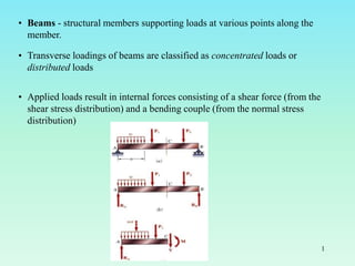
- 1. • Beams - structural members supporting loads at various points along the member. • Transverse loadings of beams are classified as concentrated loads or distributed loads • Applied loads result in internal forces consisting of a shear force (from the shear stress distribution) and a bending couple (from the normal stress distribution) 1
- 2. Classification of Beam Supports 2
- 3. ANALYSIS OF BEAM AND FRAME STRUCTURES In the case of trusses all bars were subjected to only axial loads. In beams and frames, this is not the case. Loads act everywhere therefore besides axial force, there is shear and bending moment. They are not constant. Their value change along the axis of the member. Internal force components Flexural structures V(x)=Shear M(x)=Moment N(x)=Axial a a Section at a element at a 3
- 4. F F F For Axial Force (N) Tension is positive , Compression is negative 4
- 5. For Shear Force (V) V Clockwise +ve 5
- 6. For Moment (M) concave up (sagging) +ve , hogging -ve M 6
- 7. 7
- 8. 8
- 9. 9
- 10. Positive bending moment compresses the upper part of the beam and a negative bending moment compresses the lower part of the beam. Sign conventions for stress resultants are called deformation sign conventions because they are based upon how the material is deformed. 10
- 11. Wide-flange beam supported on a concrete wall and held down by anchor bolts that pass through slotted holes in the lower flange of the beam. 11
- 12. Beam to column connection in which the beam is attached to the column flange by bolted angles. 12
- 13. Metal pole welded to a base plate that is anchored to a concrete pier embedded deep in the ground. 13
- 14. 14
- 15. 15
- 16. 16
- 17. 17
- 18. 18
- 19. 19
- 20. 20
- 21. 21
- 22. 22
- 23. 23
- 24. 24
- 25. 25
- 26. 26
- 27. 27
- 28. Relationship Between , Load, Shear and Bending Moment x x M M+M x V+V V q C Equilibrium of forces: The equilibrium of forces in the vertical direction in the segment shown of the member results in q x V V V x q V 0 ) ( q dx dV Therefore, for continuous shear loads, the change in shear is related to the integral of the distributed load. 28
- 29. Equilibrium of moments: The equilibrium of moments around the centroid C for the section shown yields ) 2 ( 2 1 0 2 ) ( 2 V V x M x V V x V M M M Taking the limit as gives 0 x V dx dM Therefore, for continuous moments, the change in moment is related to the integral of the shear load (the area under the shear diagram is related to the change in moment). 29
- 30. Slope of shear diagram at a point = intensity of distributed load at that point Slope of bending moment diagram at a point = shear at that point q dx dV V dx dM 30
- 31. 31
- 32. Load intensity 0 Constant Linear Shear force Constant Linear Parabolic B.Moment Linear Parabolic Cubic 32
- 33. 33 Problem : Construct shear force and bending moment diagrams for the given system. Show the critical values on the diagrams.
- 34. 34
- 35. 35
- 36. 36
- 37. 37 Problem : Plot shear force and bending moment diagrams for the given system. Show the critical values on the diagrams. Span length is 9 m.
- 38. 38
- 39. 39
- 40. 40
- 41. 41 Suggested Problem: Plot V and M diagrams.
- 42. 42 Suggested Problem: a-) Compute the shear force (V) value and bending moment (M) value at point C. b-) Plot V and M diagrams.
- 43. Determine the shear and moment in the beam shown in figure as a function of x. Suggested Problem : 43