
Recommended
More Related Content
What's hot
What's hot (20)
Similar to Structural Theory II (Part 2/2)
Similar to Structural Theory II (Part 2/2) (20)
More from National Chung Hsing University
More from National Chung Hsing University (11)
Recently uploaded
Recently uploaded (20)
Structural Theory II (Part 2/2)
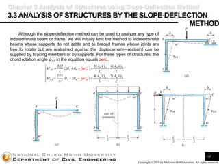
- 1. Shieh-Kung Huang Copyright © 2018 by McGraw-Hill Education. All rights reserved. 3.3ANALYSIS OF STRUCTURES BY THE SLOPE-DEFLECTION 126 Although the slope-deflection method can be used to analyze any type of indeterminate beam or frame, we will initially limit the method to indeterminate beams whose supports do not settle and to braced frames whose joints are free to rotate but are restrained against the displacement—restraint can be supplied by bracing members or by supports. For these types of structures, the chord rotation angle 𝜓NF in the equation equals zero. Chapter 3 Analysis of Structures using Slope-Deflection Method METHOD 3 2 (2 AB A B AB EI M L = + − 2 2 2( ) 4( ) 2 ( 3 ) M A M B BA A B AB A x A x L L EI M L + − = + − 2 2 4( ) 2( ) ) M A M B A x A x L L + −
- 2. Shieh-Kung Huang Copyright © 2018 by McGraw-Hill Education. All rights reserved. 3.3ANALYSIS OF STRUCTURES BY THE SLOPE-DEFLECTION 127 The basic steps of the slope-deflection method, which were discussed in last section, are summarized briefly below: 1. Identify all unknown joint displacements (rotations) to establish the number of unknowns. 2. Use the slope-deflection equation to express all member end moments in terms of joint rotations and the applied loads. 3. At each joint, except fixed supports, write the moment equilibrium equation, which states that the sum of the moments (applied by the members framing into the joint) equals zero. An equilibrium equation at a fixed support, which reduces to the identity 0 = 0, supplies no useful information. The number of equilibrium equations must equal the number of unknown displacements. As a sign convention, clockwise moments on the ends of the members are assumed to be positive. If a moment at the end of a member is unknown, it must be shown clockwise on the end of a member. The moment applied by a member to a joint is always equal and opposite in direction to the moment acting on the end of the member. If the magnitude and direction of the moment on the end of a member are known, they are shown in the actual direction. 4. Substitute the expressions for moments as a function of displacements (see step 2) into the equilibrium equations in step 3, and solve for the unknown displacements. 5. Substitute the values of displacement in step 4 into the expressions for member end moment in step 2 to establish the value of the member end moments. Once the member end moments are known, the balance of the analysis—drawing shear and moment curves or computing reactions, for example—is completed by statics. Chapter 3 Analysis of Structures using Slope-Deflection Method METHOD
- 3. Shieh-Kung Huang Copyright © 2018 by McGraw-Hill Education. All rights reserved. 3.3ANALYSIS OF STRUCTURES BY THE SLOPE-DEFLECTION 128 Chapter 3 Analysis of Structures using Slope-Deflection Method METHOD
- 4. Shieh-Kung Huang Copyright © 2018 by McGraw-Hill Education. All rights reserved. 3.3ANALYSIS OF STRUCTURES BY THE SLOPE-DEFLECTION 129 Chapter 3 Analysis of Structures using Slope-Deflection Method METHOD
- 5. Shieh-Kung Huang Copyright © 2018 by McGraw-Hill Education. All rights reserved. 3.3ANALYSIS OF STRUCTURES BY THE SLOPE-DEFLECTION 130 Chapter 3 Analysis of Structures using Slope-Deflection Method METHOD In the end, please identify steps 1 to 5!!!
- 6. Shieh-Kung Huang Copyright © 2018 by McGraw-Hill Education. All rights reserved. 3.3ANALYSIS OF STRUCTURES BY THE SLOPE-DEFLECTION 131 Chapter 3 Analysis of Structures using Slope-Deflection Method METHOD
- 7. Shieh-Kung Huang Copyright © 2018 by McGraw-Hill Education. All rights reserved. 3.3ANALYSIS OF STRUCTURES BY THE SLOPE-DEFLECTION 132 Chapter 3 Analysis of Structures using Slope-Deflection Method METHOD In the end, please identify steps 1 to 5!!!
- 8. Shieh-Kung Huang Copyright © 2018 by McGraw-Hill Education. All rights reserved. 3.3ANALYSIS OF STRUCTURES BY THE SLOPE-DEFLECTION 133 Chapter 3 Analysis of Structures using Slope-Deflection Method METHOD
- 9. Shieh-Kung Huang Copyright © 2018 by McGraw-Hill Education. All rights reserved. 3.3ANALYSIS OF STRUCTURES BY THE SLOPE-DEFLECTION 134 Chapter 3 Analysis of Structures using Slope-Deflection Method METHOD In the end, please identify steps 1 to 5!!!
- 10. Shieh-Kung Huang Copyright © 2018 by McGraw-Hill Education. All rights reserved. 3.3ANALYSIS OF STRUCTURES BY THE SLOPE-DEFLECTION 135 Chapter 3 Analysis of Structures using Slope-Deflection Method METHOD
- 11. Shieh-Kung Huang Copyright © 2018 by McGraw-Hill Education. All rights reserved. 3.3ANALYSIS OF STRUCTURES BY THE SLOPE-DEFLECTION 136 Chapter 3 Analysis of Structures using Slope-Deflection Method METHOD In the end, please identify steps 1 to 5!!!
- 12. Shieh-Kung Huang Copyright © 2018 by McGraw-Hill Education. All rights reserved. 3.3ANALYSIS OF STRUCTURES BY THE SLOPE-DEFLECTION 137 Chapter 3 Analysis of Structures using Slope-Deflection Method METHOD
- 13. Shieh-Kung Huang Copyright © 2018 by McGraw-Hill Education. All rights reserved. 3.3ANALYSIS OF STRUCTURES BY THE SLOPE-DEFLECTION 138 Chapter 3 Analysis of Structures using Slope-Deflection Method METHOD In the end, please identify steps 1 to 5!!!
- 14. Shieh-Kung Huang Copyright © 2018 by McGraw-Hill Education. All rights reserved. 3.4ANAL YSISOFSTRUCTURESTHA TAREFREETOSIDESWA Y 139 Thus far we have used the slope-deflection method to analyze indeterminate beams and frames with joints that are free to rotate but which are restrained against displacement. We now extend the method to frames whose joints are also free to sidesway, that is, to displace laterally. Since we have written equations of moment in the solution of previous problems, we will only discuss the second type of equilibrium equation—the shear equation. Chapter 3 Analysis of Structures using Slope-Deflection Method h = 1 1 2 2 0 0 0 0 0 AB BA A AB BA CD DC D CD DC CD DC AB BA x M M M M M V h V h M M M M M V h V h M M M M F Q h h + = = + − = = + = = + − = = + + = = + +
- 15. Shieh-Kung Huang Copyright © 2018 by McGraw-Hill Education. All rights reserved. 3.4ANAL YSISOFSTRUCTURESTHA TAREFREETOSIDESWA Y 140 Chapter 3 Analysis of Structures using Slope-Deflection Method
- 16. Shieh-Kung Huang Copyright © 2018 by McGraw-Hill Education. All rights reserved. 3.4ANAL YSISOFSTRUCTURESTHA TAREFREETOSIDESWA Y 141 Chapter 3 Analysis of Structures using Slope-Deflection Method
- 17. Shieh-Kung Huang Copyright © 2018 by McGraw-Hill Education. All rights reserved. 3.4ANAL YSISOFSTRUCTURESTHA TAREFREETOSIDESWA Y 142 Chapter 3 Analysis of Structures using Slope-Deflection Method
- 18. Shieh-Kung Huang Copyright © 2018 by McGraw-Hill Education. All rights reserved. 3.4ANAL YSISOFSTRUCTURESTHA TAREFREETOSIDESWA Y 143 Chapter 3 Analysis of Structures using Slope-Deflection Method
- 19. Shieh-Kung Huang Copyright © 2018 by McGraw-Hill Education. All rights reserved. 3.4ANAL YSISOFSTRUCTURESTHA TAREFREETOSIDESWA Y 144 Chapter 3 Analysis of Structures using Slope-Deflection Method ? ?
- 20. Shieh-Kung Huang Copyright © 2018 by McGraw-Hill Education. All rights reserved. 3.4ANAL YSISOFSTRUCTURESTHA TAREFREETOSIDESWA Y 145 Chapter 3 Analysis of Structures using Slope-Deflection Method
- 21. Shieh-Kung Huang Copyright © 2018 by McGraw-Hill Education. All rights reserved. 3.4ANAL YSISOFSTRUCTURESTHA TAREFREETOSIDESWA Y 146 Chapter 3 Analysis of Structures using Slope-Deflection Method ?
- 22. Shieh-Kung Huang Copyright © 2018 by McGraw-Hill Education. All rights reserved. 3.4ANAL YSISOFSTRUCTURESTHA TAREFREETOSIDESWA Y 147 Chapter 3 Analysis of Structures using Slope-Deflection Method ?
- 23. Shieh-Kung Huang Copyright © 2018 by McGraw-Hill Education. All rights reserved. 3.4ANAL YSISOFSTRUCTURESTHA TAREFREETOSIDESWA Y 148 Chapter 3 Analysis of Structures using Slope-Deflection Method
- 24. Shieh-Kung Huang Copyright © 2018 by McGraw-Hill Education. All rights reserved. 3.5 KINEMATIC INDETERMINACY 149 To analyze a structure by the flexibility method, we first established the degree of indeterminacy of the structure. The degree of statical indeterminacy determines the number of compatibility equations we must write to evaluate the redundants, which are the unknowns in the compatibility equations. In the slope-deflection method, displacements—both joint rotations and translations—are the unknowns. As a basic step in this method, we must write equilibrium equations equal in number to the independent joint displacements. The number of independent joint displacements is termed the degree of kinematic indeterminacy. To determine the kinematic indeterminacy, we simply count the number of independent joint displacements that are free to occur. • Degree of statical indeterminacy: Number of redundants (compatibility equations) • Degree of kinematic indeterminacy: Number of independent joint displacements Chapter 3 Analysis of Structures using Slope-Deflection Method
- 25. Shieh-Kung Huang Copyright © 2018 by McGraw-Hill Education. All rights reserved. ANAL YSISOFSTRUCTURESUSINGMOMENTDISTRIBUTIONMETHOD Chapter Objectives 150 Students will be able to 1. Learn the moment distribution method for analyzing indeterminate beams and frames. 2. Understand how joint equilibrium is achieved by unlocking and locking joints in succession 3. Distribute moments to both ends of all members framing to the joint until all joints achieve equilibrium. 4. Learn the procedure to analyze beams and frames with sway inhibited, and then extend the procedure to sway uninhibited. 5. Extend the use of moment distribution method to beams and frames with nonprismatic members. CHAPTER 4 4.1 Development of the Moment Distribution Method 4.2 Summary of the Moment Distribution Method with No Joint Translation 4.3 Analysis of Beams by Moment Distribution 4.4 Modification of Member Stiffness 4.5 Analysis of Frames That Are Free to Sidesway 4.6 Analysis of an Unbraced Frame for General Loading 4.7 Analysis of Multistory Frames 4.8 Nonprismatic Members Chapter Outline
- 26. Shieh-Kung Huang Copyright © 2018 by McGraw-Hill Education. All rights reserved. 4.1DEVELOPMENTOFTHEMOMENTDISTRIBUTIONMETHOD Introduction of Moment Distribution Method 151 Chapter 4 Analysis of Structures using Moment Distribution Method Moment distribution, developed by Hardy Cross in the early 1930s, is a procedure for establishing the end moments in members of indeterminate beams and frames with a series of simple computations. The moment distribution—a commonly used hand method for analyzing beams and frames rapidly— is also based on the stiffness formulation. In the moment distribution method, we imagine that temporary restraints are applied to all joints of a structure that are free to rotate or to displace. We apply hypothetical clamps to prevent rotation of joints and introduce imaginary rollers to prevent lateral displacements of joints (the rollers are required only for structures that sidesway).
- 27. Shieh-Kung Huang Copyright © 2018 by McGraw-Hill Education. All rights reserved. 4.1DEVELOPMENTOFTHEMOMENTDISTRIBUTIONMETHOD Unbalanced and Distributed End Moments 152 Chapter 4 Analysis of Structures using Moment Distribution Method In the first step, we imagine that joint B is locked against rotation by a large clamp. The application of the clamp produces two fixed-end beams. • Unbalanced Moment To prevent the joint from rotating, the clamps must apply a moment to the joint that is equal and opposite to FEMBA. The moment that develops in the clamp is called the unbalanced moment (UM). If span BC were also loaded, the unbalanced moment in the clamp would equal the difference between the fixed-end moments applied by the two members framing into the joint. • Distributed End Moments If we now remove the clamp, joint B will rotate and additional moments, labeled DEMBC, COMBC, DEMBA, and COMBA, develop at the ends of members AB and BC. These moments, called the distributed end moments (DEMs), are opposite in sense to the unbalanced moment.
- 28. Shieh-Kung Huang Copyright © 2018 by McGraw-Hill Education. All rights reserved. 4.1DEVELOPMENTOFTHEMOMENTDISTRIBUTIONMETHOD Carryover Moments 153 Chapter 4 Analysis of Structures using Moment Distribution Method In all moment distribution computations, the sign convention will be the same as that used in the slope-deflection method: Rotations of the ends of members and moments applied to the ends of members are positive in the clockwise direction and negative in the counterclockwise direction. • Carryover Moments The moments produced at the A end of member AB and at the C end of member BC by the rotation of joint B are called carryover moments (COMs). In the equation, the term 4EIAB/LAB is termed the absolute flexural stiffness of the B end of member AB. It represents the moment required to produce a rotation of 1 rad at B when the far end at A is fixed. Since both the carryover moment and the distributed end moment given by above equations are functions of θB—the only variable that has a plus or minus sign—both moments have the same sense, that is, positive if θB is clockwise and negative if θB is opposite. DEM DEM COM COM 2 2 (2 ) (2 ) FEM Member and Member 2 2 ( ) FEM ( ) BC BA BA BC BC AB BC B BA B BA BC AB AB BC AB B BA CB B AB BC EI EI M M L L AB CB EI EI M M L L = = + = + =
- 29. Shieh-Kung Huang Copyright © 2018 by McGraw-Hill Education. All rights reserved. 4.1DEVELOPMENTOFTHEMOMENTDISTRIBUTIONMETHOD Carryover and Distribution Factor 154 Chapter 4 Analysis of Structures using Moment Distribution Method • Carryover Factor If we compare the value of MBC with MCB, we reach the conclusion; that is, the carryover moment equals one-half the distributed end moment. Therefore, the carryover factor equals one-half for prismatic members. It will be shown latter that this factor will not be equal to one-half for nonprismatic members. • Distribution Factor We can establish the magnitude of the distributed end moments at joint B as The ratio is called the distribution factor (DFBA) for member AB. 4 4 UM DEM DEM 4 ( ) DEM UM DF ( ) ( ) DEM DF (UM) UM where DEM DF (UM) 4 ( ) DEM UM DF ( ) ( ) AB BC BA BC B B AB BC B AB BC AB AB BA AB AB BC AB BC BA AB B BC BC BC BC AB BC BC BC AB BC AB BC EI EI E K K L L K K K K K K K K E K K K K K K = + = + = + = = + + = = = + = = + +
- 30. Shieh-Kung Huang Copyright © 2018 by McGraw-Hill Education. All rights reserved. 4.2 SUMMARY OF THE MOMENT DISTRIBUTION METHOD 155 Chapter 4 Analysis of Structures using Moment Distribution Method The basic steps of the moment distribution method, which were discussed in last section, are summarized briefly below: 1. Draw a line diagram of the structure to be analyzed. 2. At each joint that is free to rotate, compute the distribution factor for each member and record in a box on the line diagram adjacent to the joint. The sum of the distribution factors at each joint must equal 1. 3. Write down the fixed-end moments at the ends of each loaded member. As the sign convention we take clockwise moments on the ends of members as positive and counterclockwise moments as negative. 4. Compute the unbalanced moment at the first joint to be unlocked. The unbalanced moment at the first joint is the algebraic sum of the fixed end moments at the ends of all members framing into the joint. After the first joint is unlocked, the unbalanced moments at the adjacent joints will equal the algebraic sum of fixed-end moments and any carryover moments. 5. Unlock the joint and distribute the unbalanced moment to the ends of each member framing into the joint. The distributed end moments are computed by multiplying the unbalanced moment by the distribution factor of each member. The sign of the distributed end moments is opposite to the sign of the unbalanced moment. 6. Write the carryover moments at the other end of the member. The carryover moment has the same sign as the distributed end moment but is one-half as large. 7. Replace the clamp and proceed to the next joint to distribute moments there. The analysis is finished when the unbalanced moments in all clamps are either zero or close to zero. WITH NO JOINT TRANSLATION
- 31. Shieh-Kung Huang Copyright © 2018 by McGraw-Hill Education. All rights reserved. 4.3 ANALYSIS OF BEAMS BY MOMENT DISTRIBUTION 156 Chapter 4 Analysis of Structures using Moment Distribution Method To illustrate the moment distribution procedure, we will analyze the two-span continuous beam first. Since only the joint at support B is free to rotate, a complete analysis requires only a single distribution of moments at joint B. In succeeding problems we consider structures that contain multiple joints that are free to rotate.
- 32. Shieh-Kung Huang Copyright © 2018 by McGraw-Hill Education. All rights reserved. 4.3 ANALYSIS OF BEAMS BY MOMENT DISTRIBUTION 157 Chapter 4 Analysis of Structures using Moment Distribution Method
- 33. Shieh-Kung Huang Copyright © 2018 by McGraw-Hill Education. All rights reserved. 4.3 ANALYSIS OF BEAMS BY MOMENT DISTRIBUTION 158 Chapter 4 Analysis of Structures using Moment Distribution Method
- 34. Shieh-Kung Huang Copyright © 2018 by McGraw-Hill Education. All rights reserved. 4.3 ANALYSIS OF BEAMS BY MOMENT DISTRIBUTION 159 Chapter 4 Analysis of Structures using Moment Distribution Method
- 35. Shieh-Kung Huang Copyright © 2018 by McGraw-Hill Education. All rights reserved. 4.3 ANALYSIS OF BEAMS BY MOMENT DISTRIBUTION 160 Chapter 4 Analysis of Structures using Moment Distribution Method
- 36. Shieh-Kung Huang Copyright © 2018 by McGraw-Hill Education. All rights reserved. 4.3 ANALYSIS OF BEAMS BY MOMENT DISTRIBUTION 161 Chapter 4 Analysis of Structures using Moment Distribution Method
- 37. Shieh-Kung Huang Copyright © 2018 by McGraw-Hill Education. All rights reserved. 4.3 ANALYSIS OF BEAMS BY MOMENT DISTRIBUTION 162 Chapter 4 Analysis of Structures using Moment Distribution Method What if we start to distribute the moment from joint C?
- 38. Shieh-Kung Huang Copyright © 2018 by McGraw-Hill Education. All rights reserved. 4.3 ANALYSIS OF BEAMS BY MOMENT DISTRIBUTION 163 Chapter 4 Analysis of Structures using Moment Distribution Method What if we distribute the moment from both joint B and joint C?
- 39. Shieh-Kung Huang Copyright © 2018 by McGraw-Hill Education. All rights reserved. 4.3 ANALYSIS OF BEAMS BY MOMENT DISTRIBUTION 164 Chapter 4 Analysis of Structures using Moment Distribution Method
- 40. Shieh-Kung Huang Copyright © 2018 by McGraw-Hill Education. All rights reserved. 4.3 ANALYSIS OF BEAMS BY MOMENT DISTRIBUTION 165 Chapter 4 Analysis of Structures using Moment Distribution Method
- 41. Shieh-Kung Huang Copyright © 2018 by McGraw-Hill Education. All rights reserved. 4.4 MODIFICATION OF MEMBER STIFFNESS Cases of Hinges 166 Chapter 4 Analysis of Structures using Moment Distribution Method We can often reduce the number of cycles of moment distribution required to analyze a continuous structure by adjusting the flexural stiffness of certain members. In this section we consider members whose ends terminate at an exterior support consisting of either a pin or roller. To measure the influence of end conditions on the flexural stiffness of a beam, we can compare the moment required to produce a unit rotation (1 rad) of the end of a member for various end conditions. Comparing above examples, we see that a beam loaded by a moment at one end whose far end is pinned is three-fourths as stiff with respect to resistance to joint rotation as a beam of the same dimensions whose far end is fixed.
- 42. Shieh-Kung Huang Copyright © 2018 by McGraw-Hill Education. All rights reserved. 4.4 MODIFICATION OF MEMBER STIFFNESS 167 Chapter 4 Analysis of Structures using Moment Distribution Method
- 43. Shieh-Kung Huang Copyright © 2018 by McGraw-Hill Education. All rights reserved. 4.4 MODIFICATION OF MEMBER STIFFNESS 168 Chapter 4 Analysis of Structures using Moment Distribution Method
- 44. Shieh-Kung Huang Copyright © 2018 by McGraw-Hill Education. All rights reserved. 4.4 MODIFICATION OF MEMBER STIFFNESS 169 Chapter 4 Analysis of Structures using Moment Distribution Method
- 45. Shieh-Kung Huang Copyright © 2018 by McGraw-Hill Education. All rights reserved. 4.4 MODIFICATION OF MEMBER STIFFNESS 170 Chapter 4 Analysis of Structures using Moment Distribution Method
- 46. Shieh-Kung Huang Copyright © 2018 by McGraw-Hill Education. All rights reserved. 4.4 MODIFICATION OF MEMBER STIFFNESS 171 Chapter 4 Analysis of Structures using Moment Distribution Method
- 47. Shieh-Kung Huang Copyright © 2018 by McGraw-Hill Education. All rights reserved. 4.4 MODIFICATION OF MEMBER STIFFNESS 172 Chapter 4 Analysis of Structures using Moment Distribution Method
- 48. Shieh-Kung Huang Copyright © 2018 by McGraw-Hill Education. All rights reserved. 4.4 MODIFICATION OF MEMBER STIFFNESS Cases of Single and Double Curvature Bending 173 Chapter 4 Analysis of Structures using Moment Distribution Method If a member is bent into double curvature by equal end moments, the resistance to rotation increases because the moment at B, the far end, rotates the near end A in a direction opposite in sense to the moment at A. Comparing example in the last slide, we find that the absolute stiffness for a member bent in double curvature by equal end moments is 50 percent greater than the stiffness of a beam whose far end is fixed against rotation. If a flexural member is acted on by equal values of end moments, producing single-curvature bending, the effective bending stiffness with respect to the A end is reduced because the moment at the far end (the B end) contributes to the rotation at the A end. Comparing example in the last slide, we find that the absolute stiffness of a member bent into single curvature by equal end moments has an effective stiffness that is 50 percent smaller than that of a beam whose far end is fixed against rotation. 6 AB EI M L = 2 AB EI M L =
- 49. Shieh-Kung Huang Copyright © 2018 by McGraw-Hill Education. All rights reserved. 4.4 MODIFICATION OF MEMBER STIFFNESS Cases of Single and Double Curvature Bending 174 Chapter 4 Analysis of Structures using Moment Distribution Method 6EI L = 2EI L =
- 50. Shieh-Kung Huang Copyright © 2018 by McGraw-Hill Education. All rights reserved. 4.4 MODIFICATION OF MEMBER STIFFNESS Other Cases 175 Chapter 4 Analysis of Structures using Moment Distribution Method • Stiffness of a Cantilever Note that once you modified the stiffness, you don’t need to carryover the moment again (no COM).
- 51. Shieh-Kung Huang Copyright © 2018 by McGraw-Hill Education. All rights reserved. 4.4 MODIFICATION OF MEMBER STIFFNESS 176 Chapter 4 Analysis of Structures using Moment Distribution Method
- 52. Shieh-Kung Huang Copyright © 2018 by McGraw-Hill Education. All rights reserved. 4.4 MODIFICATION OF MEMBER STIFFNESS 177 Chapter 4 Analysis of Structures using Moment Distribution Method
- 53. Shieh-Kung Huang Copyright © 2018 by McGraw-Hill Education. All rights reserved. 4.4 MODIFICATION OF MEMBER STIFFNESS 178 Chapter 4 Analysis of Structures using Moment Distribution Method
- 54. Shieh-Kung Huang Copyright © 2018 by McGraw-Hill Education. All rights reserved. 4.4 MODIFICATION OF MEMBER STIFFNESS 179 Chapter 4 Analysis of Structures using Moment Distribution Method What if we just don’t use the modified stiffness? Case 1: no consideration of hinge and symmetry There is always some moment at hinge!!! 360 20 18 600 15 40 AB AB AB CD AB BC BC BC BC E I K K E E L E I K E E L = = = = = = =
- 55. Shieh-Kung Huang Copyright © 2018 by McGraw-Hill Education. All rights reserved. 4.4 MODIFICATION OF MEMBER STIFFNESS 180 Chapter 4 Analysis of Structures using Moment Distribution Method What if we just don’t use the modified stiffness? Case 2: no consideration of symmetry Still not over yet!!! 3 3 360 15 4 4 18 600 15 40 AB AB AB CD AB BC BC BC BC E I K K E E L E I K E E L = = = = = = =
- 56. Shieh-Kung Huang Copyright © 2018 by McGraw-Hill Education. All rights reserved. 4.4 MODIFICATION OF MEMBER STIFFNESS Other Cases 181 Chapter 4 Analysis of Structures using Moment Distribution Method • Support Settlements, Fabrication Errors, and Temperature Change Moment distribution and the slope-deflection equation provide an effective combination for determining the moments created in indeterminate beams and frames by fabrication errors, support settlements, and temperature change. In this application the appropriate displacements are introduced into the structure while simultaneously all joints that are free to rotate are locked by clamps against rotation in their initial orientation. Locking the joints against rotation ensures that the changes in slope at the ends of all members are zero and permits the end moments produced by specified values of displacement to be evaluated by the slope-deflection equation. To complete the analysis, the clamps are removed and the structure is allowed to deflect into its final equilibrium position. In Example 11.7 we use this procedure to determine the moments in a structure whose supports are not located in their specified position—a common situation that frequently occurs during the construction. In Example 11.8 the method is used to establish the moments created in an indeterminate frame by a fabrication error. 2 (2 3 ) FEM where NF N F NF NF I M EK K L = + − + = 2 (2 3 ) FEM 2 ( 2 3 ) FEM AB A B AB AB BA A B AB BA M EK M EK = + − + = + − + 2 2 2 2 2( ) 4( ) 2 (2 3 ) 4( ) 2( ) 2 ( 3 ) M A M B AB A B AB M A M B BA A B AB A x A x EI M L L L A x A x EI M L L L = + − + − = + − + −
- 57. Shieh-Kung Huang Copyright © 2018 by McGraw-Hill Education. All rights reserved. 4.4 MODIFICATION OF MEMBER STIFFNESS 182 Chapter 4 Analysis of Structures using Moment Distribution Method
- 58. Shieh-Kung Huang Copyright © 2018 by McGraw-Hill Education. All rights reserved. 4.4 MODIFICATION OF MEMBER STIFFNESS 183 Chapter 4 Analysis of Structures using Moment Distribution Method
- 59. Shieh-Kung Huang Copyright © 2018 by McGraw-Hill Education. All rights reserved. 4.4 MODIFICATION OF MEMBER STIFFNESS 184 Chapter 4 Analysis of Structures using Moment Distribution Method
- 60. Shieh-Kung Huang Copyright © 2018 by McGraw-Hill Education. All rights reserved. 4.4 MODIFICATION OF MEMBER STIFFNESS 185 Chapter 4 Analysis of Structures using Moment Distribution Method
- 61. Shieh-Kung Huang Copyright © 2018 by McGraw-Hill Education. All rights reserved. 4.4 MODIFICATION OF MEMBER STIFFNESS 186 Chapter 4 Analysis of Structures using Moment Distribution Method
- 62. Shieh-Kung Huang Copyright © 2018 by McGraw-Hill Education. All rights reserved. 4.5 ANALYSIS OF FRAMES THAT ARE FREE TO SIDESWAY 187 Chapter 4 Analysis of Structures using Moment Distribution Method All structures that we have analyzed thus far contained joints that were free to rotate but not translate. Frames of this type are called braced frames. When certain joints of an unbraced frame are free to translate, the designer must include the moments created by chord rotations. Typically, a unit displacement is introduced. To hold the structure in the deflected position, temporary restraints are introduced. These restraints consist of a roller at B to maintain the 1. displacement and clamps at A, B, and C to prevent joint rotation. Clamps are now removed and moments distributed until the structure relaxes into its equilibrium position. In the equilibrium position, the temporary roller at B applies a lateral force S to the frame. The force required to produce a unit displacement of the frame, denoted by S, is termed a stiffness coefficient. 2 2 6 ( 3 ) NF NF EI EI M L L = − = −
- 63. Shieh-Kung Huang Copyright © 2018 by McGraw-Hill Education. All rights reserved. 4.5 ANALYSIS OF FRAMES THAT ARE FREE TO SIDESWAY 188 Chapter 4 Analysis of Structures using Moment Distribution Method
- 64. Shieh-Kung Huang Copyright © 2018 by McGraw-Hill Education. All rights reserved. 4.5 ANALYSIS OF FRAMES THAT ARE FREE TO SIDESWAY 189 Chapter 4 Analysis of Structures using Moment Distribution Method
- 65. Shieh-Kung Huang Copyright © 2018 by McGraw-Hill Education. All rights reserved. 4.5 ANALYSIS OF FRAMES THAT ARE FREE TO SIDESWAY 190 Chapter 4 Analysis of Structures using Moment Distribution Method
- 66. Shieh-Kung Huang Copyright © 2018 by McGraw-Hill Education. All rights reserved. 4.5 ANALYSIS OF FRAMES THAT ARE FREE TO SIDESWAY 191 Chapter 4 Analysis of Structures using Moment Distribution Method
- 67. Shieh-Kung Huang Copyright © 2018 by McGraw-Hill Education. All rights reserved. 4.5 ANALYSIS OF FRAMES THAT ARE FREE TO SIDESWAY 192 Chapter 4 Analysis of Structures using Moment Distribution Method
- 68. Shieh-Kung Huang Copyright © 2018 by McGraw-Hill Education. All rights reserved. 4.6ANALYSIS OFAN UNBRACED FRAME FOR GENERAL 193 Chapter 4 Analysis of Structures using Moment Distribution Method LOADING If a structure that is loaded between joints undergoes sidesway, we begin the analysis by introducing temporary restraints (holding forces) to prevent joints from translating. The restrained structure is then analyzed by moment distribution for the loads applied between joints. After the shears in all members are computed from free bodies of individual members, the holding forces are evaluated using the equations of statics by considering the equilibrium of members and/or joints. Superposition of the Case A and Case B analyses produces results equivalent to the original case.
- 69. Shieh-Kung Huang Copyright © 2018 by McGraw-Hill Education. All rights reserved. 4.6ANALYSIS OFAN UNBRACED FRAME FOR GENERAL 194 Chapter 4 Analysis of Structures using Moment Distribution Method LOADING
- 70. Shieh-Kung Huang Copyright © 2018 by McGraw-Hill Education. All rights reserved. 4.6ANALYSIS OFAN UNBRACED FRAME FOR GENERAL 195 Chapter 4 Analysis of Structures using Moment Distribution Method LOADING
- 71. Shieh-Kung Huang Copyright © 2018 by McGraw-Hill Education. All rights reserved. 4.6ANALYSIS OFAN UNBRACED FRAME FOR GENERAL 196 Chapter 4 Analysis of Structures using Moment Distribution Method LOADING
- 72. Shieh-Kung Huang Copyright © 2018 by McGraw-Hill Education. All rights reserved. 4.6ANALYSIS OFAN UNBRACED FRAME FOR GENERAL 197 Chapter 4 Analysis of Structures using Moment Distribution Method LOADING
- 73. Shieh-Kung Huang Copyright © 2018 by McGraw-Hill Education. All rights reserved. 4.6ANALYSIS OFAN UNBRACED FRAME FOR GENERAL 198 Chapter 4 Analysis of Structures using Moment Distribution Method LOADING
- 74. Shieh-Kung Huang Copyright © 2018 by McGraw-Hill Education. All rights reserved. 4.6ANALYSIS OFAN UNBRACED FRAME FOR GENERAL 199 Chapter 4 Analysis of Structures using Moment Distribution Method LOADING
- 75. Shieh-Kung Huang Copyright © 2018 by McGraw-Hill Education. All rights reserved. 4.7 ANALYSIS OF MULTISTORY FRAMES 200 Chapter 4 Analysis of Structures using Moment Distribution Method To extend moment distribution to the analysis of multistory frames, we must add one sidesway correction for each independent degree of sidesway. Since the repeated analysis of the frame for the various cases becomes time consuming, we will only outline the method of analysis, so the student is aware of the complexity of the solution. In practice, engineers today use computer programs to analyze frames of all types.
- 76. Shieh-Kung Huang Copyright © 2018 by McGraw-Hill Education. All rights reserved. INFLUENCELINESFORSTATICALLYINDETERMINATESTRUCTURES Chapter Objectives 201 1. understand the concept of and the need for influence lines 2. learn the Müller–Breslau principle to graphically construct influence lines 3. draw the influence line for a statically indeterminate beams 4. draw the influence line for a statically indeterminate trusses CHAPTER 5 5.1 Influence Lines 5.2 Müller–Breslau Principle 5.3 Qualitative Influence Lines for Indeterminate Beams and Frames 5.4 Influence Lines for Indeterminate Trusses Chapter Outline
- 77. Shieh-Kung Huang Copyright © 2018 by McGraw-Hill Education. All rights reserved. 5.1 INFLUENCE LINES 202 Chapter 5 Influence Lines for Statically Indeterminate Structures If a structure is to be safely designed, we must proportion its members and joints so that the maximum force at each section produced by load is less than or equal to the available capacity. To establish maximum design forces at critical sections produced by moving loads, we frequently construct influence lines. An influence line is a diagram whose ordinates, which are plotted as a function of distance along the span, give the value of an internal force, a reaction, or a displacement at a particular point in a structure as a unit load of 1 kip or 1 kN moves across the structure. Once the influence line is constructed, we can use it to determine where to place live load on a structure to maximize the force (shear, moment, etc.) for which the influence line is drawn, and to evaluate the magnitude of the force (represented by the influence line) produced by the live load. Although an influence line represents the action of a single moving load, it can also be used to establish the force at a point produced by several concentrated loads or by a uniformly distributed load.
- 78. Shieh-Kung Huang Copyright © 2018 by McGraw-Hill Education. All rights reserved. 5.2 MÜ LLER–BRESLAU PRINCIPLE 203 Chapter 5 Influence Lines for Statically Indeterminate Structures The Müller–Breslau principle provides a simple procedure for establishing the shape of influence lines for the reactions or the internal forces (shear and moment) in beams. The principle states: The influence line for any reaction or internal force (shear, moment) corresponds to the deflected shape of the structure produced by removing the capacity of the structure to carry that force and then introducing into the modified (or released) structure a unit deformation that corresponds to the restraint removed.
- 79. Shieh-Kung Huang Copyright © 2018 by McGraw-Hill Education. All rights reserved. 5.2 MÜ LLER–BRESLAU PRINCIPLE 204 Chapter 5 Influence Lines for Statically Indeterminate Structures
- 80. Shieh-Kung Huang Copyright © 2018 by McGraw-Hill Education. All rights reserved. 5.3 QUALITATIVE INFLUENCE LINES FOR INDETERMINATE 205 Chapter 5 Influence Lines for Statically Indeterminate Structures In this section we illustrate the use of the Müller–Breslau method to construct qualitative influence lines for a variety of forces in continuous beams and frames. As described in the Müller–Breslau method, we first remove the capacity of the structure to carry the function represented by the influence line. At the location of the release, we introduce a displacement that corresponds to the restraint released. The resulting deflected shape is the influence line to some scale. BEAMSAND FRAMES
- 81. Shieh-Kung Huang Copyright © 2018 by McGraw-Hill Education. All rights reserved. 5.3 QUALITATIVE INFLUENCE LINES FOR INDETERMINATE 206 Chapter 5 Influence Lines for Statically Indeterminate Structures In the following examples, we use the Müller–Breslau principle to sketch qualitative influence lines for a variety of forces and reactions in a three-span continuous beam. BEAMSAND FRAMES
- 82. Shieh-Kung Huang Copyright © 2018 by McGraw-Hill Education. All rights reserved. 5.3 QUALITATIVE INFLUENCE LINES FOR INDETERMINATE 207 Chapter 5 Influence Lines for Statically Indeterminate Structures BEAMSAND FRAMES
- 83. Shieh-Kung Huang Copyright © 2018 by McGraw-Hill Education. All rights reserved. 5.3 QUALITATIVE INFLUENCE LINES FOR INDETERMINATE 208 Chapter 5 Influence Lines for Statically Indeterminate Structures BEAMSAND FRAMES
- 84. Shieh-Kung Huang Copyright © 2018 by McGraw-Hill Education. All rights reserved. 5.3 QUALITATIVE INFLUENCE LINES FOR INDETERMINATE 209 Chapter 5 Influence Lines for Statically Indeterminate Structures BEAMSAND FRAMES
- 85. Shieh-Kung Huang Copyright © 2018 by McGraw-Hill Education. All rights reserved. 5.3 QUALITATIVE INFLUENCE LINES FOR INDETERMINATE 210 Chapter 5 Influence Lines for Statically Indeterminate Structures BEAMSAND FRAMES
- 86. Shieh-Kung Huang Copyright © 2018 by McGraw-Hill Education. All rights reserved. 5.3 QUALITATIVE INFLUENCE LINES FOR INDETERMINATE 211 Chapter 5 Influence Lines for Statically Indeterminate Structures BEAMSAND FRAMES
- 87. Shieh-Kung Huang Copyright © 2018 by McGraw-Hill Education. All rights reserved. 5.3 QUALITATIVE INFLUENCE LINES FOR INDETERMINATE 212 Chapter 5 Influence Lines for Statically Indeterminate Structures BEAMSAND FRAMES
- 88. Shieh-Kung Huang Copyright © 2018 by McGraw-Hill Education. All rights reserved. 5.3 QUALITATIVE INFLUENCE LINES FOR INDETERMINATE 213 Chapter 5 Influence Lines for Statically Indeterminate Structures BEAMSAND FRAMES
- 89. Shieh-Kung Huang Copyright © 2018 by McGraw-Hill Education. All rights reserved. 5.3 QUALITATIVE INFLUENCE LINES FOR INDETERMINATE 214 Chapter 5 Influence Lines for Statically Indeterminate Structures BEAMSAND FRAMES
- 90. Shieh-Kung Huang Copyright © 2018 by McGraw-Hill Education. All rights reserved. 5.3 QUALITATIVE INFLUENCE LINES FOR INDETERMINATE 215 Chapter 5 Influence Lines for Statically Indeterminate Structures BEAMSAND FRAMES
- 91. Shieh-Kung Huang Copyright © 2018 by McGraw-Hill Education. All rights reserved. 5.3 QUALITATIVE INFLUENCE LINES FOR INDETERMINATE 216 Chapter 5 Influence Lines for Statically Indeterminate Structures BEAMSAND FRAMES
- 92. Shieh-Kung Huang Copyright © 2018 by McGraw-Hill Education. All rights reserved. 5.3 QUALITATIVE INFLUENCE LINES FOR INDETERMINATE 217 Chapter 5 Influence Lines for Statically Indeterminate Structures BEAMSAND FRAMES
- 93. Shieh-Kung Huang Copyright © 2018 by McGraw-Hill Education. All rights reserved. 5.3 QUALITATIVE INFLUENCE LINES FOR INDETERMINATE 218 Chapter 5 Influence Lines for Statically Indeterminate Structures BEAMSAND FRAMES
- 94. Shieh-Kung Huang Copyright © 2018 by McGraw-Hill Education. All rights reserved. 5.4 INFLUENCE LINES FOR INDETERMINATE TRUSSES 219 Chapter 5 Influence Lines for Statically Indeterminate Structures Using the basic definition, influence lines of a truss that is indeterminate to the first degree is presented in the following example. The flexibility method is used to analyze the truss.
- 95. Shieh-Kung Huang Copyright © 2018 by McGraw-Hill Education. All rights reserved. 5.4 INFLUENCE LINES FOR INDETERMINATE TRUSSES 220 Chapter 5 Influence Lines for Statically Indeterminate Structures
- 96. Shieh-Kung Huang Copyright © 2018 by McGraw-Hill Education. All rights reserved. 5.4 INFLUENCE LINES FOR INDETERMINATE TRUSSES 221 Chapter 5 Influence Lines for Statically Indeterminate Structures
- 97. Shieh-Kung Huang Copyright © 2018 by McGraw-Hill Education. All rights reserved. 5.4 INFLUENCE LINES FOR INDETERMINATE TRUSSES 222 Chapter 5 Influence Lines for Statically Indeterminate Structures
- 98. Shieh-Kung Huang Copyright © 2018 by McGraw-Hill Education. All rights reserved. INTRODUCTION TO THE GENERAL STIFFNESS METHOD Chapter Objectives 223 Students will be able to 1. Learn the transition from the classical to matrix methods of structural analysis 2. Understand the differences between the classical flexibility method and stiffness (slope-deflection) method 3. Extend the stiffness method to a general stiffness method for analyzing an indeterminate structure with only one degree of kinematic indeterminacy. CHAPTER 6 6.1 Comparison between Flexibility and Stiffness Methods 6.2 Analysis of an Indeterminate Structure by the General Stiffness Method Chapter Outline
- 99. Shieh-Kung Huang Copyright © 2018 by McGraw-Hill Education. All rights reserved. 6.1 COMPARISON BETWEEN FLEXIBILITYAND STIFFNESS Flexibility Method 224 Chapter 6 Introduction to the General Stiffness Method This chapter provides a transition from classical methods of hand analysis, such as the flexibility method, slope-deflection method, or moment distribution method, to analysis by computer using general stiffness method. METHODS 10 1 10 11 1 1 11 20 2 2 2 2 2 2 1 11 1 21 2 1 2 1 1 2 2 1 1 2 2 0 0 F F F L PL A E A E F F L F L L L AE A E AE A E = + = = − = − = − + + In the flexibility method, we write compatibility equations in terms of unknown redundant forces. In the stiffness method, we write equilibrium equations in terms of unknown joint displacements. • Analysis using Flexibility Method To analyze the structure, we select the horizontal reaction F1 at joint 1 as the redundant. We produce a stable determinate released structure by imagining that the pin at joint 1 is replaced by a roller. To determine the reaction F1, we write an equation of compatibility based on the geometric requirement that the horizontal displacement at support 1 must be zero.
- 100. Shieh-Kung Huang Copyright © 2018 by McGraw-Hill Education. All rights reserved. Since the restraining force exerted by the bars is a linear function of the displacement of joint 2, the actual joint displacement Δ2 can be determined by writing the equilibrium equation for forces in the horizontal direction at joint 2. The quantity K2 is called a stiffness coefficient. If the two bars are treated as a large spring, the stiffness coefficient measures the resistance (or stiffness) of the system to deformation. 6.1 COMPARISON BETWEEN FLEXIBILITYAND STIFFNESS Stiffness Method 225 Chapter 6 Introduction to the General Stiffness Method • Analysis using Stiffness Method The structure will now be reanalyzed by the stiffness method. Since only joint 2 is free to displace, the structure is kinematically indeterminate to the first degree. METHODS 1 1 1 1 1 1 2 1 1 1 2 2 2 2 2 2 2 2 2 2 2 (T) and (C) AE AE F L L L L L A E A E F L L L = = = = = = 1 1 2 2 1 2 2 2 1 2 2 1 1 2 2 2 1 2 0 0 AE A E P F F P L L P P AE A E K L L − − = − − = = = +
- 101. Shieh-Kung Huang Copyright © 2018 by McGraw-Hill Education. All rights reserved. 6.2ANALYSIS OFAN INDETERMINATE STRUCTURE BY THE 226 Chapter 6 Introduction to the General Stiffness Method The next example shows a continuous beam of constant cross section. Since the only unknown displacement of the continuous beam is the rotation θ2 that occurs at joint 2, the structure is kinematically indeterminate to the first degree. GENERAL STIFFNESS METHOD
- 102. Shieh-Kung Huang Copyright © 2018 by McGraw-Hill Education. All rights reserved. 6.2ANALYSIS OFAN INDETERMINATE STRUCTURE BY THE Summary of the General Stiffness Method 227 Chapter 6 Introduction to the General Stiffness Method The analysis of the last example is based on the superposition of two cases. − In case 1, we clamp all joints that are free to rotate and apply the load. The load creates fixed-end moments in the beam and an equal moment in the clamp. At this point the structure is in equilibrium with the load; however, the joint has been restrained by a clamp and not allowed to rotate. − To eliminate the clamp, we must remove it and allow the joint to rotate. This rotation will produce additional moments in the members. Since we do not know the magnitude of the rotation, in a separate case 2, we arbitrarily introduce a unit rotation of 1 rad and clamp the beam in the deflected position. The case 2 clamp now applies a moment, termed a stiffness coefficient, which holds the beam in the rotated position. If we now multiply the forces and displacements in case 2 by the actual magnitude of the joint rotation θ2, all forces and displacements (including the moment in the clamp and the rotation at joint 2) will be scaled proportionally to the correct value; i.e., the sum of the moments in the clamp from the two cases must equal zero. Accordingly the value of θ2 can now be determined by writing an equilibrium equation that states the sum of the moments in the clamp, from case 1 and case 2, must equal zero. Once θ2 is known, all forces in case 2 can be evaluated and added directly to those of case 1. GENERAL STIFFNESS METHOD
- 103. Shieh-Kung Huang Copyright © 2018 by McGraw-Hill Education. All rights reserved. MATRIXANAL YSISOFTRUSSESBYTHEDIRECTSTIFFNESSMETHOD Chapter Objectives 228 Students will be able to 1. Learn how to establish the matrix form of equilibrium equations for a truss 2. Learn how to partition the matrices such that both the unknown joint displacements and unknown reactions can be solved by matrix operation 3. Learn how to establish the structure stiffness matrix either by basic mechanics or by individual member stiffness matrices 4. Construct member stiffness matrix by using either the local or global coordinate system 5. Learn how to convert a member stiffness matrix from local to global coordinate system by the concept of coordinate transformation CHAPTER 7 7.1 Member and Structure Stiffness Matrices 7.2 Construction of a Member Stiffness Matrix for an Individual Truss Bar 7.3 Assembly of the Structure Stiffness Matrix 7.4 Solution of the Direct Stiffness Method 7.5 Member Stiffness Matrix of an Inclined Truss Bar 7.6 Coordinate Transformation of a Member Stiffness Matrix Chapter Outline
- 104. Shieh-Kung Huang Copyright © 2018 by McGraw-Hill Education. All rights reserved. 7.1 MEMBER AND STRUCTURE STIFFNESS MATRICES 229 Chapter 7 Matrix Analysis of Trusses by the Direct Stiffness Method To permit the stiffness method to be programmed automatically from the input data (i.e., joint coordinates, member properties, joint loads, and so forth), we now introduce a slightly different procedure for generating the structure stiffness matrix K. In this modified procedure we generate the member stiffness matrix k of individual truss members and then combine these matrices to form the structure stiffness matrix K. The member stiffness matrix for an axially loaded bar relates the axial forces at the ends of the member to the axial displacements at each end. The elements of the member stiffness matrix are initially expressed in terms of a local or member coordinate system whose x′ axis is collinear with that of the member’s longitudinal axis. Since the inclination of the longitudinal axes of individual bars usually varies, before we can combine the member stiffness matrices, we must transform their properties from the individual member coordinate systems to that of a single global coordinate system for the structure. When the local coordinate system of all truss bars coincides with the global coordinate system, the next procedure is to assemble the structure stiffness matrix from the member stiffness matrices. After the structure stiffness matrix is established, the last procedure is to determine the unknown nodal displacements, reactions, member deformations, and forces. Member stiffness matrix in Local Coordinate System, k′ Member stiffness matrix in Global Coordinate System, k Structure stiffness matrix in Global Coordinate System, K
- 105. Shieh-Kung Huang Copyright © 2018 by McGraw-Hill Education. All rights reserved. 7.2 CONSTRUCTION OFAMEMBER STIFFNESS MATRIX FOR 230 Chapter 7 Matrix Analysis of Trusses by the Direct Stiffness Method • For Truss with A Displaced Node 1 (Case 1) • For Truss with A Displaced Node 2 (Case 2) • For Truss with An Arbitrary Nodal Displacement (General Case) The prime is added to k′ to indicate that the formulation is in terms of the member’s local coordinates x′ and y′. AN INDIVIDUALTRUSS BAR 11 1 21 1 and AE AE Q Q L L = = − 12 2 22 2 and AE AE Q Q L L = − = 1 11 12 1 2 1 1 2 2 2 21 22 1 2 or AE AE AE AE Q Q Q Q L L L L Q AE AE AE AE Q Q Q L L L L = + = − − = = = + = − + − Q k Δ − We observe that the sum of the elements in each column of k′ equals zero. This condition follows because the coefficients in each column represent the forces produced by a unit displacement of one joint while the other joint is restrained. Since the bar is in equilibrium in the x′ direction, the forces must sum to zero. − In addition, all coefficients along the main diagonal must be positive because these terms are associated with the force acting at that joint at which a positive displacement is introduced into the structure, and correspondingly the force is in the same (positive) direction as the displacement.
- 106. Shieh-Kung Huang Copyright © 2018 by McGraw-Hill Education. All rights reserved. 7.3 ASSEMBLY OF THE STRUCTURE STIFFNESS MATRIX Superimposing Forces Produced by Nodal Displacements 231 Chapter 7 Matrix Analysis of Trusses by the Direct Stiffness Method If a structure consists of several bars and the local coordinate system of these bars coincides with the global coordinate system, then the stiffness matrix K of the structure can be generated by either of the two following methods: − Superimposing Forces Produced by Nodal Displacements: Introducing displacements at each joint with all other joints restrained − Combining Member Stiffness Matrices Combining the stiffness matrices of the individual bars • Superimposing Forces Produced by Nodal Displacements As shown in the figures, we introduce displacements at each joint while all other joints are restrained and compute the joint forces. where Q is column matrix of nodal forces Δ is column matrix of nodal displacements K is structure stiffness matrix 1 11 12 13 1 1 1 2 2 21 22 23 1 1 2 2 2 3 3 31 32 33 2 2 3 3 1 1 1 1 2 1 1 2 2 2 3 2 2 3 ( ) where 0 or 0 i i i i Q Q Q Q k k AE Q Q Q Q k k k k k L Q Q Q Q k k Q k k Q k k k k Q k k = + + = − = + + = − + + − = = + + = − + − = − + − = − Q KΔ
- 107. Shieh-Kung Huang Copyright © 2018 by McGraw-Hill Education. All rights reserved. 7.3 ASSEMBLY OF THE STRUCTURE STIFFNESS MATRIX Combining Member Stiffness Matrices 232 Chapter 7 Matrix Analysis of Trusses by the Direct Stiffness Method • Combining Member Stiffness Matrices The stiffness matrix of the structure in the figure can also be generated by combining the member stiffness matrices of bars 1 and 2, as we mentioned in Section 7.2. We construct a global xy coordinate system at joint 1 such that this system coincides with the local x′y′ coordinate system of individual bars. Because the x′ axis of each bar coincides with the x axis in the global coordinate system, so k1 = k′1 and k2 = k′2. Since the expanded matrices are of the same order, we can add their elements directly to produce the structure stiffness matrix K. The stiffness matrix is identical to that produced by method 1. 1 1 1 1 1 2 2 1 1 2 2 2 3 2 2 3 0 or 0 Q k k Q k k k k Q k k − = + = − + − = − K k k Q KΔ 1 1 1 1 12 1 12 2 1 1 2 2 2 2 2 23 2 23 3 3 2 2 Q k k Q k k Q k k Q k k − = = − − = = − Q k Δ Q k Δ 1 2 1 1 1 1 1 1 2 1 1 2 2 2 2 2 3 3 3 2 2 3 0 0 0 0 0 and 0 0 0 0 0 Q k k Q Q k k Q k k Q Q k k − = − = − − k k
- 108. Shieh-Kung Huang Copyright © 2018 by McGraw-Hill Education. All rights reserved. 7.4 SOLUTION OF THE DIRECT STIFFNESS METHOD 233 Chapter 7 Matrix Analysis of Trusses by the Direct Stiffness Method Once the structure stiffness matrix K is assembled and the force-displacement relationship established, we describe in this section how to evaluate the unknown joint displacement vector Δ and support reactions of a structure. The next step requires that all rows associated with the degrees of freedom be shifted to the top of the matrix. (When a row is shifted upward, the corresponding column also needs to be shifted forward to the left in a similar manner). The result of this reorganization and partitioning will permit us to express equilibrium equations in terms of the following submatrices: where Qf is matrix containing values of load at joints free to displace Qs is matrix containing unknown support reactions Δf is matrix containing unknown joint displacements Δs is matrix containing support displacements ff fs f f sf ss s s = K K Q Δ K K Q Δ 1 1 where and f ff f fs s f ff f s s sf f ss s s sf f f ff f s sf ff f − − = + = = = + = = = Q K Δ K Δ Q K Δ Δ 0 Q K Δ K Δ Q K Δ Δ K Q Q K K Q
- 109. Shieh-Kung Huang Copyright © 2018 by McGraw-Hill Education. All rights reserved. 7.5MEMBERSTIFFNESSMATRIXOFANINCLINEDTRUSSBAR 234 Chapter 7 Matrix Analysis of Trusses by the Direct Stiffness Method In this section, we develop the member stiffness matrix k for an inclined bar in terms of global coordinates so that the direct stiffness method can be extended to trusses with diagonal members. Treating xi, yi, xj, and yj as the coordinates of joints i and j, respectively, sin ϕ and cos ϕ can be expressed in terms of the coordinates of nodes i and j as 2 2 sin and cos = where ( ) ( ) j i j i j i j i y y x x L L L x x y y − − = = − + − 2 2 cos cos sin sin cos cos sin cos ix i ix iy i ix jx ix ix jy iy ix F F k F F k F F k F F k = = = = = − = − = − = − 2 2 sin cos sin sin cos sin ix iy iy iy jx iy jy iy F k F k F k F k = = = − = −
- 110. Shieh-Kung Huang Copyright © 2018 by McGraw-Hill Education. All rights reserved. 7.5MEMBERSTIFFNESSMATRIXOFANINCLINEDTRUSSBAR 235 Chapter 7 Matrix Analysis of Trusses by the Direct Stiffness Method After assembling, we have where Q is column matrix of nodal forces Δ is column matrix of nodal displacements k is member stiffness matrix in term of global coordinates 2 2 cos sin cos cos sin cos ix jx iy jx jx jx jy jx F k F k F k F k = − = − = = 2 2 sin cos sin sin cos sin ix jy iy jy jx jy jy jy F k F k F k F k = − = − = = 2 2 2 2 2 2 2 2 or where , sin , and cos ix ix iy iy jx jx jy jy Q c sc c sc Q sc s sc s k Q c sc c sc Q sc s sc s AE k s c L − − − − = = − − − − = = = Q kΔ
- 111. Shieh-Kung Huang Copyright © 2018 by McGraw-Hill Education. All rights reserved. 7.5MEMBERSTIFFNESSMATRIXOFANINCLINEDTRUSSBAR 236 Chapter 7 Matrix Analysis of Trusses by the Direct Stiffness Method The axial displacement δi of joint i in the direction of the member’s longitudinal axis can be expressed in terms of the horizontal and vertical components of displacement at joint i. where T is a transformation matrix that converts the components of member end displacements in global coordinates to the axial displacements in the direction of the member’s axis. cos sin cos sin 0 0 or 0 0 i ix iy ix iy j jx jy jx jy ix i iy j jx jy c s c s = + = + = + = + = = δ TΔ
- 112. Shieh-Kung Huang Copyright © 2018 by McGraw-Hill Education. All rights reserved. 7.2 COORDINATE TRANSFORMATION OFAMEMBER 237 Chapter 7 Matrix Analysis of Trusses by the Direct Stiffness Method In Section 7.2, we derived the 2 by 2 stiffness member matrix k′ of a truss bar with respect to a local coordinate system. And, we derived the 4 by 4 stiffness member matrix k with respect to a global coordinate system in the last section. Actually, it is more commonly generated from the member stiffness matrix k′ formulated in local coordinates, using a transformation matrix T constructed from the geometric relationship between the local and global coordinate systems. The equation used to perform the coordinate transformation is where k is 4 by 4 member stiffness matrix referenced to global coordinates k′ is 2 by 2 member stiffness matrix referenced to local coordinate system T is transformation matrix, that is, matrix that converts the displacement vector Δ in global coordinates to the axial displacement vector δ in the direction of bar’s longitudinal axis STIFFNESS MATRIX T = k T k T
- 113. Shieh-Kung Huang Copyright © 2018 by McGraw-Hill Education. All rights reserved. 7.2 COORDINATE TRANSFORMATION OFAMEMBER 238 Chapter 7 Matrix Analysis of Trusses by the Direct Stiffness Method STIFFNESS MATRIX
- 114. Shieh-Kung Huang Copyright © 2018 by McGraw-Hill Education. All rights reserved. INTRODUCTIONOFMATRIXANALYSISFORBEAMSANDFRAMES Chapter Objectives 239 Students will be able to 1. Extend the direct stiffness method learned form trusses to beams and frames 2. Learn how to establish the structure stiffness matrix either by basic mechanics or by individual member stiffness matrices 3. Construct member stiffness matrix as a 2 by 2, 4 by 4, or 6 by 6 matrix 4. Learn how to convert a member stiffness matrix from local to global coordinate system by using the concept of coordinate transformation CHAPTER 8 8.1 Structure Stiffness Matrix 8.2 The 2 by 2 Rotational Stiffness Matrix for a Flexural Member 8.3 The 4 by 4 Member Stiffness Matrix in Local Coordinates 8.4 The 6 by 6 Member Stiffness Matrix in Local Coordinates 8.5 The 6 by 6 Member Stiffness Matrix in Global Coordinates 8.6 Assembly of a Structure Stiffness Matrix— Direct Stiffness Method Chapter Outline
- 115. Shieh-Kung Huang Copyright © 2018 by McGraw-Hill Education. All rights reserved. 8.1 STRUCTURE STIFFNESS MATRIX 240 Chapter 8 Introduction of Matrix Analysis for Beams and Frames In the direct stiffness method, we determine values of joint displacements for which the restraining forces vanish. This is done by first applying the joint restraining forces, but with the sign reversed, and then solving a set of equilibrium equations that relate forces and displacements at the joints. In matrix form we have where F is the column matrix or vector of forces (including moments) in the fictitious restraints but with the sign reversed, is the column vector of joint displacements selected as degrees of freedom, and K is the structure stiffness matrix. The term degree of freedom (DOF) refers to the independent joint displacement components that are used in the solution of a particular problem by the direct stiffness method. The number of degrees of freedom may equal the number of all possible joint displacement components (e.g., three times the number of free joints in planar frames) or may be smaller if simplifying assumptions (such as neglecting axial deformations of members) are introduced. In all cases, the number of degrees of freedom and the degree of kinematic indeterminacy are identical. = F KΔ Structure stiffness matrix in Global Coordinate System, K Member displacement in Global Coordinate System, Member displacement matrix in Local Coordinate System,
- 116. Shieh-Kung Huang Copyright © 2018 by McGraw-Hill Education. All rights reserved. 8.2 THE 2 BY 2 ROTATIONALSTIFFNESS MATRIX FORA 241 Chapter 8 Introduction of Matrix Analysis for Beams and Frames In this section we derive the member stiffness matrix for an individual flexural element using only joint rotations as degrees of freedom. The 2 × 2 matrix that relates moments and rotations at the ends of the member is important because it can be used directly in the solution of many practical problems, such as continuous beams and braced frames where joint translations are prevented. Since no loads are applied along the member’s axis and no chord rotation occurs (both and the FEM equal zero), the end moments can be expressed as FLEXURAL MEMBER 2 1 2 1 2 2 1 2 ' 1 2 i i j j M EI M L EI L = = k
- 117. Shieh-Kung Huang Copyright © 2018 by McGraw-Hill Education. All rights reserved. 8.3 THE 4 BY 4 MEMBER STIFFNESS MATRIX IN LOCAL 242 Chapter 8 Introduction of Matrix Analysis for Beams and Frames We now derive the member stiffness matrix for a flexural element considering both joint rotations and transverse joint displacements as degrees of freedom; the axial deformation of the member is still ignored. With the resulting 4 × 4 matrix we can extend the application of the direct stiffness method to the solution of structures with joints that both translate and rotate as a result of applied loading. COORDINATES
- 118. Shieh-Kung Huang Copyright © 2018 by McGraw-Hill Education. All rights reserved. 8.3 THE 4 BY 4 MEMBER STIFFNESS MATRIX IN LOCAL 243 Chapter 8 Introduction of Matrix Analysis for Beams and Frames We can write these equations in matrix notation as where the 4 × 4 matrix together with the multiplier 2EI/L is the 4 × 4 member stiffness matrix k′. COORDINATES 2 2 2 2 3 3 2 1 3 3 1 2 2 3 3 6 6 3 3 6 6 i i j j i i j j L L M M EI L L V L L L L L V L L L L − − = − − − − 2 2 2 2 3 3 2 1 3 3 1 2 2 ' 3 3 6 6 3 3 6 6 L L EI L L L L L L L L L L L − − = − − − − k
- 119. Shieh-Kung Huang Copyright © 2018 by McGraw-Hill Education. All rights reserved. 8.4 THE 6 BY 6 MEMBER STIFFNESS MATRIX IN LOCAL 244 Chapter 8 Introduction of Matrix Analysis for Beams and Frames In some structures, such as beams and frames treated in the previous sections of this chapter, often the axial deformations have a negligible effect, and the analysis can be carried out considering bending deformations only. When it is necessary to include both deformation components, in this section we derive a member stiffness matrix in local coordinates that will allow us to consider both axial and bending effects simultaneously. COORDINATES 2 2 2 2 2 2 3 3 2 2 3 3 4 2 6 6 0 0 2 4 6 6 0 0 6 6 12 12 0 0 ' 6 6 12 12 0 0 0 0 0 0 0 0 0 0 EI EI EI EI L L L L EI EI EI EI L L L L EI EI EI EI L L L L EI EI EI EI L L L L AE AE L L AE AE L L − − − = − − − − − k
- 120. Shieh-Kung Huang Copyright © 2018 by McGraw-Hill Education. All rights reserved. 8.5 THE 6 BY 6 MEMBER STIFFNESS MATRIX IN GLOBAL 245 Chapter 8 Introduction of Matrix Analysis for Beams and Frames For convenience, the equation for the transformation of coordinates, originally denoted in Section 7.2, is repeated below as where k′ is the member stiffness matrix in local coordinates, k is the member stiffness matrix in global coordinates, and T is the transformation matrix. The T matrix is formed from the geometric relationships that exist between the local and the global coordinates. In matrix form where and are the vectors of local and global joint displacements, respectively. COORDINATES ' = k Tk T = δ TΔ 0 0 1 0 0 0 0 0 0 0 0 1 0 0 0 0 0 0 0 0 0 0 0 0 0 0 0 0 ix i iy j i i jx j jy i j i s c s c c s c s = − −
- 121. Shieh-Kung Huang Copyright © 2018 by McGraw-Hill Education. All rights reserved. 8.6ASSEMBLY OFASTRUCTURE STIFFNESS MATRIX— 246 Chapter 8 Introduction of Matrix Analysis for Beams and Frames The final procedure of direct stiffness method DIRECT STIFFNESS METHOD Member stiffness matrix in Local Coordinate System, k′ Member stiffness matrix in Global Coordinate System, k Structure stiffness matrix in Global Coordinate System, K Member displacement in Global Coordinate System, Member displacement matrix in Local Coordinate System, ' = k Tk T = δ TΔ = F KΔ 1 − = Δ K F
- 122. Shieh-Kung Huang Copyright © 2018 by McGraw-Hill Education. All rights reserved. 247 Thanks for your attention! See you next semester! Of course, don’t forget the final exam!