
Recommended
More Related Content
What's hot
What's hot (20)
Similar to Design & fabrication of leaning moto tri-wheeler
Similar to Design & fabrication of leaning moto tri-wheeler (20)
Recently uploaded
Recently uploaded (20)
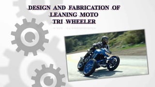
Design & fabrication of leaning moto tri-wheeler
- 2. BATCH-1 T. SUDHAKAR (146M1A0360) K. J N BHARGAVI (156M5A0304) B. S V SWAROOP (146M1A0309) T. BRAHMA TEJA (146M1A0361) N. VENKAT YADAV (156M5A0306) MD. A MUDASSIR (146M1A0339) BATCH-2 B.SAI SHANKAR (146M1A0305) SK. AJI REHMAN (156M5A0309) N. HONEY BABU (146M1A0341) A. SAI GANESH (146M1A0303) V. SURYA SAI TEJA (146M1A0367) SK. SHARIFF (146M1A0333) TEAM MEMBERS PROJECT GUIDE: Mr. K RAVITEJA M.Tech., (PhD) Assistant Professor
- 3. INDEX Abstract Introduction History Architecture Materials and Properties Design Fabrication Advantages Reference Conclusion Future Scope
- 4. ABSTRACT In present days most of the accidents are caused by vehicle instability occurred during turnings at high speed. Architecture is based on the model in which the vehicle contains two wheels on the front side and one wheel on the rear side. The Architecture is unique as compared to other vehicles. It is based on tadpole trike. Our motto is to increase the stability and traction forces of the vehicle which provides safety to the rider, while taking turns at high speed. We have made our design by using CATIA V5 software. Keywords : Stability , Tadpole trike , Traction.
- 5. INTRODUCTION According to the World Health Organization, road traffic injuries caused an estimation of 1.25 million deaths worldwide in every year. That is, one person is killed for every 25 seconds. In the single vehicle accidents, motorcycle rider error was present about two-thirds of the accident cases, with the typical error being slide-out and fall due to over braking or running wide on a curve due to excess speed. In order to eradicate these accidents we have adapted tadpole trike in leaning moto tri wheeler.
- 6. HISTORY Can-Am Spyder is a three-wheeled motorcycle manufactured by the Canadian firm, Bombardier Recreational Products (BRP) in 2007. The vehicle has a single rear drive wheel and two wheels in front for steering, The Spyder uses an ATV-like chassis. The Spyder has traction, stability control, antilock brakes and reverse gear. The Spyder also has front and rear brakes which are both actuated by the same foot pedal. Spyder has no tilting action where the frame is fixed with tie rod end. Spyder has no independent suspension system fixed to the wheels. Can am spyder
- 7. The front suspension consists of a tilting parallelogram system with two steering tubes and twin rear shock absorbers. Front suspension design is easier in the delta type when compared to tadpole, it is complicated. In delta trike mostly adaptable are telescopic fork while in tadpole, multiple choices are available for the front suspension. ARCHITECTURE
- 8. In the delta design the vehicle is inherently unstable in braking when the turning takes place, as the combined tipping forces at the center of gravity from turning and braking can rapidly extend beyond the triangle formed by the contact patches of the wheels. If it is not tipped, it has a greater tendency to spin out when handled roughly.
- 9. MATERIALS & THEIR PROPERTIES MATERIALS USED: AL6063 STAINLESS STELL MILD STEEL PROPERTIES: AL6063 has maximum tensile strength more than 130MPa and maximum yield strength. The material has elongation ( stretch before ultimate failure). STAINLESS STEEL covers a variety of corrosion resistant steels that contain a minimum of 11% of chromium. It contains a mechanical properties of higher strength and hardness and low maintenance. MILD STEEL is very strong due to low amount of carbon it contains.it has a high resistance to breakage.it is very strong and can be made from readily available natural materials.
- 10. DESIGN Design of leaning Moto triwheeler We have completed our design in CATIA V5
- 11. COMPONENTS Body Frame is made up of material Al 6063. Al 6063 is a combination of aluminium alloy with magnesium and silicon . BODY FRAME
- 12. The base is made up of the mild steel which is attached to the T-Fork. It plays a key role in the frame. It is attached to the ends of the rod end bearings on the adjacent sides of it. BASE ATTACHED TO T FORK
- 13. Rod end bearings are made up of mild steel. These are also known as Heim Joint. These are classified into two types. Male Threaded Rod End Bearings. Female Threaded Rod End Bearings. It has an advantage that the ball insert permits the rod or bolt to rotate more than 90 degrees. ROD END BEARINGS
- 14. The Heim joints (left and right side) are attached on the opposite side by using Bright bar. It is made up into V-shape where one end is attached to the wheel frame and other end to the base of T-fork. TOP LINKS MADE INTO V FRAME
- 15. It is a device used for absorbing sudden loads and shocks. Suspension system is classified into Leaf springs Coil springs Torsion bars Rubber springs Shock absorber SUSPENTION SYSTEM
- 16. Coil spring has a mono suspension, it is a kind of torsion spring which can store energy and release it later. These are mostly used with independent suspension system. It takes both shear as well as bending stresses SHOCK ABSORBER
- 17. Wheels are made up of alloy material ,which are light in weight. Alloy material is a combination of steel and aluminium or magnesium. Aluminium or magnesium have greater strength ,which have softer, ductility properties and provide better heat conduction. WHEELS
- 18. V-frame is made up of material BENZENE (or) BRIGHT BAR. The v-frame has an inclination of 45 degrees angle. The v-frame is connected to H-Frame and Channel with tie rod ends while bolted with half treaded bolts. V-FRAME FABRICATION
- 19. CHANNEL The channel is made of material MILD STEEL. It is attached to v-frame and the wheel through an axle rod. The channel is also a support to the disk hub for braking. TIE ROD ENDS The tie rod ends plays a major role in the leaning operation. The tie rod ends are used to connect the Channel and the H-Frame. The diameter of tie rod ends are 18 mm and the material is made up of stainless steel.
- 20. H-FRAME The H-frame is made up of material stainless steel and u-clamp is welded to H-Frame to attach with tie rod ends. The H-Frame is a rectangular section which is attached to handle bar to move the vehicle to left and right. T-SECTON The T-Section is the main component used to support the frame section while the wheels are moving on an unequal road. The T-Section base is attached to H-Frame through an u-clamp. At the top the jokers are attached to T-Section.
- 21. The coil springs are attached to top of the T-Section and the base is attached to the V-Frame at an angle of 45 degrees. The coil springs works individually while applying load on the frame Coil springs: Wheels: we have used the alloy wheels I our fabrication due to the hardness of the wheel to withstand the weight of the vehicle.
- 22. Finally the fabrication of our project has completed
- 23. SPECIFICATIONS OF LEANING MOTO TRI WHEELER ENGINE : • Engine Type 4-Stroke, 2 valve Twin Spark Single Cylinder • Displacement (CC) 149 cc • Power (PS@rpm) 14 PS @ 8000 rpm • Torque (Nm@rpm) 13.4 Nm @ 6000 rpm • Bore 63.5 mm • Stroke Length 56.4 mm • No Of Cylinders 1 • Drive Type Chain Drive • Valves (per cylinder) 4 • Fuel System Carburetor • Fuel Type Petrol • Ignition CDI • Maximum Speed 110 Kmph • Cooling System Air Cooled • Clutch Wet, Multi Plate • Drive Type Chain Drive
- 24. BRAKES : • Brakes Front Disc • Brakes Rear Drum CHASIS AND SUSPENSION : • Chassis Type Double Cradle • Suspension-Front 5 Way Adjustable Shock Absorber on both the wheels • Suspension-Rear 5 Way Adjustable ,Nitrox Shock Absorber
- 25. TYRES AND WHEELS : • Tyre size(Front) 90/90-17 • Tyre size(Rear) 120/80-17 • Wheel Size Front : 17” , Rear : 17” • Tyre Type Tubeless • Wheels Type Alloy DIMENSIONS : • Length*Width*Height 2055*1060*755 • Wheelbase (mm) 1345 mm • Ground Clearance (mm) 165 mm • Kerb Weight 144 Kg FUEL : • Fuel Capacity 15 Ltrs • Fuel Reserve 3.2 Ltrs
- 26. The moto tri wheeler has a traction and stability control The moto tri wheeler has two front disc brakes which are actuated by the single lever ADVANTAGES: REFERENCES : BRP MOTORS Can am spyder. Mr.Prasad from Ogley, in Karnataka (Automobile engineer).
- 27. CONCLUSION In present days most of the accidents are caused due to vehicle instability during turnings at high speed and according to world health organization on person is killed per every 25 seconds to eradicate this problem we introduced leaning moto tri wheeler. Thus we effectively fabricated that the vehicle is stable while taking turns and we faced some problems like v-frame elongation and the weight of the vehicle is more and we finally overcame those defects.
- 28. FUTURE SCOPE The length of the v-shape rod should not be more than 10 inches because it takes more radius of curvature while taking turns. By applying pneumatic or hydraulic steering equipment to the center frame makes more easier to turn and tilt which resembles like power steering vehicle.
- 29. THANK YOU